
Abstract
Alternatives to traditional fossil fuel sources of energy are highly sought after. One alternative is wind energy, even though wind turbine output can be difficult to predict because of variability in wind gusts. Optimal wind turbine design parameters have not been definitively established. In this work the effect of blade number and blade mass on efficiency of a wind turbine was investigated.
A simple horizontal-axis turbine was fashioned using a VCR tape motor to which 15-cm spoon-shaped blades were mounted via a semi-rigid rotor hub. Design variables included the number of blades (3 or 6) and mass of blades (no added weight or 5 g added). Using a constant wind source, the rotation rate of the blades (rpm) and the voltage output (V) of the motor for each of four designs were measured.
3 un-weighted blades yielded both higher rotation rate and voltage output than 6 un-weighted blades (P<.001). Adding mass to the blades (5 g to each) also increased the rotation rate and voltage (P<.001). The highest rotation rate and voltage were observed with the weighted, 3-blade configuration (rpmmean=370; Vmean=0.090), whereas the lowest rate and voltage were observed with the un-weighted, 6-blade configuration (rpmmean=324 ; Vmean=0.035). As a secondary means of validating the model, a regression analysis of the motor’s voltage output and blade rotation rate across all trials was performed, revealing a high degree of correlation (R2=0.9999).
Using a custom-made horizontal turbine and under the specific wind conditions of this study, it was found that 3 blades were more effective than 6 blades, and that weighting the blades with 5 g also improved turbine efficiency. These results may be useful in wind turbine design.
As a result of the ongoing energy crisis, scientists are searching for sustainable sources of energy. Although energy can be obtained from wind, solar, and hydroelectric sources, none of these fossil-fuel alternatives is completely dependable. With each of these technologies, there is still significant opportunity to improve performance and dependability.
Wind is an important renewable resource. No matter how much wind is used by turbines to make energy, there will always be more. This is in contrast to natural resources such as fossil fuels. Wind energy is also environmentally friendly, because it does not increase carbon dioxide in the atmosphere like burning oil or coal. However, there are significant limitations to wind energy. The obvious one is that no energy can be produced when wind is absent. Thus, wind cannot be used as a source of base load power except in limited regions where wind conditions are highly predictable. In addition, wind turbines pose a threat to migrating birds. Despite these drawbacks, the electricity generated from wind power has risen in the past decade from 6 billion kilowatt-hours in 2000 to 120 billion kilowatt-hours in 2011. However, there is still room for growth in wind energy, because the amount of electricity produced using turbines in the United States in 2011 was only 3% of the electricity generated that year1.
A wind turbine works on the principles of lift and drag (Figure 1). The lift that turns the blades of a turbine is the same as the lift that keeps an airplane in the air. It is generated by the shape of the blade, which causes the air to flow faster on one side than the other. Under Bernoulli’s principle, air pressure falls as its velocity rises. Therefore, the faster-moving air on the curved side of the blade has a lower pressure than the air on the other side. This causes a net force perpendicular to the direction the wind is coming from. Drag is the resistance against the blades, created by the air as the blade moves through it2.
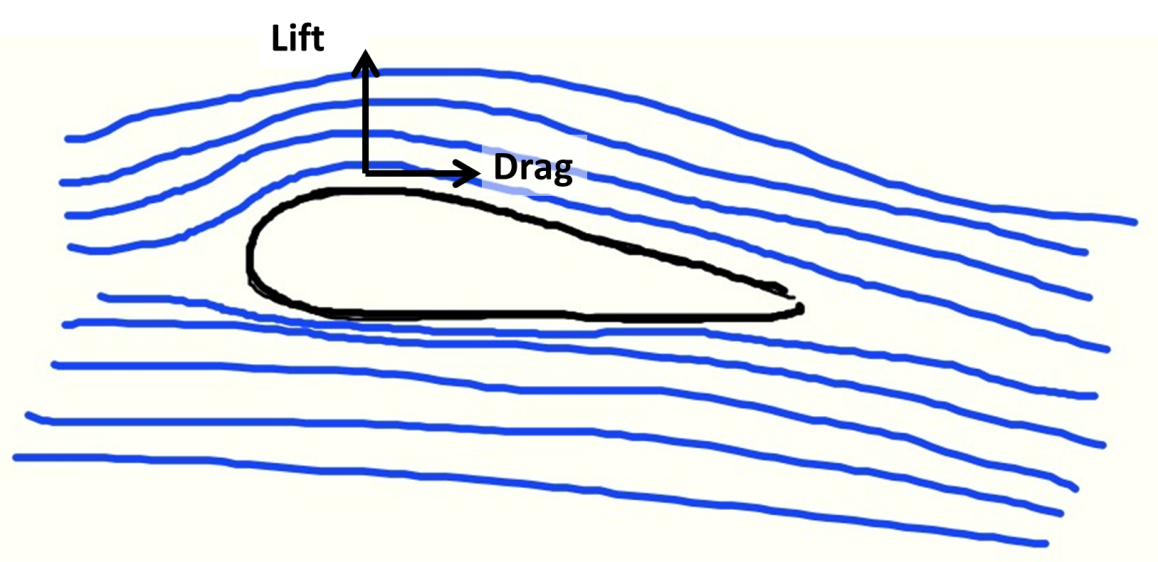
Figure 1: Basics of Lift and Drag
Turbines are very complex machines and there are many factors to consider when optimizing the energy generated. Previous studies have looked at some of these factors, which include blade inclination3, blade size4, blade material5, and load6, many others. This study was designed to examine two specific design parameters, namely blade number and blade weight, on turbine efficiency.
Intuitively, one might assume that increasing the blade number would allow better extraction of wind energy. Previous work has indeed shown that increasing the number of blades from one to three increases efficiency of extraction, but with diminishing returns. Specifically, going from one to two blades led to a 6% increase in efficiency, whereas going from two to three blades led to a further efficiency increase of only 3%7. Furthermore, there is a limit, known as the Betz limit8, which represents a theoretical ceiling on the fraction of wind energy that can be captured. Betz determined that the maximum power, P, obtainable by a wind turbine is related to the power of the wind itself, Pwind, as follows:
P = Cp · Pwind
where Cp is the “power coefficient”. Betz found that the maximum value of Cp is 16/27, or 0.593. Beyond this limit, the vortex created behind the blades leads to slowing of the wind that strikes the turbine2. Modern turbines are almost always made with 3 blades. As pointed out in Scientific American, “[a] combination of structural and economic considerations drives the use of three slender blades on most wind turbines—using one or two blades means more complex structural dynamics, and more blades means greater expense for the blades and the blade attachments to the turbine”9.
The current work examines the possibility that 6 blades might be superior to the ‘standard’ 3-blade model. This study also investigated the possibility that weighting the ends of the blades might affect the efficiency. The hypothesis was that the weighted blades would have more torque and therefore be more efficient.
This investigation consisted of building and testing a horizontal wind turbine to determine the effect of blade number and blade weight.
Experimental Methods
I. Turbine Design
First, a tape motor from an old video cassette recorder (Sony Corporation) was removed and 4 yellow wall anchors were placed into holes on the rotating drum (Figure 2A). Then a frame for the motor was built using two wooden boards, 3 shelf supports and 6 screws. A plastic lid served as a base for the blades, and six 60o pie sectors were drawn with a black marker on the lid. Holes were drilled into the plastic lid and the lid was attached to the wall anchors using screws (Figure 2B). Wooden blocks were placed under the tape motor to level the motor. The wooden blocks were screwed to a large plywood board, and the tape motor was mounted onto the blocks (Figure 2C). Spoons were used for blades and were mounted onto the plastic lid, centered in the pie sectors. One blade was colored in blue, so that turbine rotations could be more easily tracked. For weighted blades, two pennies (weight: 5 grams) were hot glued to each spoon (Figure 2D). The hot glue weight was no more than 1% of the weight of the penny. The turbine was then placed on a chair in an indoor, non-ventilated room, creating a wind free zone. For wind production, a hose was attached to the back end of a portable vacuum cleaner so that air would blow outward. The hose was set up so that the wind would blow at the blades from a direction perpendicular to the blade rotation axis. The hose was secured to a hole in a large wooden frame so that it would provide a steady source of wind for the turbine. A volt meter was attached to the VCR motor’s output wires to measure the current generated by the rotating turbine.

Figure 2. Wind Turbine Design: A. Photograph of tape motor removed from an old Sony VCR, showing 4 yellow wall anchors placed into holes in the motor (red arrows point to the two anchors used to mount the plastic lid). B. Plastic lid with six 60o pie sectors; holes were drilled at sites marked with black circles, to line up with two of the yellow wall anchors on tape motor. C. Mounting of the tape motor onto the leveling blocks. D. Final design of wind turbine showing 3 weighted blades (two pennies each). E. Photograph of hose constrained to blow air perpendicularly at turbine, which was located 2 feet from nozzle (shown with black arrow).
II. Turbine Trials
Either 3 or 6 blades or either non-weighed or weighted blades were used. Therefore, there were 4 different turbine designs. For each design, after turning on the vacuum cleaner and producing wind, measurements were taken after a steady speed was reached. Each turbine design was tested 5 times. Since the rotation rate was not able to be measured by visual inspection, the turbine rotation was videotaped for 30 seconds. Then by slowing down the recording, the rotation rate was accurately measured using the time code of the video recording. For each trial, the voltage displayed on the volt meter was recorded. The voltage was recorded as a range, because the values fluctuated slightly as the turbine spun. The median value of the range was used to calculate the mean voltage of 5 trials for each design.
III. Statistical Analysis
The mean rotation rate and voltage output for each design were compared against the same parameters for each design using Student’s t-test (Microsoft Excel).
Results
The raw data and means are shown in Figure 3, while Figure 4 shows the data in a graphical format. In the base model with 3 un-weighted blades a mean voltage of 0.045V and a mean rotation rate of 324 rpm were observed. These values dropped considerably with 6 un-weighted blades, showing that the addition of blades harms the turbine’s efficiency, and this harmful effect is not overcome by the addition of weights.
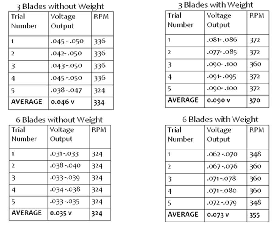
Figure 3. Voltage output and rpm for each of 4 turbine designs.
The model with 3 weighted blades exhibited increased mean voltage and rotation rate in comparison with the un-weighted 3-blade model, indicating that the addition of weight to the blades improves output. When weight was added to the 6-blade model, there was a greater increase in output than was observed when reducing from 6 to 3 un-weighted blades, indicating that additional mass can overcome the impediment of having 6 blades. The largest output was observed with the 3-blade weighted design.
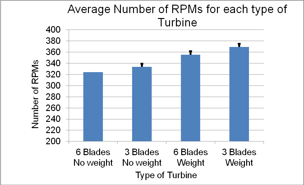
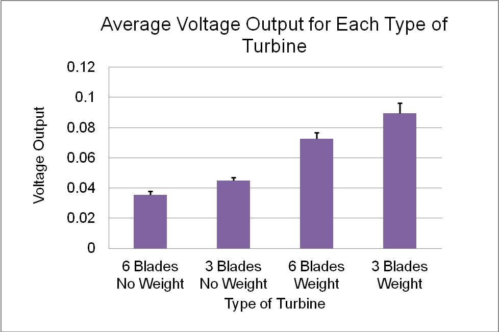
Figure 4. Graphical depiction of RPM (top) and voltage output (bottom) for each of 4 turbine designs. Error bars show standard deviation for each parameter.
All of the observed intergroup differences were statistically significant (P<0.001). The error bars at the top of the graphs (Figure 4) show that the standard deviation of the results was very low and that the results of the investigation were very consistent from trial to trial.
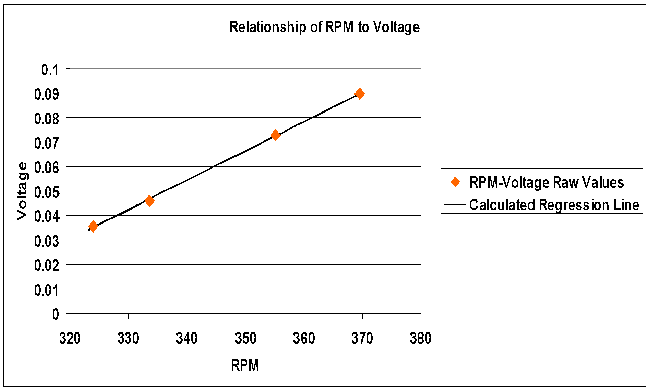
Figure 5. Relationship of RPM to voltage output (red symbols); best linear fit (black line).
The voltage output values were plotted vs. RPM and the best linear fit was determined (Figure 5). The RPM values and voltages lay very close to the regression line (R2=0.9999).
Discussion
This work showed that reducing the blade number from 6 to 3 and adding weight to the blades each independently improved the turbine’s efficiency. The fact that 3 un-weighted blades were more efficient than 6 weighted blades could have resulted from impeded air flow with more blades. It seems unlikely, however, that further reduction in blade number would continue to help the turbine’s output. For example, it would be hard to believe that a single-blade turbine would be superior to a 3-blade turbine. Thus, it is likely that there is a non-linear relationship between blade number and turbine efficiency. There is perhaps an ideal number of blades that is closer to 3 than to 6 when the blades are un-weighted. Further study will be necessary to definitively determine the optimal blade number.
The finding that 3 blades was superior to 6 blades is consistent with other work that has examined 3, 6, and 12 blades10. In this study, the blades were arranged as symmetrically as possible. Small deviations from perfect symmetry were unavoidable given the crude construction techniques, but such deviations are unlikely to have affected the study outcome, given the fact that the turbine operated smoothly under the experimental conditions of this project.
The finding that increasing the weight of the end of blades improved the turbine’s efficiency was consistent with the prediction, which was in turn based on the notion that heavier blades would exhibit greater torque. This result is consistent with Newton’s laws of motion, in that:
Torque = m·r2 · ![]()
where m=blade mass; r=blade length; and ![]() =angular acceleration
=angular acceleration
Thus, the torque will increase if the mass increases, provided that the acceleration is constant. However, there may be an upper boundary beyond which the increasing weight of the blades will not be helpful, because very heavy blades are unlikely to turn at all. Once again, further study will be needed to establish the optimal blade weight.
The finding that weighting the end of the blade improved output has not been previously reported, and further investigation of this design parameter appears warranted. Even if the finding is validated by future work, it is not certain that weighted blades will be sound from the standpoint of engineering or cost-effectiveness.
This simple model appears to be a good representation of a real turbine because there was a strong, linear relationship between voltage and rotation rate. Moreover, the results of each trial exhibited good internal consistency.
Conclusion
After completing this investigation the following conclusions can be drawn. The hypothesis, which was that increasing blade number and blade weight would improve turbine output, was partially supported by the study. It proved true that adding weight to the end of the blades improved output. However, the turbine had a larger output when it had a lower blade number, disproving the first part of the hypothesis.
Acknowledgments
I would like to acknowledge Mrs. Mechling, my PJAS sponsor in 8th grade for helping me get to the PJAS competition; my father, Dr. Muluk, for helping me to drill the holes and video tape my trials; Dr. Theresa Richards for giving me the opportunity to write up my work; and Professor Tristram-Nagle at Carnegie Mellon University for proofing my paper and for helping me to publish my work.
featured image source: http://www.everblue.edu/blog/east-coast-wind-energy
- “EIA Energy Kids – Wind.” [Online]. Available: http://www.eia.gov/kids/energy.cfm?page=wind_home-basics. [Accessed: 23-Aug-2012]. [↩]
- “Wind Energy Composite Materials Handbook from Gurit.” [Online]. Available: http://www.gurit.com/wind-energy-handbook.aspx. [Accessed: 23-Aug-2012]. [↩] [↩]
- M. R. Castelli and E. Benini, “Effect of Blade Inclination Angle on a Darrieus Wind Turbine,” J. Turbomach., vol. 134, no. 3, p. 031016, 2012. [↩]
- D. a. Griffin and M. D. Zuteck, “Scaling of Composite Wind Turbine Blades for Rotors of 80 to 120 Meter Diameter,” J. Sol. Energy Eng., vol. 123, no. 4, pp. 310–318, 2001. [↩]
- P. Brøndsted, H. Lilholt, and A. Lystrup, “Composite materials for wind power turbine blades,” Annu. Rev. Mater. Res., vol. 35, no. 505, p. 538, 2005. [↩]
- P. Volund, “Loads on a horizontal axis wind turbine operating in wake,” vol. 39, pp. 317–328, 1992. [↩]
- E. Hau, Wind Turbines Fundamentals, Technologies, Applications, Economics, 2nd ed. New York: Springer, 2006, p. 121. [↩]
- A. Betz, Introduction to the Theory of Flow Machines. Oxford: Pergamon Press, 1966. [↩]
- D. E. Berg, “Why do wind turbines have three narrow blades, but ceiling fans have five wide blades?,” Scientific American, Feb-2009. [↩]
- “Wind Energy And Wind Power: Effect of blade number on aerodynamic performance in wind turbine.” [Online]. Available: http://winds-energy.blogspot.com/2009/04/effect-of-blade-number-on-aerodynamic.html. [Accessed: 23-Aug-2012]. [↩]


 Sensor Array for Breath-Based Diabetes Screening")