
Abstract
The Federal Aviation Administration’s (FAA) Safety Management System (SMS) and modern Air Traffic Control (ATC) system have revolutionized aviation safety through advanced surveillance, communication, and procedural standards. Despite these advancements, tragic incidents like the January 29, 2025, collision between an American Airlines flight and a US Army Helicopter reveal ongoing challenges in airspace safety. Air traffic is increasing rapidly with the widespread adoption of Unmanned Aerial Vehicles in commercial, military, and recreational sectors. The Traffic Collision Avoidance System (TCAS) provides critical protection for commercial aircraft. The integration of UAVs and drones into shared airspace demands innovative, scalable solutions to prevent collisions and operational failures. This paper presents a practical, low-cost solution to enhance UAV safety, addressing critical gaps in collision avoidance for the evolving shared airspace landscape. With a limited number of experiments performed, and UAVs in close proximity, the accuracy is close to 100%, but it requires extensive experiments across wider UAV models and various environmental conditions.
Keywords: UAV, Drones, Mid-air Collision, Radio Communication, GPS, Raspberry Pi.
Introduction
On January 29, 2025, American Airlines Flight 5342 collided in midair with an Army Black Hawk helicopter near Washington’s Ronald Reagan National Airport, all 64 people on board were killed. It was the deadliest US air disaster since 20011.
A high-level cause analysis revealed multiple reasons for the collision. The ATC instructed the AA flight to change its regular runway from 1 to 332. The helicopter pilot requested and ATC agreed to maintain visual separation from the AA flight, however, the helicopter crew was wearing night vision goggles, and due to the low visibility they could not maintain the separation3. The helicopter pilot and instructor reported conflicting altitudes, 300 ft versus 400 ft respectively, indicating a potential discrepancy between the barometric and radar altimeters, suggesting that each pilot may have been referencing a different instrument1. Finally, the ATC radioed the helicopter to pass behind the AA flight but due to interference and cross-communication the helicopter crew could not get the complete instruction4. Overall, the root cause appears to involve a combination of sensor malfunction, pilot error, and miscommunication between ATC and the pilots.
Flight data analysis from 2011 through 2024 near Reagan National Airport found that at least one TCAS RA was triggered per month due to proximity to a helicopter3. From 2021 to 2024, there were 15,214 occurrences between commercial airplanes and helicopters, with a lateral separation of less than 1 nautical mile and vertical separation of less than 400 ft. Moveover, there were 85 events with a lateral separation less than 1,500 ft and vertical separation less than 200 ft3. This highlights a critical gap in low-altitude collision avoidance systems.
Unmanned aerial vehicles or drones are quickly becoming popular across many industries. In the commercial sector, drones are used for retail delivery, agriculture, mapping, surveying, and filming. They also play a key role in public safety, including disaster management, search and rescue, and firefighting. Thanks to technological advancements and lower costs, drones are being adopted at a much faster rate than expected. This rapid growth is leading to increased air traffic congestion and safety concerns, especially at lower altitudes.
This research paper investigates how aircraft collision avoidance technologies work. And how the collision avoidance system can be adapted for UAVs and drones. The research objective is to find a low-cost, collision avoidance system which is easy to build with off-the-shelf components such as Raspberry Pi, GPS modules, and RF transceivers. The paper will outline the system’s design, methodology, and limitations, while exploring opportunities for improvement in real-world implementation.
Comparative study
ATCRBS
The airline industry has used the Air Traffic Control Radar Beacon System (ATCRBS) for many years. This system helps ATC track every plane’s exact location on radar, so they can guide flights and keep safe distances between them. It operates on three main components:
- Interrogator: Radar works by sending out radio waves. When these waves hit an airplane, they bounce back. The radar then picks the bounced-back signal and shows the airplane as a dot on the controller’s screen (radarscope)5.
- Transponder: This is a transmitter-receiver on the flight that automatically gets signals from the radar and sends back info like Squawk Code, altitude status etc5.
- Radarscope: The radarscope displays signals from both the Interrogator and the Transponder, helping the ATC visualize location of each airborne system5.
TCAS
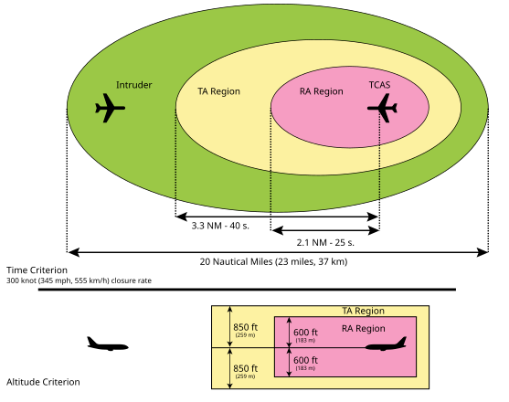
Traffic Collision Avoidance System, early ideas and research started in the 1950s. TCAS II was first installed in 1986 and was made mandatory by the end of 19916. The transponder sends interrogation requests over 1030 MHz RF7. The other aircraft transponder responses over 1090 MHz7. With this sequence of communications, it generates Traffic Advisories or Resolution Advisories. Figure-1 shows the 3D area around an aircraft that is covered by TA/RA.
While TCAS is highly effective, it can generate false alarms at lower altitude due to interference. So, RAs are inhibited below 900 ft for descending and 1100 ft for ascending flights and TAs are inhibited below 400 ft descending and 600 ft ascending8.
ATCRBS and TCAS both use aircraft transponders to share information, but they have different jobs. ATCRBS helps air traffic controllers on the ground track and identify aircraft, while TCAS is on the plane and warns pilots if another aircraft gets too close. Both improve flight safety, but ATCRBS supports control from the ground, and TCAS helps pilots avoid collisions in the air.
ADS-B
Automatic Dependent Surveillance-Broadcast is a modern surveillance technology that enhances air traffic safety by eliminating the need for radar signals or interrogation requests. Instead, it uses GPS and onboard avionics to broadcast precise location, altitude, speed, and other critical data to ground stations and nearby aircraft. Unlike traditional radar, ADS-B provides real-time, highly accurate tracking information, improving situational awareness for both pilots and ATCs. The system includes two key components. ADS-B Out, which transmits the flight’s location and additional details, and ADS-B In, which receives weather and traffic updates10. While ADS-B typically relies on ground stations to relay data, ADS-R (Rebroadcast), newer applications allow direct communication between nearby aircraft10.
UAVs with Collision Avoidance System
As of 11/2025, drone manufacturers offer a wide range of models with different obstacle avoidance capabilities. High-end drones use advanced sensors like LiDAR, night vision, and radar for 360-degree environmental sensing and 3D mapping11. However mid-range and budget drones ($500) and also high-end drones ($1500) have limited or no obstacle-avoidance features, oftentimes include only basic cameras or infrared sensors for stabilization.
| Drones | Price | Obstacle Avoidance Technology |
| DJI Mini 5 Pro | $739 | 360o Obstacle avoidance + Lidar |
| DJI Mini 2 | $263 | None, only videography |
| Autel Evo Nano | $679 | Single forward-facing obstacle detection |
| Autel Evo II Pro V3 | $2,999 | 12 visual sensors and ultrasound |
| Parrot ANAFI Thermal Drone | $1,749 | Thermal Imaging Only |
| Holy Stone 360 S | $199 | None, only videography |
Proposed Solution
Current research on UAV collision avoidance systems can be categorized in 4 groups, obstacle detection, collision avoidance, drone swarm, and path optimization14. Collision avoidances are further classified as static (buildings and trees) and dynamic (flights, UAVs, birds). The focus of this paper is on collision avoidance between multiple UAVs.
The January 29 crash highlighted ATC communication can fail due to human error. TCAS is ineffective at low altitudes. While LiDAR is valuable for terrain mapping, achieving a full 360-degree 3D scan requires multiple sensors, making it cost-prohibitive for most UAVs. Similarly, relying on vision cameras for object detection requires multiple cameras, extensive image processing and computational power, increasing both cost and complexity. These limitations underscore the need for more practical, affordable collision avoidance solutions for UAVs.
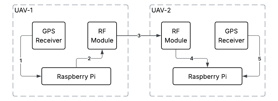
The proposed solution draws inspiration from ADS-B, where UAVs broadcast their location information. Nearby UAVs receive this information like ADS-B In. Using a Raspberry Pi single-board computer, GPS modules, and short-range radio transceivers, the system lets UAVs detect each other and calculate collision risks based on trajectory path calculations. If another UAV gets too close, the system automatically decides to change altitude to avoid collision.
System Design
Communication Protocol
The radio frequency spectrum is divided and allocated for specific uses to prevent interference. Majority of the frequency bands are restricted for the US government, military, aviation, and commercial operators15. The frequency bands available for amateur research are 50-54MHz, 420-450MHz, 902- 928MHz, etc.
Hardware components
- Raspberry Pi Zero 2W: lightweight single-board computers for onboard processing.
- Raspberry Pi Pico 2: single-board computer.
- Adafruit RFM69HCW Transceiver Radio Breakout (915): low-power RF modules enabling direct drone-to-drone data exchange operates in 915 MHz.
- Adafruit Ultimate GPS Breakout – 99 channels – w/10 Hz updates: provides less than 3 meters accuracy with multipath detection and compensation.
- CoDrone EDU: programmable UAV.
Raspberry Pi Zero 2W was used to experiment with GPS and radio signal broadcast. Raspberry Pi Pico 2 was programmed and mounted on UAVs, because of its lighter weight. Both boards use the same GPIO pin layout and do not require any additional configuration.
Adafruit RFM69HCW operates on 915 MHz and 433 MHz16. 915 MHz was chosen for its longer ranges, while 433 MHz provides better obstacle penetration.
Raspberry Pi to GPS Connection
RPI uses the Universal Asynchronous Receiver-Transmitter protocol (UART). The GPS is dedicated to the RPI single-board computer, so it can use asynchronous communication.

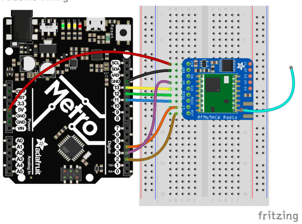
Raspberry Pi to RFM69HCW connection
Serial Peripheral Interface (SPI) is used for high-speed communication between RPI and RFM69HCW. One of the key motivations for using this protocol was that the UART was occupied by the GPS module
| RPI Pins | 2 | 6 | 23 | 21 | 19 | 24 | 22 | 15 |
| RFM69HCW | VIN | GND | SCK | MISO | MOSI | CS | RST | G0 |
Methodology
GPS Data
The GPS module provides the following information for each UAV.
- Timestamp (Month, Day, Year, Hour, Minute, Second)
- Latitude in decimal degrees
- Longitude in decimal degrees
- Precise latitude (degrees and minutes format)
- Precise longitude (degrees and minutes format)
- Number of satellites in view
- Altitude above mean sea level (in meters)
- Speed over ground (in knots)
- Speed over ground (in kilometers per hour)
- Track angle relative to true north (in degrees)
- Horizontal dilution of precision
- Altitude above WGS84 ellipsoid (in meters)
Each UAV broadcasts its location information using an RF module.
| Altitude | Latitude | Longitude | Speed | Angle | Climb Rate | |
| Bytes | 6(3 decimals) | 9(6 decimals) | 10(6 decimals) | 4(1 decimal) | 4(1 decimal) | 5(2 decimals) |
| Example values | 120.936 | -87.967307 | -122.081283 | 120.0 | 270.0 | -13.05 |
Collision Calculation
- Great-Circle Distance (Haversine Formula)19.
The Earth is modeled as a sphere with radius R ≈ 6,378 km. Two points (lat1, lon1) and (lat2, lon2) are positions of 2 UAVs. This computes the surface distance along the earth’s curvature rather than a flat map
(1) 
where
Φ = latitude (Φ1 = latitude_1, Φ2 = latitude_2)
λ = latitude (λ1 = longtitude_1, λ2 = longitude_2)
r = radius of earth
d = distance
- Projecting Future Position (Destination Point Formula)19.
Distance travelled:  , where v is speed and t is elapsed time. New coordinates are calculated using spherical trigonometry:
(2) 
(3) 
where
 = track angle
Distance traveled  : , where
  is speed and
  is elapsed time.
Predicts drone position at each time step, accounting for the Earth’s curvature.
- Incorporating Altitude (3D Distance)
- Altitude is adjusted linearly:

- 3D distance between drones:
(4)

- Altitude is adjusted linearly:
- Collision Detection Threshold
- If D3d ≤ Dsafe ( 15 m + 3 m = 18 m), a potential collision is flagged.
Experiments
Run experiments with a pair of UAVs, each with externally attached RPI, GPS, and RF module. Experiments were grouped into two categories. Multiple UAV interactions or interference from other radio sources is not tested at this level of prototyping due to lack of resources.
- Test RF communication between two UAVs at different distances.
- Test collision detection between two UAVs
Assumptions
- To validate RF communication, one or both UAVs may be at rest.
- The total weight of the RPI, GPS, and RF module is 9 grams. CoDrone can take an additional 10 grams weight. But this might be a limiting factor for other smaller UAVs.
- 5 trials were done for each experiment, the average values are shown in the tables.
Experiment – 1 (Figure-8): Two UAVs at rest (indoor, 1 m distance in between)
| Avg. Latitude | Avg.Longitude | Avg.Altitude (m) | Avg. Speed(m/s) | Avg. Angle(bearing) | Avg. Climb rate(m/s) | Broadcast received | |
| UAV-1 | 35.791947 | -78.781283 | 412.703 | 0 | 0.6 | 0 | yes |
| UAV-2 | 35.791514 | -78.78101 | 412.719 | 0 | 187.6 | 0 | yes |
Experiment – 2 (Figure-9): Two UAVs hovering (indoor, 6 m distance in between)
| Avg. Latitude | Avg.Longitude | Avg.Altitude (m) | Avg. Speed(m/s) | Avg. Angle(bearing) | Avg. Climb rate(m/s) | Broadcast received | |
| UAV-1 | 35.791506 | -78.781100 | 417.811 | 0.3 | 43.7 | 0.06 | yes |
| UAV-2 | 35.791503 | -78.781043 | 417.809 | 0.1 | 224.9 | 0.08 | yes |
Experiment – 3 (Figure-10): Two UAVs hovering at different altitudes (outdoor, 25 m distance in between)
| Avg. Latitude | Avg.Longitude | Avg.Altitude (m) | Avg. Speed(m/s) | Avg. Angle(bearing) | Avg. Climb rate(m/s) | Broadcast received | |
| UAV-1 | 35.791506 | -78.781106 | 417.839 | 0.100 | 63.7 | 0.03 | yes |
| UAV-2 | 35.791521 | -78.781049 | 443.916 | 0.200 | 214.9 | 0.01 | yes |
Experiment – 4 (Figure-11): Two UAVs flying away from each other
| Avg. Latitude | Avg.Longitude | Avg.Altitude (m) | Avg. Speed(m/s) | Avg. Angle(bearing) | Avg. Climb rate (m/s) | Avg. Distance 3D (m) | Collision detected | |
| UAV-1 | 35.791578 | -78.781192 | 417.838 | 1.300 | 33.7 | 0.4 | 25.8 | No |
| UAV-2 | 35.791637 | -78.781467 | 432.916 | 1.100 | 324.9 | 0.3 | 25.8 | No |
Experiment – 5 (Figure-12): Two UAVs flying towards each other (5 m distance in between)
| Avg. Latitude | Avg.Longitude | Avg.Altitude (m) | Avg. Speed(m/s) | Avg. Angle(bearing) | Avg. Climb rate (m/s) | Avg. Distance 3D (m) | Collision detected | |
| UAV-1 | 35.791531 | -78.781192 | 419.832 | 1.400 | 53.1 | 0.4 | 4.5 | No |
| UAV-2 | 35.791657 | -78.781193 | 413.972 | 1.600 | 233.7 | -0.2 | 4.5 | No |
Experiment – 6 (Figure-13): Two UAVs flying towards each other, collision path (10 m distance in between)
| Avg. Latitude | Avg.Longitude | Avg.Altitude (m) | Avg. Speed(m/s) | Avg. Angle(bearing) | Avg. Climb rate (m/s) | Avg. Distance 3D (m) | Collision detected | |
| UAV-1 | 35.734057 | -78.781253 | 398.752 | 1.200 | 15.3 | 0.2 | 10.3 | Yes |
| UAV-2 | 35.732584 | -78.780945 | 396.972 | 0.900 | 195.6 | 0.3 | 10.3 | Yes |
Experiment – 7 (Figure-14): Two UAVs flying towards each other, collision path (15 m distance in between)
| Avg. Latitude | Avg.Longitude | Avg.Altitude (m) | Avg. Speed(m/s) | Avg. Angle(bearing) | Avg. Climb rate (m/s) | Avg. Distance 3D (m) | Collision detected | |
| UAV-1 | 35.734052 | −78.781248 | 398.673 | 1.100 | 16.0 | 0.2 | 15.7 | Yes |
| UAV-2 | 35.732589 | −78.780952 | 397.188 | 1.200 | 196.7 | 0.3 | 15.7 | Yes |
Discussion and Limitations
Experiments 1, 2, and 3 show that two systems within 50 ft can broadcast and receive location information from each other.
Experiments 4 and 5 show that 2 systems can broadcast, calculate distance and collision changes successfully without any data loss.
Experiment 5, though the drones were heading to each other, the distance between them was 4.5 m which is less than safe distance threshold, but because UAV-1 was at higher altitude and was climbing up and UAV-2 was at lower altitude and was climbing down, so no collision was detected.
Power Consumption
RPI Pico 2 is powerful enough to perform
- GPS location updates every second.
- RF broadcasts every second; any UAV statistics loss will have minimal impact.
- Calculate the distance when an RF message is received, in less than a second.
The CoDrone EDU has a flight time of approximately 7–8 minutes and the added components consume an estimated total of 197–247 mA, the additional weight and power draw would reduce the flight time by approximately 1–2 minutes, resulting in an estimated flight time of 5–6 minutes.
GPS Accuracy
The GPS module operates with -165 dBm sensitivity, 10 Hz updates, and 99 search channels to achieve a very highly sensitive receiver with a built-in ceramic patch antenna20. It also supports GLONASS networks for global coverage20. It has a location accuracy variance of less than 3 m. The collision calculation takes care of it with a safe distance calculation of 15m + 3m. If 2 UAVs come within 18 m separation, it would trigger a collision alert.
In the GPS module GNSS quality metrics are possible. The GPS module has metrics such as “# of satellite fixes,” the number of satellites the GPS is connected to to get the location. To get accurate results, any data with fix quality more than 2 is accepted, anything below 2 is discarded. To validate the accuracy of the GPS, Google Maps was used to find the coordinates of the testing grounds, which matched up with the GPS data. The ultimate GPS model already has multipath detection and compensation.
Distance calculation
The Haversine formula assumes that the Earth is spherical, but in reality, it’s an oblate spheroid meaning it bulges at the equator and is slightly flattened at the poles. An alternative to the Haversine formula is the Vincenty/Karney formula, which models the Earth as an ellipsoid for higher accuracy. However, since we are concerned about drone distance less than 200m, the Haversine formula won’t introduce a significant error. Additionally, the Vincenty/Karney formula is much more complex and would require an additional compute cycle.
RF Range
RFM69HCW (915 MHz) module can communicate up to 1500 ft (450 m) with an in-built wire antenna16. Considering the CoDrone’s top speed of 2.5 m/sec (8.2 ft/sec) the RF range is enough for UAV collision detection21.
RF interference
Any other device that operates in 915 MHz (example – LoRa RFM9x) would potentially cause interference. But RFM69HCW has in-built CRC checksum error correction and auto-retransmit, that would minimize the errors16. If this solution becomes a real product, licensing of dedicated ISM bands would be required.
RF Security
The RFM69 can protect the communications using AES (Advanced Encryption Standard) encryption, which is extremely secure. Encryption can be turned on or off by the python module. Both ends use the same 16-byte key. Only those RFM69s using exactly the same key will be able to decode the messages22.
Integration
The single-board computer, GPS and RF module were externally attached to UAV. Further research is needed to fully integrate GPS and RF modules with UAV’s built-in single-board computer; this would eliminate additional single-board computers and additional weight overhead. This would require close collaboration with the UAV manufacturers.
Conclusion
As drone technology advances and autonomous systems become increasingly prevalent, the demand for robust, onboard collision avoidance solutions has never been greater. The experiments show promising results, but this was only an initial feasibility study using Raspberry Pi, GPS, and RF modules. To fully develop this system, more research is needed, testing UAVs across a wider distance, different RF bands, and different UAVs with varying payload. Additional experiments need to be performed when more than 2 UAVs are in proximity.
Appendix
Abbreviations (Figure-15):
| FAA | Federal Aviation Administration |
| SMS | Safety Management System |
| ADS-B | Automatic Dependent Surveillance-Broadcast |
| ADS-R | Automatic Dependent Surveillance-Rebroadcast |
| ATC | Air Traffic Control |
| ATCRBS | Air Traffic Control Radar Beacon System |
| DSN | Deep Space Network |
| GPS | Global Positioning System |
| LiDAR | Light Detection and Ranging |
| RA | Resolution Advisory |
| RF | Radio Frequency |
| RPI | Raspberry Pi |
| SPI | Serial Peripheral Interface |
| TA | Traffic Advisory |
| TCAS | Traffic Collision Avoidance System |
| UART | Universal Asynchronous Receiver-Transmitter |
| UAV | Unmanned Aerial Vehicle |
Source Code:
References
- Funk, J. (2025). A Timeline of Last Month’s Air Disaster in Washington, the Deadliest in the US Since 2001. AP News. [↩] [↩]
- National Transportation Safety Board. (2025). Briefing Points on Mid-Air Collision near DCA. NTSB. [↩]
- National Transportation Safety Board. (n.d.). Aviation Investigation Report AIR2501. NTSB. [↩] [↩] [↩]
- National Transportation Safety Board. (2025). Cockpit Voice Recorder and Air Traffic Control Combined Transcript Factual Report. NTSB. [↩]
- Federal Aviation Administration. (n.d.). Aeronautical Information Manual – AIM – Surveillance Systems. FAA. [↩] [↩] [↩]
- Federal Aviation Administration. (2011). TCAS II V7.1 Intro Booklet. FAA. [↩]
- Harman, W. (n.d.). TCAS: A System for Preventing Midair Collisions. MIT Lincoln Laboratory. [↩] [↩]
- U.S. Department of Transportation. (2025). Advisory Circular AC 20-151. FAA. [↩]
- Wikipedia Contributors. (2019). Traffic Collision Avoidance System. Wikipedia. [↩]
- Federal Aviation Administration. (2022). Automatic Dependent Surveillance–Broadcast (ADS-B). FAA. [↩] [↩]
- DJI. (2022). DJI AGRAS T100. DJI. [↩]
- DJI Support. (n.d.). Introduction to the Aircraft Obstacle Avoidance System. [↩]
- Autel Robotics. (n.d.). Autel EVO II Series. [↩]
- Federal Aviation Administration. (2023). INS and Outs. FAA. [↩]
- U.S. Department of Commerce, National Telecommunications and Information Administration. (2003). U.S. Frequency Allocation Chart. NTIA. [↩]
- Adafruit Industries. (2016). Adafruit RFM69HCW Transceiver Radio Breakout – 868 or 915 MHz. Adafruit. [↩] [↩] [↩]
- TopTechBoy. (2025). Raspberry Pi Pico | Technology Tutorials. TopTechBoy. [↩]
- Adafruit Learning System. (n.d.). Adafruit RFM69HCW and RFM9X LoRa Packet Radio Breakouts. Adafruit. [↩]
- Veness, C. (2019). Calculate Distance and Bearing Between Two Latitude/Longitude Points Using Haversine Formula in JavaScript. Movable Type Scripts. [↩] [↩]
- Adafruit Industries. (2017). Adafruit Ultimate GPS Breakout with GLONASS + GPS – PA1616D. Adafruit. [↩] [↩]
- Robolink. (n.d.). Product Specifications. Robolink. [↩]
- SparkFun. (2025). RFM69HCW Hookup Guide – How It Works. SparkFun. [↩]


