
Abstract
This study explores the development of an autonomous omnidirectional mobile robot (OMR) designed for the RoboCup Junior Lightweight Soccer league. Robots in this competition must process environmental information and make decisions without human intervention. To meet these demands, a standard robot model provided by the RoboCup Korea Association was adopted. The robot is equipped with a compass sensor, infrared receiver, and ultrasonic sensors to recognize orientation and detect the positions of the ball and goal. However, this standard model presented several limitations. First, it lacked strategic scalability and featured no distinctive functions compared to teams from other countries. Second, it relied solely on rule-based algorithms, which limited the reacting speed and flexibility of motion control. To overcome these issues, the robot’s motor specifications were upgraded from 3 kg torque, 730 rpm to 5 kg torque, 980 rpm, and a custom dribbler mechanism was installed to control the ball movements. During these upgrades, inverse kinematics was applied to calculate precise motor speeds for omnidirectional operations. Feedback control system was also implemented using a proportional (P) controller based on data from ultrasonic sensors, a compass sensor, and an infrared receiver. After participating in four International RoboCup Soccer League, the robot demonstrated significantly improved mobility and ball accessibility, enhancing its ability to approach and control the ball while remaining within the field. This work not only improved the robot’s performance but also introduced innovation into the Korean RoboCup Junior league. Many teams began modifying their robots by integrating advanced sensors and developing feedback control systems. The methods proposed in this research may support future advancements in autonomous navigation and robotics education.
Introduction
RoboCup, the world’s oldest and one of the most prestigious AI competitions, has been held annually since 1996. Among its various leagues, RoboCup Junior is specifically designed for young participants, providing an educational platform for students to engage in hands-on robotics challenges. One of its most dynamic and popular events is the Lightweight Soccer League, where two teams of autonomous robots compete to score goals using a special ball that emits infrared (IR) signals. Robots are required to navigate the field and make strategic decisions without any human intervention, relying solely on sensor feedback and control algorithms. A distinctive feature of the robots in this league is their omnidirectional mobility, which allows them to approach the ball from any angle similar to how autonomous vehicles rely on sensor integration and algorithmic decision-making for navigation.
In this study, we utilized a robot based on the specifications provided by the Korean RoboCup Association. The robot employs ultrasonic sensors and a digital compass to estimate both its own position and the locations of the ball and goals. However, a common challenge observed among participating teams is the limited adaptability of the default algorithms and hardware, particularly in scenarios where precise directional control and ball-handling are critical. Many teams encountered difficulties even in basic navigation tasks, such as accurately approaching the ball and aligning with the goal.
To overcome these limitations, the robot was upgraded with high-performance 980 RPM, 5kgf·cm torque motors to improve speed and power. A custom-designed dribbler mechanism was implemented, along with a feedback control system based on a PID controller. Sensor data from ultrasonic and infrared modules were integrated into the control loop, enhancing the robot’s ability to track and control the ball while maintaining stable movement. Additionally, the dribbler mechanism was optimized using geometric principles, including the Pythagorean theorem, to ensure that the ball remained securely attached during motion.
These technical enhancements significantly improved the robot’s maneuverability and precision, allowing for more accurate and dynamic ball handling during matches. As a result, the innovations introduced in this study not only elevated the performance of our robot but also contributed to a shift within the Korean RoboCup Junior community. Inspired by the success of this customized approach, many teams began developing their own modifications such as adding advanced sensors and constructing custom dribbler mechanisms demonstrating the broader impact of this research.
Ultimately, this work bridges foundational scientific and mathematical concepts with practical robotics development. It serves as a valuable case study for educational robotics and may also inform future research in autonomous navigation and intelligent robotic systems.
Theoretical Background
Feedback Control System
The fundamental structure of a feedback control system involves both variable and constant, where sensor and encoder inputs serve as essential external elements. Sensor values define the variables of the system and act as input parameters. Inputs are then adjusted through feedback mechanisms by applying appropriate constants. Among various approaches, the PID controller is the most used feedback control strategy. The standard PID control equation is given by:
(1) 
In this study, a proportional control system derived from the PID controller was implemented to govern the motion of the OMR. The robot utilized four ultrasonic sensors, a gyroscope, and twelve infrared receivers to acquire real-time feedback variables. The system allowed for responsive motion control based on sensor input fluctuations over time.
Inverse Kinematics
Inverse kinematics is the fundamental principle in controlling OMR. Unlike the rule-based control system such as the conditional switch function in C programming, an inverse kinematics approach enables a more efficient and responsive system by minimizing code redundancy and enhancing real-time precision.
The key feature of omnidirectional structure is the interdependent motion of all wheels, even though each motor generates force in a single direction. To capture this relationship, the robot’s motion is expressed in a Cartesian coordinate system.
The basic rotational force equations can be expressed as:
(2) 
(3) 
The OMR is actuated by the interactions among three motors with omni wheels. The translational components  and
and  axes, as well as the angular velocity
  , are derived from the vector sum of the individual motor forces. A compass sensor is employed to stabilize the heading angle of the robot, allowing for accurate linear movement. The wheel orientation angles are defined as
  ,
,  ,
,  .
.
(4) 
The definition of the factors, factors and angular velocity of the robot itself are:
(5) 
(6) 
(7)
The converted form of three equations above into  matrix is:
(8) 
The inverse matrix can be obtained using the following formula.
(9) 
When assuming  indicates matrix,
(10) 
The determinant of matrix is:
(11) 
The cofactor matrix and its transpose are:
(12) 
(13) 
(14) 
Consequently, an inverse matrix  appears as follows.
(15) 
(16) 
Through the calculation above, the exact values of  ,
,  , and
, and  are obtained. The final inverse kinematics equations determining each motor output, based on the desired robot motion are:
(17) 
These expressions allow for precise computation of each wheel’s force requirement, enabling coordinated OMR movement and effective feedback control.
Force interactions on robot motion with the ball
In previous studies on the dribbling system1,2 the ball trajectory modeling was implemented. Fundamentally, a camera-based tracking system is essential for modeling the trajectory of the ball. Building upon previous studies that have focused on ball path planning, this study analyzes the decomposition of force interactions between a rotating ball and the frictional resistance of the playing field.

The interaction between the dribbler system and the ball follows Newton’s third law. The forces exerted by the robot and the ball form an action-reaction pair Fig 1.a (left). This dynamic relationship determines how long the robot can maintain the ball possession while the continual impact from the ball and other robots. To enable omnidirectional movement while spinning the ball, the force applied to the ball must overcome the frictional resistance from the field surface Fig 1.a (right). An RPM of 2352(no load) was experimentally determined to maintain ball control to overcome the friction from the field.

In Fig. 1.b, the overview of force interactions acting on the ball is illustrated. Based on the diagram adapted from previous studies (right), vector decomposition is crucial for understanding the curved motion of the ball. To induce such motion, a dribbling system and a solenoid device were implemented. The ball control strategy employed in this study differs from those in earlier research, primarily due to the relatively small size of the field. Instead of replicating the curved shot trajectories emphasized in previous work, this study focuses on effectively transferring the ball’s spin-induced inertia to enable it to move directly toward the goal, even when the robot is positioned far from it.
Research procedure
Initial Hardware Setup
The performance of the developed robot was evaluated through participation in four RoboCup Junior competitions over the span of two years. Each tournament served as a platform to test and refine the system, applying different hardware configurations and software algorithms tailored to the specific competition environments.
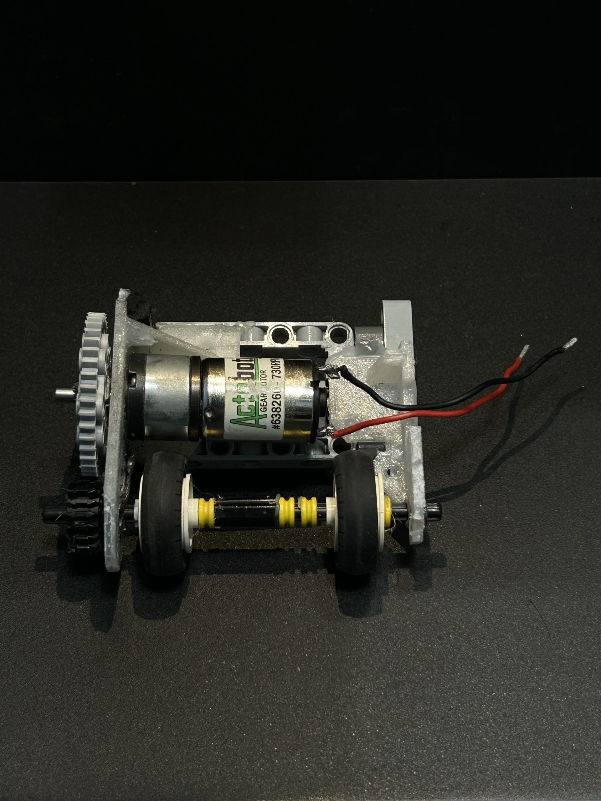
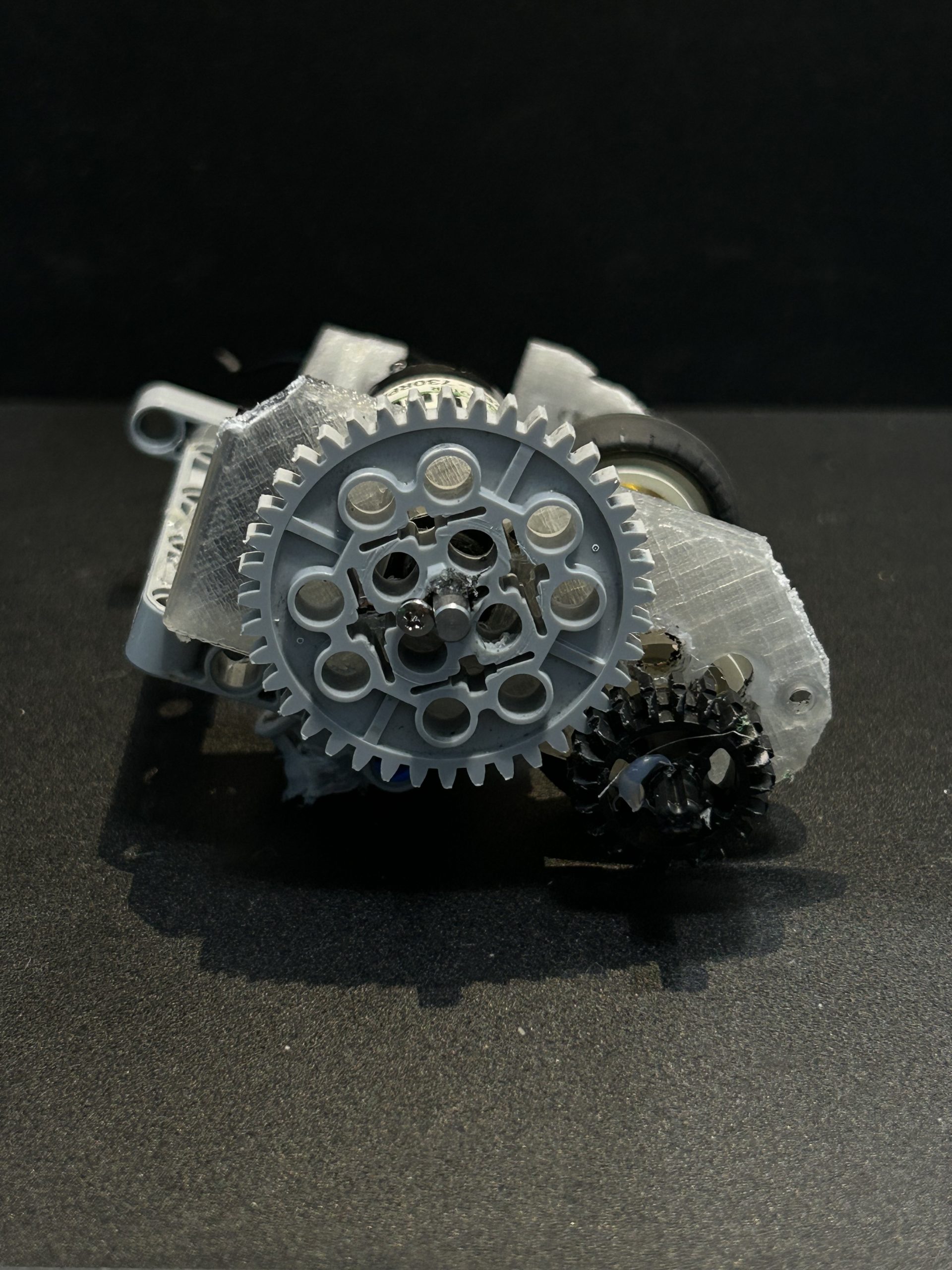
Table 1 outlines the chronological development of the robot, highlighting the engineering progress made in each iteration. Integration of new control strategies, sensor feedback systems, and mechanical enhancements were included. In the first RoboCup Junior competition, a pre-assembled robot kit was purchased from the Korea RoboCup Association and subsequently modified for use. Arduino Mega2560 control board, three motors equipped with omni wheels, and various types of sensors were included. A dribbling device was custom-built and a solenoid was attached to a 3D-printed frame, replacing the original structure. Table 2 outlines the hardware details of the robot used in the first experiments aiming the RoboCup participation.
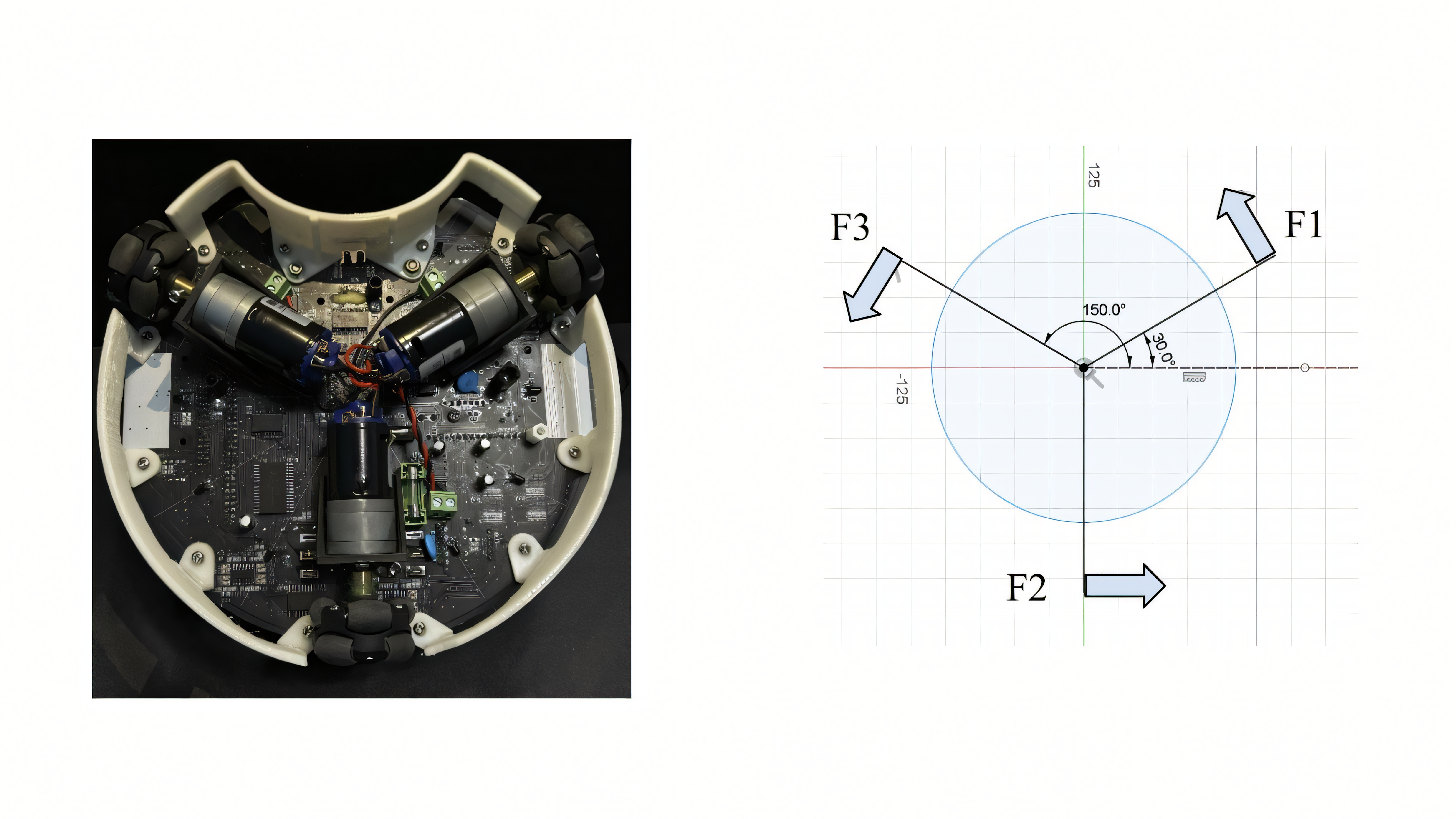
Unlike conventional wheeled robots, the omnidirectional mobile robot consists of three or four omni wheels. Each omni wheel is arranged at a constant angle. Three omni wheels were positioned 120° degrees apart in this research. Due to the environment of the RoboCup Soccer league where robots frequently change positions, OMR Fig. 2.a was adopted to ensure the robot immediately react to its rapidly changing situation. The three omni wheels interact on each other based on the motors positioned in 120 degrees apart supplying the momentum to the robot. In Fig 2.a, the arrows indicate exact heading direction of omni wheels.
Design of the dribbling System
The dribbler system allows the ball to remain adjacent to the robot by using two rubber wheels rotating at high revolutions per minute (RPM). These wheels not only secure ball control but also contribute to stabilizing yawing motions during omnidirectional movement.


Taking inspiration from the dribbling devices developed by Team ROBOFEI (RoboCup SSL League)3 and previous research4, a damper system was incorporated into the dribbling device to reduce impact by prolonging the contact time during ball tracking (18). This integration effectively minimized the force transferred during collisions with the ball.
(18) 
When the dribbling device applies frictional force to the ball,  ,
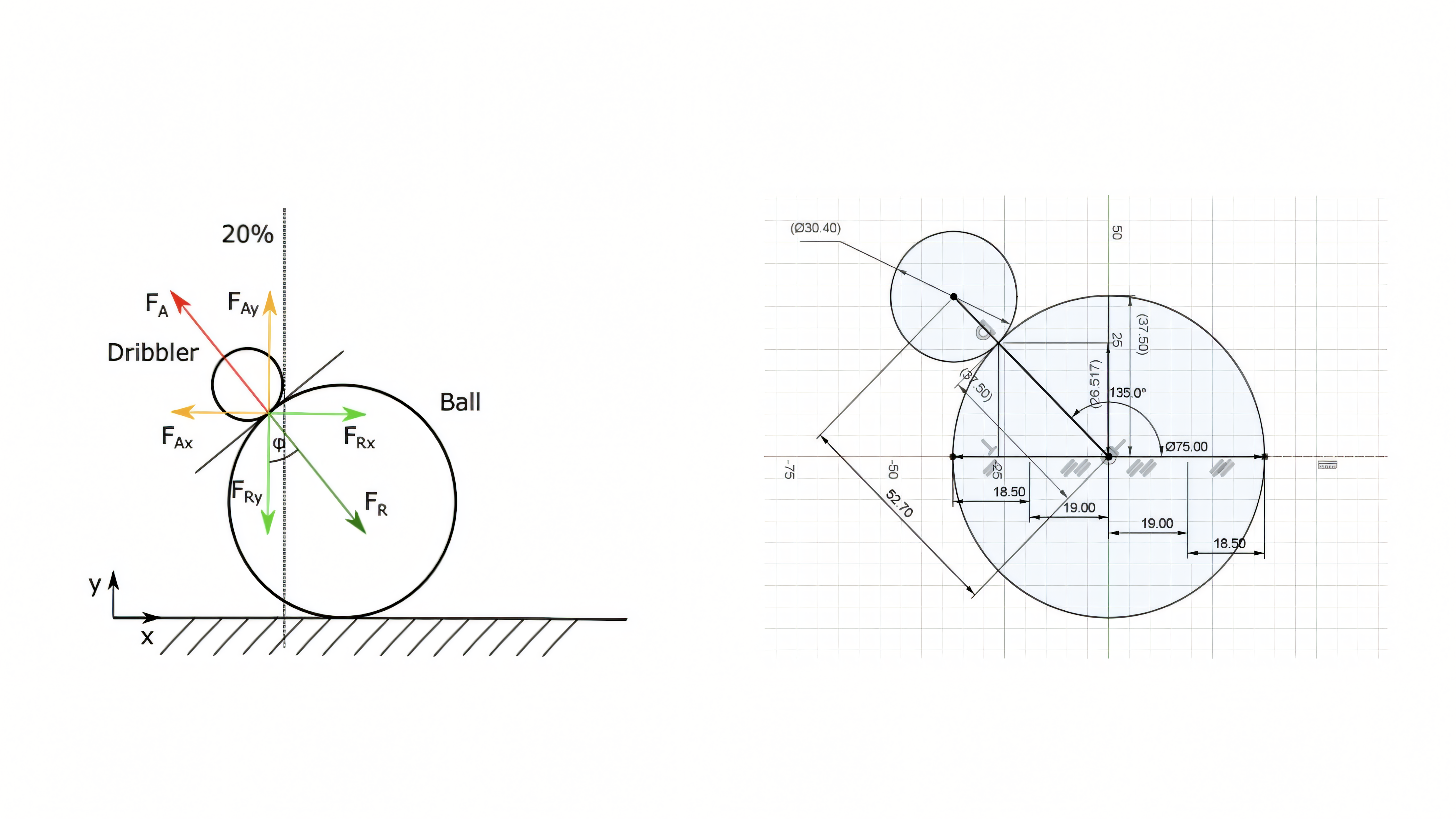
,  two primary forces are generated. describes the reactive force from the ball and describes the applied force from the dribbler. These forces form an action-reaction pair, in accordance with Newton’s third law. Both and act perpendicularly to the point of contact and can be decomposed into their respective vertical and horizontal components (
 ,
,  ,
,  , and
, and  ).
).
(19) 
To comply with the rule prohibiting possession of more than 30% of the ball, a triangle was constructed with the line segment connecting the ground contact point between the ball and the dribbler and the origin of the robot as the hypotenuse. Specifically, the Pythagorean theorem (19) was applied, and the actual distance between the ground contact point and the origin was determined to be 26.517 mm. Considering the ball’s diameter of 70 mm, the dribbler was positioned at 64.017 mm. The ground contact point between the ball and the dribbler reaches its theoretical maximum, enabling the most effective transfer of force.
Ultrasonic Feedback Control – Phase 1
After implementing a dribbling system that marked a technical breakthrough during the first participation in RoboCup, innovation by analyzing and comparing the movement patterns of robots in the RoboCup Major Small Size League (SSL) was pursued. Unlike robots in the RoboCup Junior league, which primarily apply linear motion, SSL robots demonstrate variable speed depending on their position relative to the ball and the goal.
This difference revealed a key limitation: the constant velocity motion in Junior League robots resulted in difficulties when approaching the ball from the periphery of the field toward the goal located in the center of the field. Even if the ball entered the robot’s capture zone, the robot would continue moving in a straight line, causing difficulties in accurately conveying the ball to the goal.
To address this issue, we focused on the observation that the closer the robot is to the goal, the greater the angular adjustment required to orient. In a three-wheeled omnidirectional robot, the two side motors adjacent to the ball capture zone were programmed to maintain forward motion based on the ultrasonic sensor feedback control system. Their speed was gradually reduced as the robot approached the goal, improving shooting accuracy.
In contrast, the third motor which contributes only along the x-axis was utilized for directional feedback. Specifically, feedback from ultrasonic sensor 2, mounted at the rear of the robot was used to regulate the motor’s behavior based on changes in its sensitivity to the rear wall. This allowed the robot to make appropriate directional corrections.
To estimate the robot’s position based on motor rotation and ensure precise motion control, Equations (20) and (21) were employed.
(20) 
(21) 
To determine the maximum forward velocity of the robot, ten speed measurement trials were conducted on a testing platform with floor friction. During linear motion, the robot demonstrated an average velocity of 1.03 m/s. Based on this result, a reference framework was established to estimate the robot’s approximate speed and travel distance under power levels in the PWM control system, where 100% represents the maximum output. The graph below presents the relationship between time, velocity, and position change observed in this experiment.

Based on the graph presented above, the trend of ultrasonic sensor sensitivity during the robot’s forward motion was analyzed. As robots advance toward the goal, the sensitivity of Ultrasonic Sensor 2 gradually increases. This trend indicates that the required rotational angle for the robot to reorient itself toward the goal also increases to accurately direct the ball to the center of the goal.
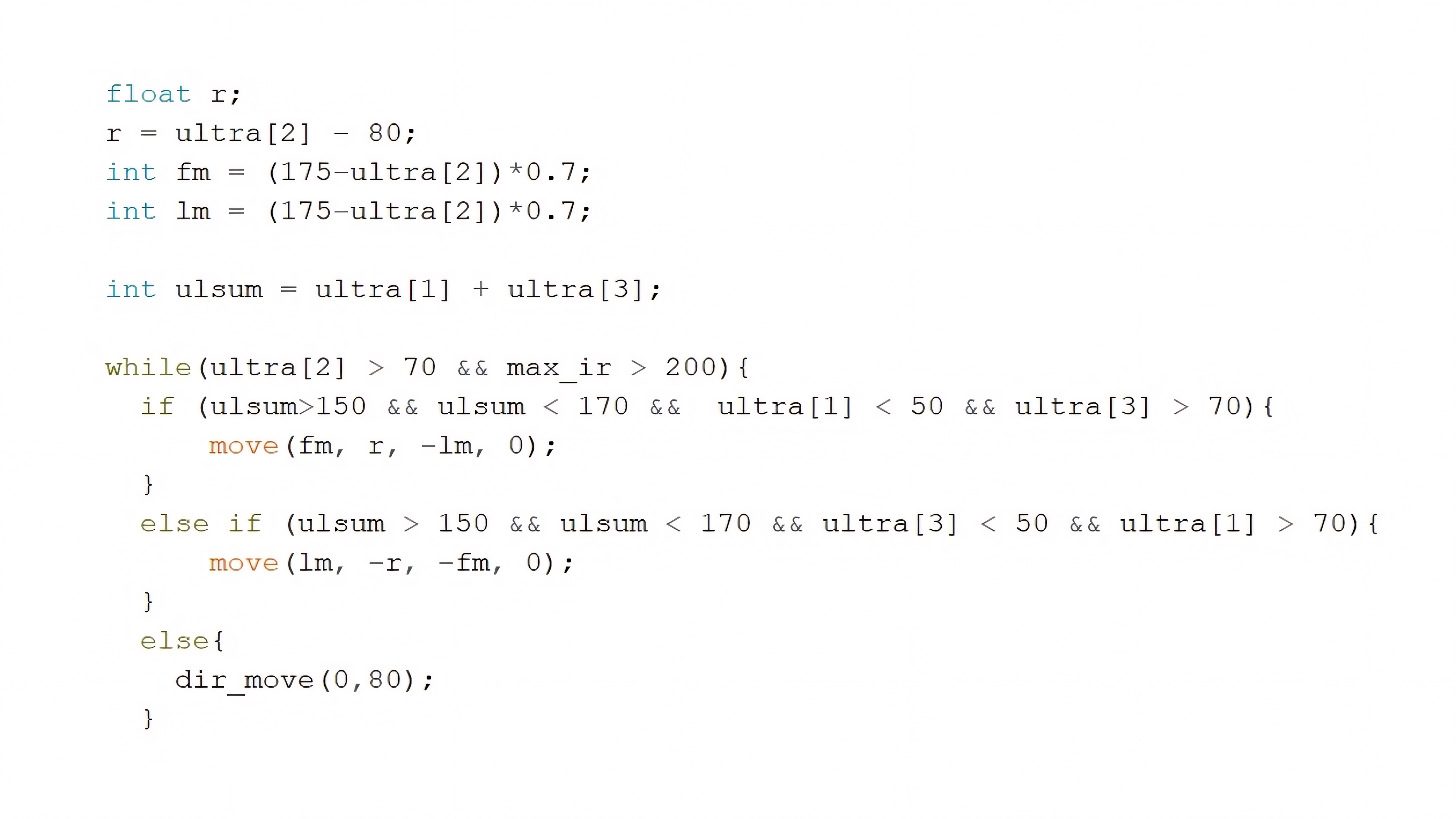
Using these observations, we conducted ten experiments to analyze the variation in the robot’s rotational angle relative to its position. As a result, an equation by subtracting 80 from the sensitivity value of the ultrasonic sensor was developed. This equation is subsequently applied to Motor B, which directly influences the robot’s movement along the x-axis.
Additionally, the variables  and
and  , were defined to serve as part of the ultrasonic sensor-based feedback control system for forward motion. These are designed to reduce the robot’s speed near the goal area, thereby increasing positional precision when delivering the ball into the goal. Fig 4.b presents the C-language implementation of the ultrasonic sensor feedback control system.
Ultrasonic Feedback Control – Phase 2
Based on the Phase 1 ultrasonic sensor feedback control system, the robot was deployed in the 2022 RoboCup Asia-Pacific Championship. However, unlike the experimental conditions, frequent disturbances occurred during actual matches due to physical interactions with opposing robots, often causing the robot to deviate from its intended direction. This revealed a limitation of relying solely on a single ultrasonic sensor for determining the robot’s position and desired movement direction.
To address this issue, a triple-sensor system was implemented, employing two ultrasonic sensors to measure the distance between the robot and the side walls of the field. Although the use of a front-facing ultrasonic sensor was initially considered, it was ultimately excluded due to the difficulty of obtaining accurate measurements in situations involving collisions with opponent robots or the ball.
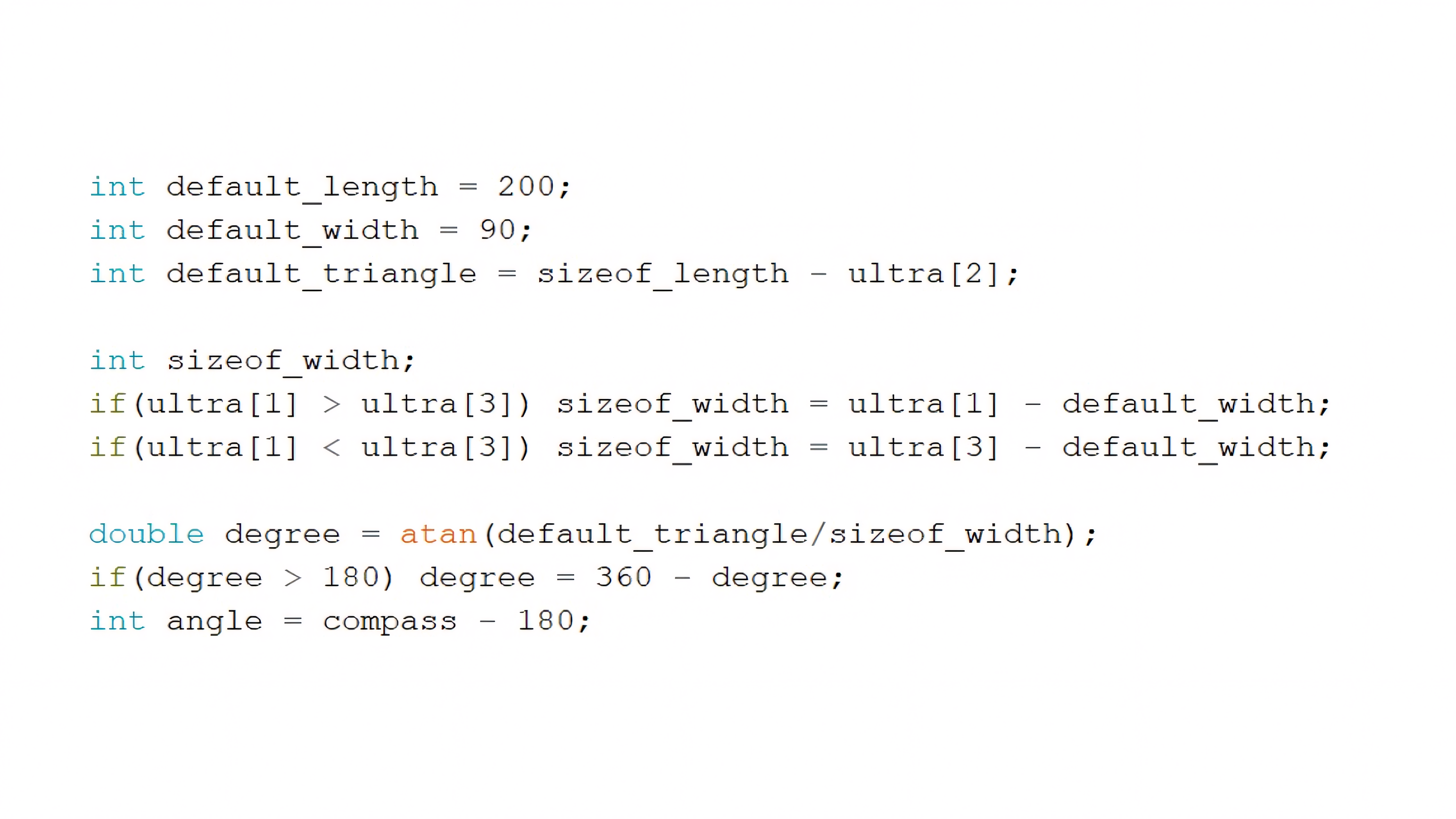
The code in Fig 4.c utilizes three ultrasonic sensors to calculate the angle between the robot’s heading direction and the center of the goal. Assuming a fixed field size, the distances from the robot to the side walls were measured using two side-facing ultrasonic sensors. Additionally, the distance to the rear wall was obtained using Ultrasonic Sensor 2.
By combining these measurements, the robot’s position within the field could be accurately determined. Using inverse trigonometric functions, the angle between the robot’s current heading and the center of the goal was calculated based on changes in position.
This approach effectively compensated for the angular deviations caused by collisions observed in Phase 1. Furthermore, it provided dual feedback not only to the motor control system but also to the gyro sensor, thereby improving the stability and accuracy of the robot’s path planning process.
Application of Inverse Kinematics
In previous studies5,6 the Jacobian matrix was applied to analyze the linear motion of OMR. During the path planning process, the vector components of each motor were decomposed into and directions to determine the desired movement direction of the robot. In other words, it is essential to obtain and components by summing the directional components of each motor to compute the trajectory of the robot itself,
In previous experiments, the rule-based switching control system was adopted to control the OMR. Instead, linear motion was achieved more precisely by leveraging the directional data collected from twelve infrared sensors. A key distinction from previous approaches is that the robot operates omnidirectionally while maintaining a fixed heading direction. As a result, angular velocity was integrated as a third component, and matrices were constructed. By calculating its inverse, the force magnitudes allocated to each motor depending on the user’s setting was precisely calculated.
The final form of the inverse matrix, as introduced in the theoretical background section, is as follows:
(22)
From equation (22), three equations representing the power distribution among the motors are derived:
(23) 
To decide the direction for the linear motions, the numbers of the infrared receivers were converted into circular measures:
(24) 
(25) 
(26) 
Consequently, the accurate power decompositions on each motor can be expressed in C (Fig 5.a).
By applying the matrix formulation above, the instability observed in rule-based omnidirectional control was significantly improved. In previous studies, the direction and force distribution of each wheel were decided only using proportional relationships, due to limitations in accurately calculating motor contributions for a desired movement direction. In contrast, the matrix-based approach enabled precise power allocation to each motor based on the intended trajectory of the robot.
Infrared based feedback control system
The experiment, conducted in preparation for the RoboCup 2023 Asia-Pacific competition, primarily focused on the sensor-based feedback control system. As shown in Table 1, the robot’s motion was controlled using ultrasonic sensors, a gyroscope, and an infrared receiver, depending on their varying outputs. After integrating the ultrasonic sensors and the gyroscope into the feedback control system, the infrared receiver-based feedback mechanism was developed as the final step of the project.
For the infrared-based feedback control system, difficulties were encountered in establishing a proportional relationship between sensor values and the robot’s motion. The variation in infrared sensor output was examined through manual testing. It was observed that the signal intensity significantly decreased when the distance between the ball and the receiver exceeded 200 mm. Consequently, the numerical relationship between the infrared sensor values and the ball-robot distance can be expressed as follows:
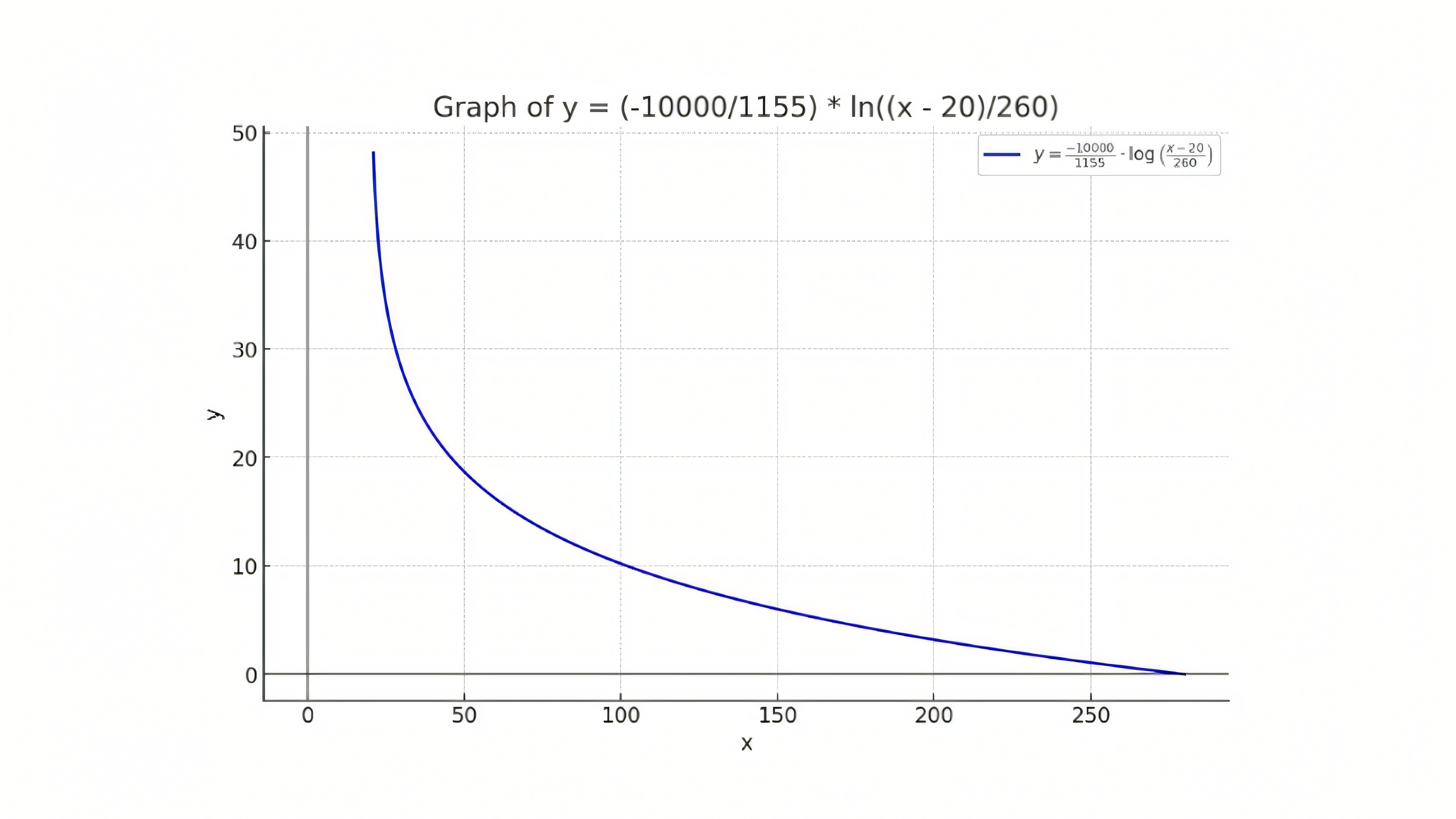
(27) 
GeoGebra was used to obtain Equation (27) based on the experimental data.
Fig 6.a illustrates the nonlinear response of the IR sensor, modeled by a logarithmic function. The function demonstrates that small increases in IR signal () in the lower input range result in rapid decreases in control output (), reflecting high sensitivity to proximity changes.
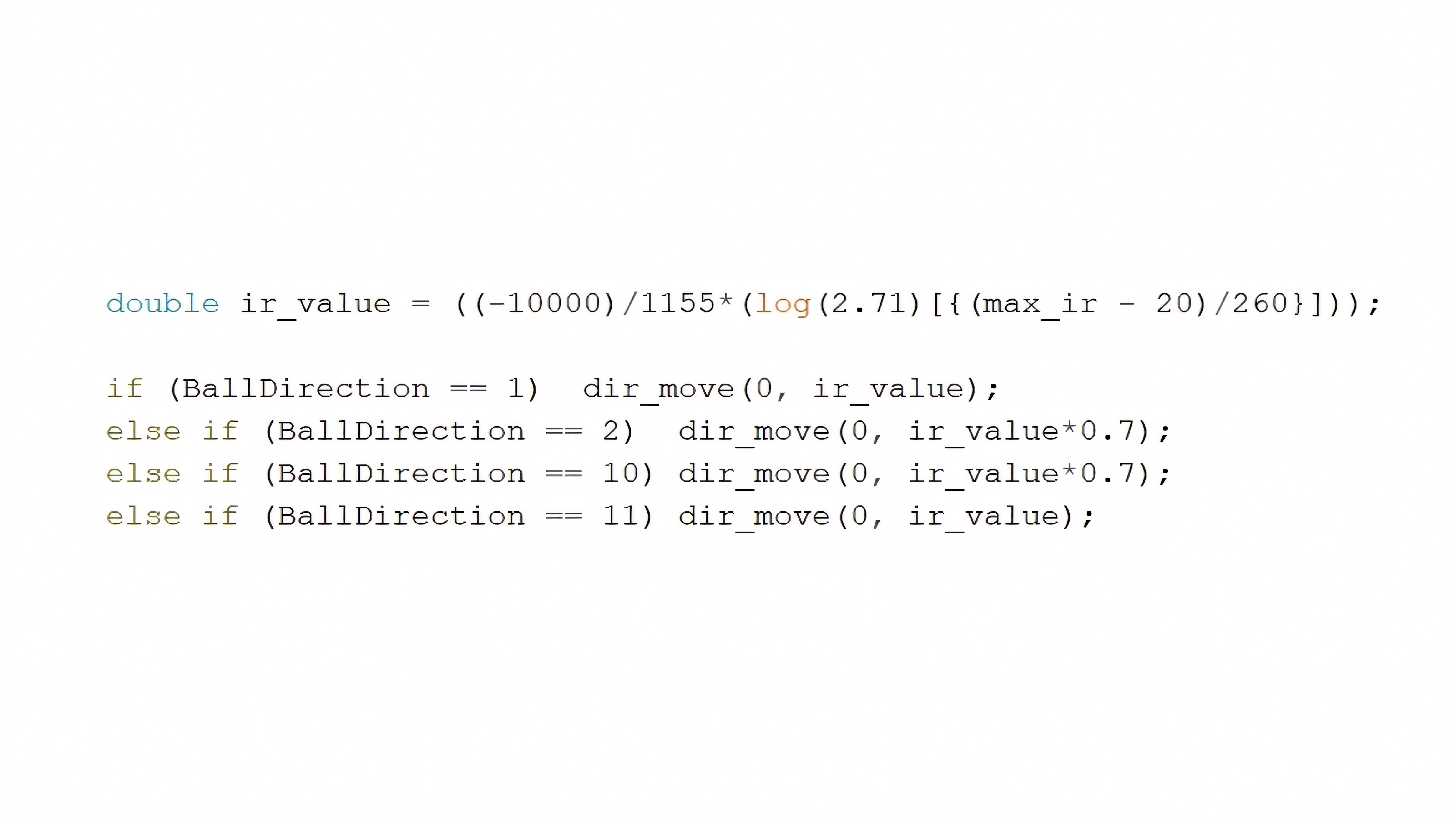
Finally, the infrared receiver-based feedback control was implemented within a limited range. More specifically, it was activated only when the ball was located at the 1, 2, 10, and 11 o’clock positions, as indicated by the BallDirection in Fig 6.b These directions correspond to the nearest positions to the ball capturing zone, enabling the robot to approach the ball with higher precision and accuracy. This infrared feedback system not only improved the stability during ball approach but also enhanced the accuracy of the ultrasonic and gyroscope-based feedback control systems.
Conclusion
This study investigated the application of sensor-based feedback control mechanisms in omnidirectional robotic systems. During the two years of experimental participation in RoboCup, the robot was iteratively improved in both hardware and software aspects.
Beginning with the Arduino based kit, a self-designed dribbling system and solenoid were later added to control the ball while driving into multiple directions. On the other hand, the hardware components were integrated with software improvements such as PID-based feedback control and inverse kinematics.
Each competition served as a validation point for the system. The robot adapted to different strategic requirements through changes in both its mechanical structure and its control algorithm. Despite limitations on the absence of encoders, the system maintained stable performance based on feedback from ultrasonic, infrared, and gyro sensors.
In June 2022, a robot equipped with a solenoid kicker and a dribbling system appeared at the RoboCup Korea Open. The hardware components were adopted after careful consideration of the dominant strategy of simple linear movement. This innovative approach introduced a new gameplay strategy to the Korean league. As a result, the team was awarded the Best Research Award highly praised the engineering effort, marking a meaningful debut in RoboCup.
This recognition secured a spot at the Asia-Pacific RoboCup Championship held in Singapore in November 2022. Due to COVID-19 restrictions, the event was conducted through technical demonstrations and interviews. The gear ratio of the dribbling system was increased to enhance rotational speed, and ultrasonic sensors were used to implement yaw angle control based on distance. Among over 800 participants from 10 countries, the team placed 2nd in the Asia-Pacific Influencer Award, which evaluates educational value, public engagement, and community contribution.
In February 2023, the team returned to the RoboCup Korea Open with an improved ultrasonic feedback control algorithm. By eliminating the variable that decides the working time, which caused the issues sticking in infinite loop, system stability was significantly enhanced. The team achieved 3rd place out of 8 teams and received another Best Research Award based on research about sensor feedback control systems on OMR.
Finally, in December 2023, the team competed again in the Asia-Pacific Championship in Pyeongchang. In this phase, the team focused on stabilizing the linear movements of omnidirectional drive systems aiming to describe the path planning technology. An inverse kinematics formula was developed to allocate motor power ratios based on gyro sensor feedback systems. Environmental awareness and control precision were significantly improved by adapting Infrared and gyro sensor feedback systems on motor control systems. In addition, the dribbler and solenoid systems operated with the highest performance throughout the whole RoboCup participation. Among 13 international teams, the robot ranked 2nd in winning points and 3rd in scoring during the first round, and 4th in winning points and 5th in scoring during the second round. The team was awarded the Best Team Description Paper Award in recognition of both technical progress and research documentation
From an academic perspective, this study demonstrated the practical application of control theory in a low-resource robotic platform. Technically, the importance of harmonizing mechanical design with algorithmic control to meet dynamic competition demands was highlighted.
A notable future direction involves integrating the dribbler and solenoid systems through a Geneva drive mechanism. This design would allow more precise control of kicking angles and ball retention timing. The Geneva structure’s ability to produce synchronized, intermittent rotation could improve performance during rapid transitions in gameplay.
This research may serve as a foundation for further development in junior-level robotics. Future versions of the robot may incorporate vision systems, multi-sensor fusion, or AI decision making.
Acknowledgement
I would like to express my gratitude to my advisors, Mr. Youn, Mr. Park, and Mr. Jeon, for their insightful guidance and continuous encouragement throughout the development of this study. I also thank the members of my robotics club Semicolon, whose collaboration and shared passion made the RoboCup Junior challenges both meaningful and rewarding. This research was made possible with the support of Guri High School, and I am deeply appreciative of the resources and opportunities provided.
Special thanks go to my friend Kwon and to Professor F.Tonidandel from Universidade de FEI, whose thoughtful feedback helped refine the experimental aspects of this study. Finally, I am sincerely grateful to my family for their support and patience during this journey.
Appendix
| Competition Date | Hardware and Mechanical Improvements | Feedback Control System | Research Focus |
| Jun 2022 (Korea Qualifier) | Upgraded to 5 kg torque, 980 rpm motors and installed initial dribbler mechanism | None | Omnidirectional mobility with enhanced motor torque |
| Nov 2022 (Asia-Pacific, Singapore) | Added solenoid and improved dribbler structure | None | Ball-handling mechanism and stability testing |
| Feb 2023 (Korea Qualifier) | Solenoid & dribbler system with sensor feedback control | P-control (Ultrasonic) | Ultrasonic-based feedback control for ball approach and field stability |
| Dec 2023 (Asia-Pacific, Pyeongchang) | Added variable resistor to dribbler for fine-tuned ball retention | P-control (Ultrasonic, Compass, IR) | Accurate directional control and improved ball accessibility |
| Type | Details |
| CPU | Arduino ATMega2560 |
| Motor | Chihai motor CHR-GM24-37 * 4, 980 RPM |
| Motor Driver | TLE5205-2G 5A H-BRIDGE |
| Wheel | 38mm Omni Wheels |
| Sensors | Arduino ultrasonic sensor * 4, GY-273 compass sensor * 1 |
| IR Receiver | IR receiver module * 12, 1500 mm resolution (600Hz ~ 2400Hz) |
| Solenoid | Takaha Kiko, CB1037 10 * 1 |
| Dribbler | 3D printed parts combined with LEGO bricks |

References
- T. Yoshimoto, T. Horii, S. Mizutani, Y. Iwauchi, S. Zenji, Asagami Works. OP-AmP 2019 extended team description paper. RoboCup Small Size League, 5 (2019). [↩]
- F. A. B. Azevedo, G. P. C. Leão, M. R. Maximo. Neural network design for a curved kicking mechanism with obstacle avoidance in RoboCup Small Size League (SSL). Journal of Intelligent & Robotic Systems, 110(3), 1–15 (2024). [↩]
- A. D. Neto, A. L. Marques, B. B. Correa, F. E. C. de Mello, G. M. R. Kashihara, G. W. Cardoso, H. B. Simoes, J. V. L. Aguiar, L. da S. Costa, N. V. Saraswati, R. M. Cukier, T. O. Aravena, F. Tonidandel, P. T. A. Junior, R. A. C. Bianchi. Team description paper 2023. RoboCup Small Size League, 5 (2023). [↩]
- M. G. Machado, J. G. Melo, C. Zanchettin, P. H. Braga, P. V. Cunha, E. N. Barros, H. F. Bassani. Planning the path with reinforcement learning: Optimal robot motion planning in RoboCup Small Size League environments. arXiv preprint arXiv:2404.15410 (2024). [↩]
- Z. Huang, Y. Wang, L. Chen, J. Li, Z. Chen, R. Xiong. Mechatronic design of a dribbling system for RoboCup small size robot. arXiv preprint, arXiv:1903.9934v1, 3 (2019). [↩]
- C. Wang, X. Liu, X. Yang, F. Hu, A. Jiang, C. Yang. Trajectory tracking of an omni-directional wheeled mobile robot using a model predictive control strategy. Applied Sciences, 8(3), 3–6 (2018). [↩]


