
Abstract
This research investigates the design and development of an actuator-powered putting mat that better replicates actual golfing conditions by varying terrain height and ball-tracking capabilities. The primary research question is to what extent an actuator-powered putting mat can simulate the topographical changes of real golfing greens to provide golfers with greater variability when using turf putting mats. In this case, success is determined by whether the mat can generate slopes similar to those commonly found on golf courses, whether changes in topography result in slopes that directly alter users’ putts, and whether the slope is consistent with typical putting greens. To address the question, a real-life model was constructed. As part of the model, twelve actuators were designed using Computer-Aided Design (CAD) technology and subsequently fabricated and programmed to reach specific heights. Control is driven through the Arduino IDE’s serial monitor. The circuit was designed utilizing microcontrollers and motor drivers. The mat’s structural components were constructed using various plastic and wood materials. Data was collected, via a Google Form, from numerous golfers to gather feedback on what they looked for most in their ideal putting mat and what improvements they believed existing putting mats needed. Results from the administered survey highlighted golfers’ preferences for ideal putting mats and the features they offer. By designing and fabricating a set of linear actuators capable of altering terrain height, the single mat could mimic a variety of slopes and curves that are accurate to those found at golf courses. Following the fabrication and testing, data on the percentages of made/missed shots on each slope were recorded and analyzed. Participants were asked to put on five different slopes (Uphill, downhill, flat, left-to-right, and right-to-left). Participants performed best on the left-to-right slope. These findings support the successful design of a terrain-changing golf mat. In the future, this model may be expanded to include statistics on users’ putts, enabling further evaluation of whether the added data benefits users.
Keywords: Terrain-changing, actuator, circuit, computer-aided design (CAD), golf mat, survey research
Introduction
Various putting mats for golf are available for consumers. Designs are as simple as the “Callaway Odyssey 8′ Putting Mat, Green”, which consists of a thin layer of turf featuring a cutout at the end serving as a hole. Such models suit players who are trying to master the fundamental basics and ball control. Other models incorporate ball-return systems that feature a direct connection between the hole and a channel used to transport the ball back to the user1. Some of the most advanced models integrate technology into their designs, enabling users to receive real-time analytics on their putts. Some mats can alter terrain heights, presenting golfers with various obstacles not typically found on ordinary mats.
This study was conducted to address the lack of terrain-changing golf mats. It aimed to develop a solution for designing a golf mat with these features, using an innovative method while ensuring ease of use for the user.
The “Perfect Practice Perfect Putting Mat”, though similar to the Callaway Odyssey mat, features distance markers and guidelines on the putting surface to help golfers develop a straight putt.
The most advanced mats on the market utilize mechanisms such as air pumps and air bags to change green terrain, as seen with the “PuttOut AirBreak Putting Mat”. This mat features eight total pumps that inflate the airbags spanning a 240 cm (8 ft) by 67 cm (2.2 ft) area. Using the pumps, the mat can create a 7.5% side slope and a 3% uphill slope. For reference, a 3% uphill slope represents a 3-ft (91.44 cm) rise for every 100 ft (3048 cm) of horizontal distance. This mat provides an accurate and realistic imitation of a putt on a golf course green. A raised platform is added to make the users’ stance level with the elevated mat. According to a report titled “Putting Green Speeds, Slopes, and “Non-Conforming” Hole Locations,” written by Jerry Lemons, Lemons cites that the recommended slope of a putting green is to 3 degrees (Or 5.24%)2.
Additionally, the entire setup folds down to 82 cm x 23 cm x 60 cm (32.28 in x 9 in 23.62 in). However, the product has many limitations. The airbags must be pumped individually, making it time-consuming for a user to adjust the slope to mimic different putts. According to a review of the PuttOut mat, published by Golf Magazine, they noted a potential drawback of the mat: durability issues. Many moving parts of the mat are made of rubber and foam. Thus, there may be weaknesses in how well parts made of such materials withstand years of use. Though the mat does tilt, the elevated platform does not, which can affect a golfer’s putting swing and stance. Issues could also arise with the length of putts, as the mat is generally designed for shorter putts.
Both the “Callaway Odyssey 8’ Putting Mat, Green” and the “Perfect Practice Perfect Putting Mat share a similarity in that they both feature an unusual slope at the end. This may make the experience feel somewhat unrealistic and affect ball speed and control. The PuttOut mat also experiences small potential issues with slope, as it can be more difficult to imitate more challenging putts on the mat over a long distance, as the limited width may limit the amount of break that putts can have.
The technology behind the mats can become even more advanced, as seen in the “PUTTR Smart Putting Green”. The mat features software and an app that can track the ball’s path, speed, and accuracy, among many other statistics. The product is also convenient, as it can be folded and stored within a box already attached to the product. However, the product poses a potential restraint due to its weight of 40 lbs when shipped to the consumer, potentially affecting its ease of use.
The surface the ball travels on is a crucial detail for all mats. Different surfaces offer different levels of friction and resistance to the golf ball, affecting ball speed. The PuttOut mat uses nylon turf, one of the closest materials to actual grass found on putting greens. Practice greens, such as the “Perfect Practice Perfect Putting Mat”, utilize a mix of velvet and felt as a substitute for turf. Velvet typically features more friction than nylon, simulating a much slower green. By contrast, nylon may simulate a quicker green. The size/length of the turf are crucial component. In a patent filed for a bunker mat for golf practice, the turf protrudes far enough upwards to the point at which more friction is generated with the golf ball, better simulating shots from deeper grass or sand3. A report by Patrick Drane, Michael Duffy, Jonathon Fournier, James Sherwood, and Michael Breed found that when a ball is hit on turf, it often skids for a portion of its initial roll4. This is important to consider when creating a realistic putting experience on turf, and further substantiates the small intricacies that must be made when choosing between putting surfaces when designing a golf mat.
Of the mats researched, each excelled in its own specific aspect. There was not one mat that combined the ideal elements. The findings of this study could aid in modeling future putting mats to achieve similar capabilities. This product can also change the way golfers practice at home. Offering a terrain-changing golf mat for at-home use lowers the need for golfers to travel to golf courses to practice on different slopes. It is worth noting that according to MyGolfSpy, the average golfer with a 15 Handicap makes 36% of putts from a distance of 6-9 ft (72-108 in).
Upon further research into patents, a patent was issued for an adjustable putting green system that used numerous small actuators. Each actuator could individually lift and lower to adjust the turf’s height5. Following deeper research, a research paper described the process of designing and powering a linear electric actuator using an Arduino and a L298N motor driver6. A similar putting green concept was applied to a driving range mat, allowing users to adjust the angle of a square mat between 0 and 20 degrees, pivoting around the center of the base7. Within the same patent, a separate, portable model consisted of 3 layers, the bottom two of which could be removed or added to lower or raise the slope.
Another patent described a turf belt with various actuators beneath the mat. Both the belt itself and the actuators could be controlled as well8. A foldable design was found within a patent for an indoor golf game and training equipment, where the base could fold over itself or roll into a compact unit9.
Upon further research on patents, a key observation made included the use of scale markings on a putting mat for improved measurements while putting and ensuring accuracy within the putting stroke10.
Furthermore, another key area of insight lies in the design of actual greens. In a report written by David A. Oats, Oats emphasizes the importance of the shape of a putting green. Smaller putting greens can face wear issues, and as they shrink, they may play differently than they were originally meant to play11. When this thinking is translated to a turf putting mat, it is important to ensure that the artificial turf is durable and does not wear out quickly.
This study aims to shed light on potential solutions to the challenges users face with existing mats. By designing a terrain-changing golf mat using linear actuators, the goal is to enhance how golfers develop their game at home. The goal of the mat is to simulate terrain changes while still optimizing transport and usability, creating a more realistic and challenging putting experience. Additionally, the cost must be minimized. A key piece to achieving this would be designing an actual 3D (three-dimensional) model that can address these objectives.
However, these goals may be impeded by resource limitations and the amount of resources used, in an effort to keep the cost and overall size of the mat to a minimum. Access to data poses another risk as the product must be tested in person, which could limit the number of participants who take part in testing the mat. Biases could also emerge if a participant testing the mat has preconceived biases towards another golf mat that they use. A participant may only put on grass putting greens on courses.
To design the mat, the methods relied on Computer-Aided Design (CAD) software, the fabrication of parts using a 3D printer, and the purchase of additional parts. Data were gathered by inviting golfers to test the mat. Participants putted on various slopes, and the number of made putts was recorded.
Methods
Actuator
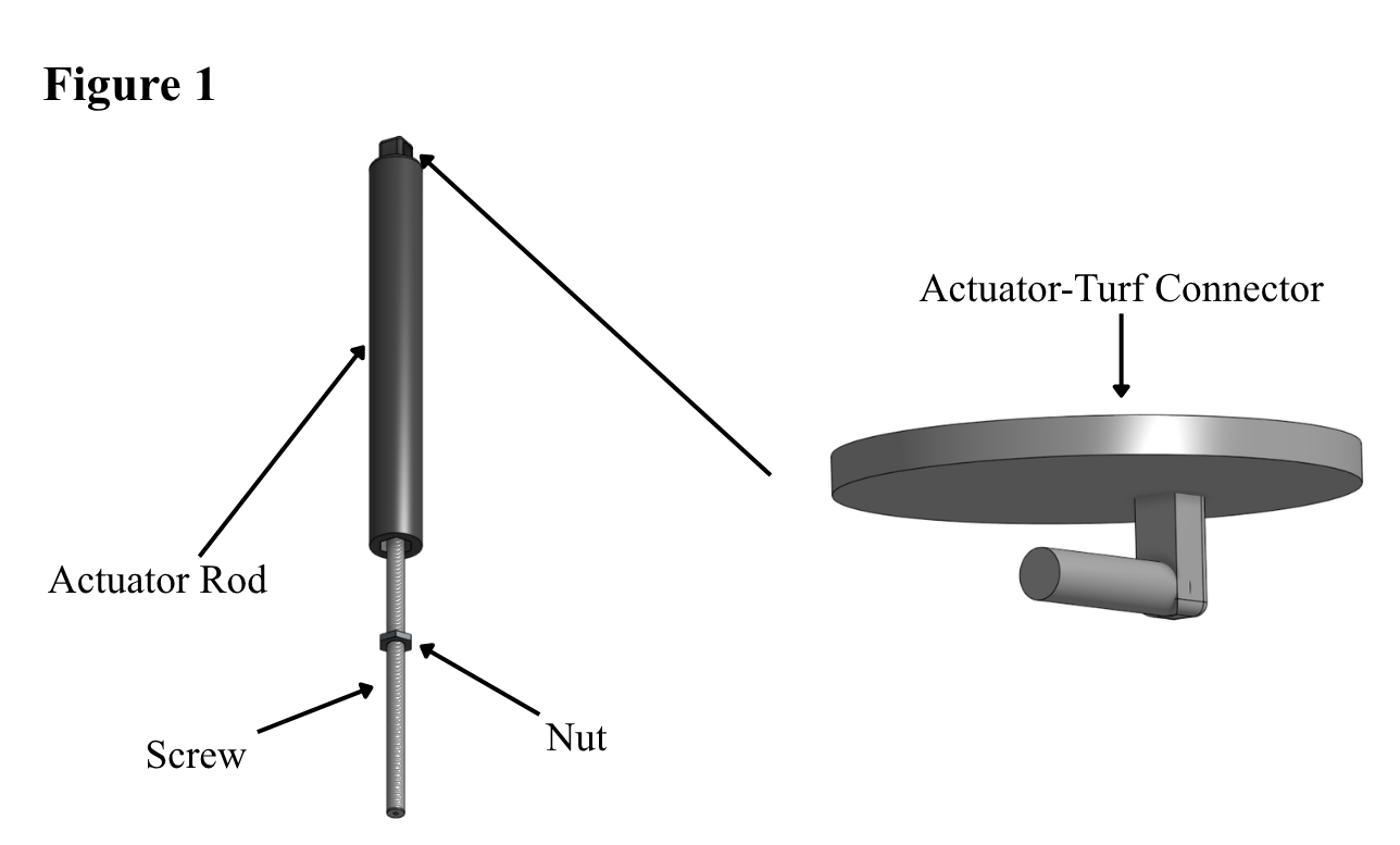
The initial actuator sought inspiration from U.S. patent US6619147B and the use of a motor that helped to drive a rotation-to-linear motion through the use of a screw and a nut, and guided via a cover with grooves12. The actuator for the mat was designed in OnShape CAD. The initial model featured a long screw that would be attached to a basic hobby motor by drilling a hole through one side of the screw for the hobby motor’s tip to be inserted into. A nut would run along the screw and be attached to the actuator’s rod portion (Figure 1). The rod would be made of PLA (polylactic acid) filament. The decision to use this filament was influenced by a study conducted by Tymrak et al in which the researchers found the average tensile strength of PLA to be 56.6 MPa (megapascals) with an average elastic modulus of 3368 MPa13. These findings demonstrate that PLA is strong in tension and a stiff filament and does not easily deform, thus supporting its use for the actuators that doubled as supports. The nut, and therefore the rod, would move up and down the screw as the motor spun. As turf would be placed on top of the actuator, the turf height would alter alongside the actuator height. The actuator rod featured a hole at the tip, allowing a separate, rotatable connection between the actuator head and turf to be added. The actuator-turf connector comprised a flat, round top (which would contact the turf) and a parallel peg below, which would slot into the actuator hole (Figure 1).
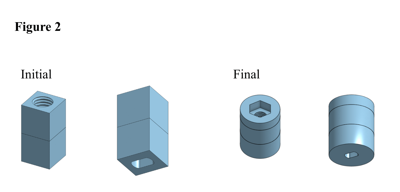
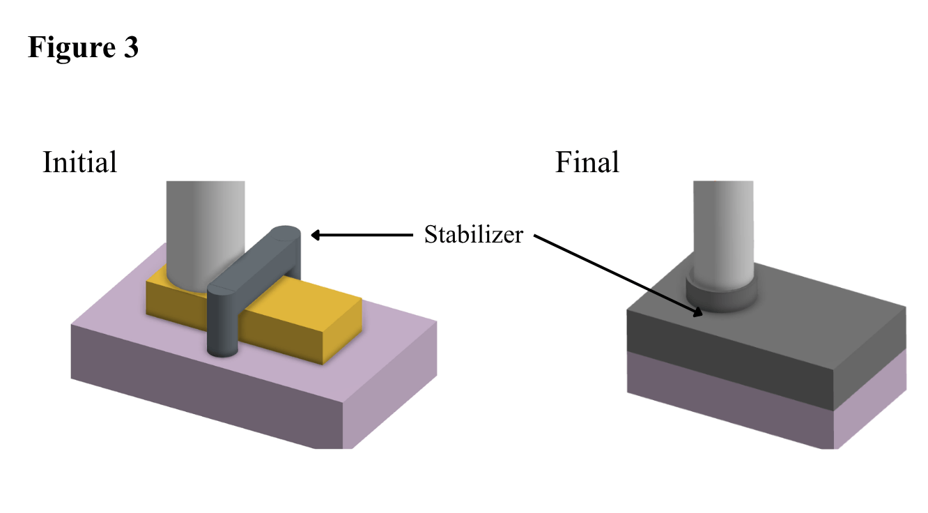
It was determined that a much larger DC (direct current) motor would improve both the balance and power of the motor compared to a hobby motor. A 3D-printed adapter was designed and printed from PLA to facilitate the connection between the DC motor and screw (Figure 2). The adapter featured a slot for the motor’s shaft and a threaded hole opposite to it to facilitate the screw connection. However, signs of instability and weakness were prominent (See Appendix A). A ground-motor connector out of PLA filament was designed and printed to allow the DC motor to lie flush with the ground (Figure 3). An additional stabilizing piece helped hold the motor in place. This stabilizing piece was modified to fully enclose the motor (Figure 3).
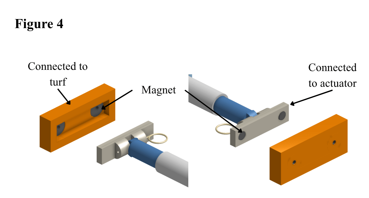
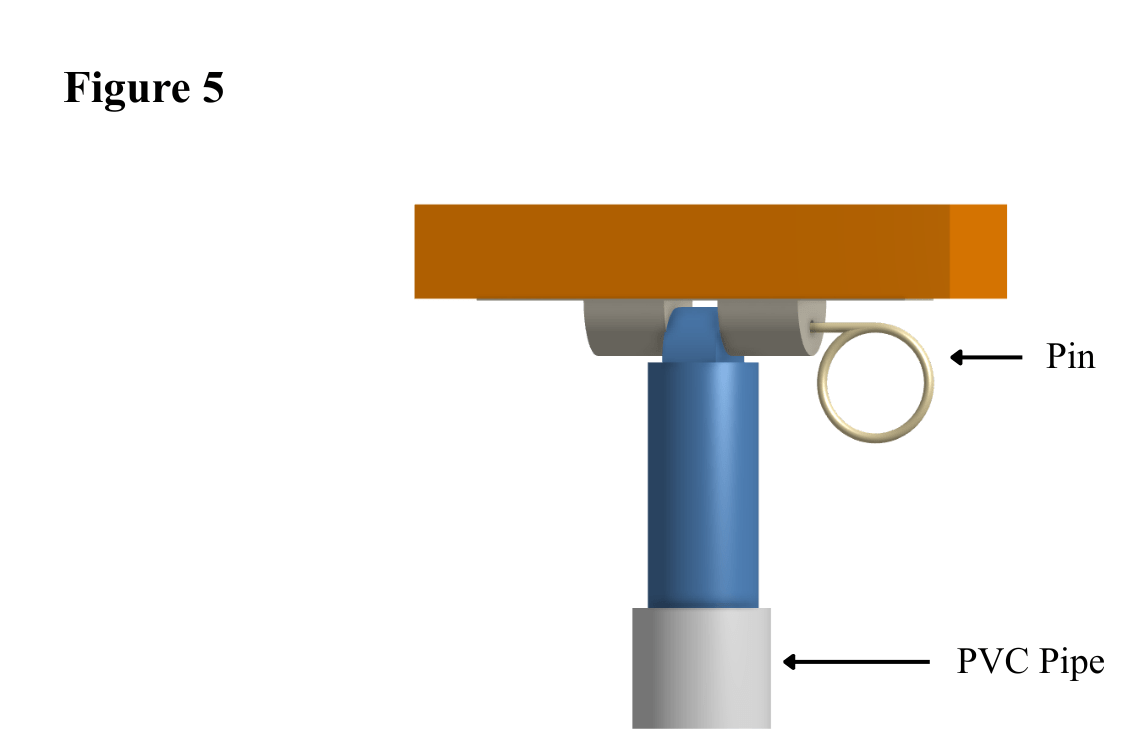
The actuator-turf connector is bulky, and its design creates a permanent connection between the actuator and turf, which could affect storability and lead to damage if stored improperly. A magnetic connection method, as used in wireless chargers, was used to connect the two parts of the actuator-turf connector (Figure 4). During testing, the magnets proved strong enough to stick to the magnets attached to the turf and weak enough to allow detachment between the turf and the actuator (See Appendix B). To further improve stability, the tip of the actuator rod was redesigned to enable a pin to be slid through the actuator-turf connector and rod tip (Figure 5).
The DC motor’s design ensured it did not sit parallel to the ground. Upon further testing, the actuator rod (In blue) became unstable and tilted as the actuator height increased. Subsequently, a piece of PVC (polyvinyl chloride) pipe was used to ensure the actuator’s rigid movement as its height increased (Figure 5).
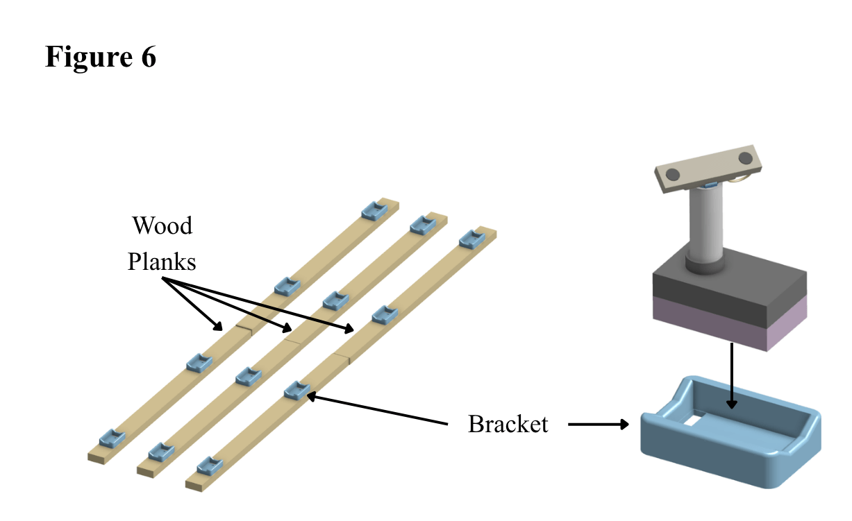
The actuator-turf connector was screwed into the turf using two screws. Three pairs of wooden planks were situated below the turf to serve as the bases of the motors (Figure 6). Each pair consisted of two 0.292-ft (3.5 in) by 4.5-ft (54 in) wood planks connected by a tee hinge, which allowed the planks to fold up. To ensure a secure hold between the wood planks and actuator, a bracket was designed using a 3D printer, allowing the connector to lodge itself in place (Figure 6). The connector itself would be directly drilled into the wooden plank.
Setup/Transportation
The mat can be detached from the twelve actuators and then rolled up for storage. The actuators require minimal storage space. They are lightweight, making a box of them easy to carry around. Actuators will be placed at the designated spots on the map (Highlighted in red) and attached to the turf using magnets to hold them in place. Holders were connected to a foldable plywood base, allowing each actuator to be easily attached and detached from the system (Figure 6).
Turf
The turf was 3.5 ft (42 in) wide, 9 ft long (108 in), and covered a total of 31.5 square ft (4,536 square in). The turf selected in particular was chosen for its ready availability, the small size of its artificial turf fibers, and its low cost. The small fibers were comparable to traditional grass on putting greens. The original dimensions of the turf were 4 ft (48 in) wide, 10 ft (120 in) long, which was the closest match to my desired dimensions. Due to the size difference, an X-Acto Knife was used to trim the turf to the desired size.
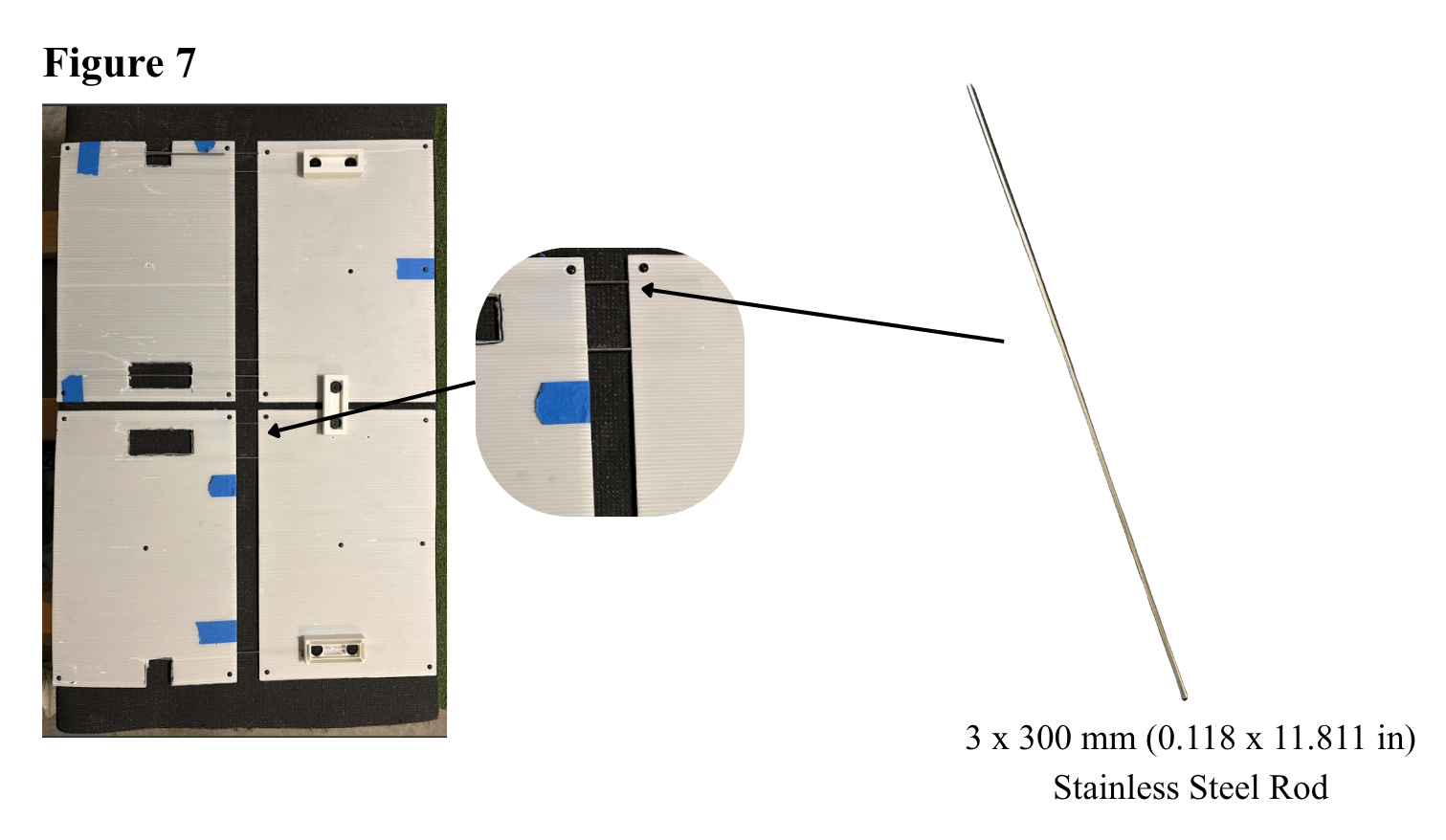
During initial testing, it became evident that the turf lacked rigidity, and it began to sag in the space between the actuators. To resolve this issue, sixteen 18” x 12” (1.5 ft. x 1 ft.) plastic poster boards were attached under the mat, and stainless steel rods were inserted through the holes in the poster boards to link them together, thereby providing more rigidity (Figure 7). The results were noticeable, and the amount of sag in the turf decreased, allowing for the putting surface to be flatter.
Circuit
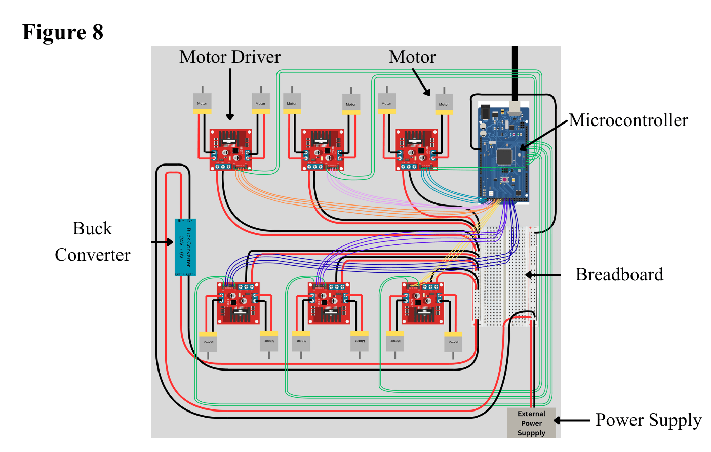
The source of power comes from a 24 Volt AC (alternating current)/DC cord. A key question during the initial circuit design was how to reduce the incoming voltage to the circuit while still allowing flexibility to raise or lower it if desired. The solution to this came after deeper research of the uses of buck converters, which convert a higher input voltage into an output voltage that is lower14. The cord connects to the breadboard before a LM2596 DC-DC buck converter that converts the 24 Volts into a stable 9 Volts to the circuit. A breadboard was used to distribute power from the buck converter to the six L298N motor drivers (Figure 8). Jumper wires were used to connect the 12 Volt and GND (ground) terminals of each of the L298N motor drivers to the breadboard’s power rails. This portion was modeled after another circuit created in a research paper in which an Arduino Uno was connected to a L298N motor driver and was able to power and control the speed of a Toshiba DGM-0090-2A DC Motor15. Another key advantage of the L298N is its speed and bidirectional vertical motion capability. As noted in research conducted by Kaffle et al., the motor controller had a time delay of less than 200 milliseconds when performing an actuate adjustment, and was able to have the motor move in clockwise and counter-clockwise directions as well16. This enabled the actuators to extend or retract rapidly, enabling terrain changes to occur with minimal delay.
Each motor driver can control two motors. As part of the motor speed control process, it was crucial to understand the function of the Arduino’s PWM (pulse-width modulation) pins. In the report “Basic DC Motor Circuits”, Gerald Recktenwald describes the purpose of PWM and its ability to supply varying power levels, while explaining how they should be used and coded on an Arduino17. The driver offered ENA (enable A) and ENB (enable B) pins, enabling speed control for the respective motors. These two pins were connected to the available PWM pins on the microcontroller. In addition, for each L298N motor driver, four jumper wires were used to connect the four digital pins to the four IN pins. This entire process was repeated six times, one for each of the six L298N motor drivers. The ground from the ELEGOO mega was connected to one of the breadboard’s ground power rails, which served as the common ground.
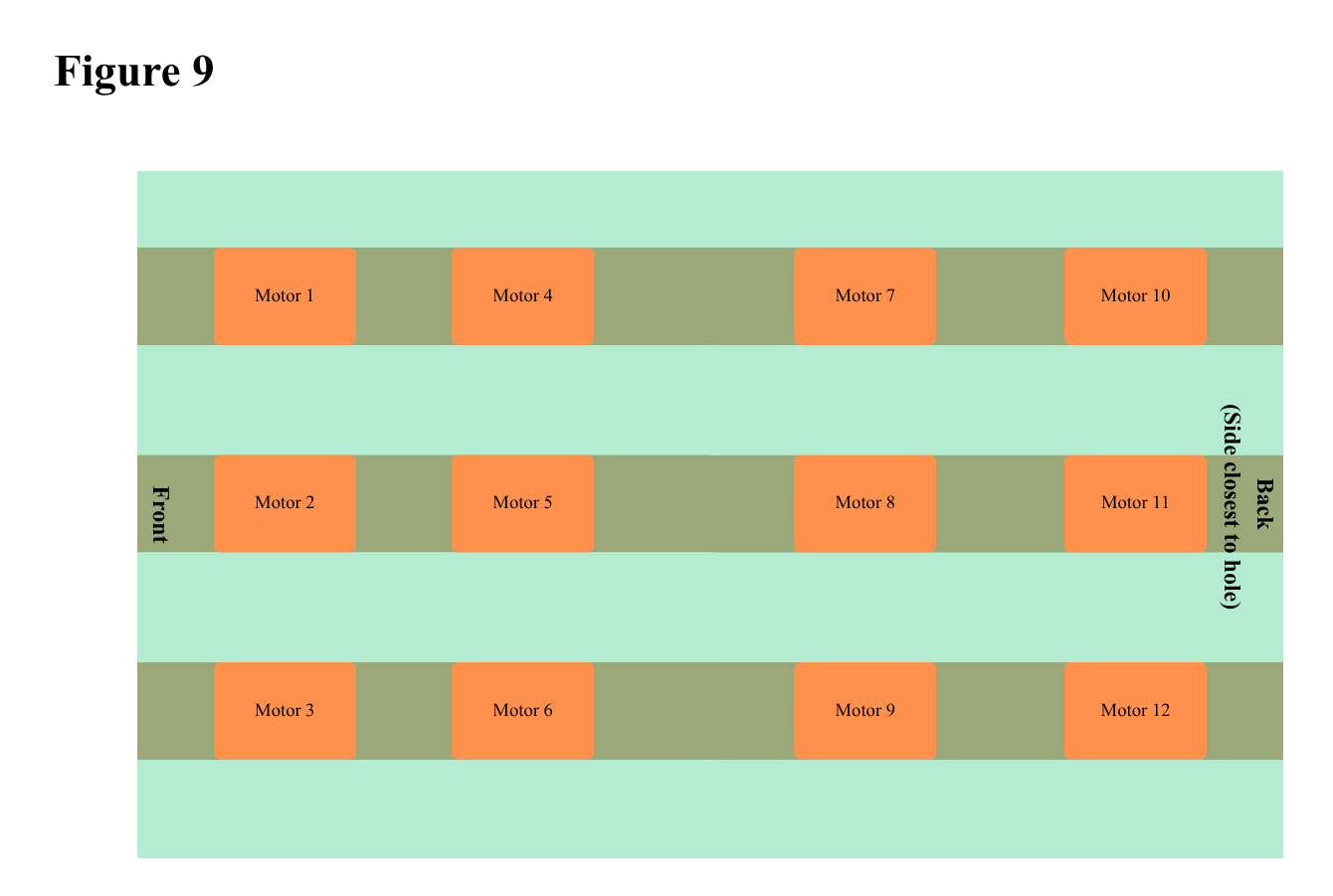
An ELEGOO Mega controls the circuit for the mat and receives power from the computer. The microcontroller has a total of 54 digital pins and 15 Pulse-Width Modulation (PWM). To control the motors, the user can use the Serial Monitor in the Arduino IDE to input the motor number (See Figure 9), followed by the direction (up or down). To stop the motor, the user inputs the motor number followed by the word “stop”. It is essential to note that the user cannot control multiple motors with a single input in the serial monitor. However, various motors can run simultaneously.
Data Collection
At the beginning of the design process, a questionnaire was conducted to gain a deeper understanding of golfers’ needs and desires, gathering information on what they sought in their ideal putting mat. The survey was optimized based on previous research on survey construction. According to the research report by Elizabeth Martin, an advantage of open questions is that they allow the survey to gather answers that may not have been anticipated by the researcher18. Open-ended questions were included in the survey, such as: “What do you dislike about existing putting mats?” Furthermore, multiple-choice questions included an “Other:” category to allow users to enter their own answers.
The questionnaire was sent to 24 golfers via SMS and text, and their experience levels varied. All respondents had prior experience either putting on grass or turf (75% said they putted on grass most, 25% said they putted on turf most). After completing the questionnaire and fabricating the mat, participants aged 14 to 59, all with prior golfing experience, tested it.
The survey asked respondents what they felt existing putting mats lacked, allowing respondents to note features to implement in the design. The survey also asked respondents to indicate how well they agreed with certain statements, such as “Putting mats should be designed to better mimic actual conditions on the course” or “I would like my putting mat to provide me statistics about my putts.” The survey provided insight into the respondents’ own preferences, such as the size of their putting mats and the material or surface they used most often.
For the survey, respondents were assured of their confidentiality. Neither emails nor names were collected during the study, and the questions were entirely anonymous. A similar process was followed during testing.
During the mat testing, 4 participants were tested, all of whom were within the researcher’s family or close circle of friends, and results were collected through observations. It is important to note that all four participants who tested the mat also filled out the survey, resulting in overlap. All 4 participants also signed an informed consent form, outlining associated risks, the time it would take, confidentiality, and obtained parental consent to be part of the study (For minors). The form also included a sample of the questionnaire and post-test survey attached.
For the experimental protocol, during testing, five different slopes were tested: A flat slope, a right-to-left slope, a left-to-right slope, an upslope, and a downslope. On all slopes besides the flat slope, the difference between the fully extended actuator and the fully retracted actuator holding up the turf was 2.5 in. Before official testing, each golfer was allowed up to 10 practice putts on slope(s) of their choosing. Each participant took 20 putts on each hill, which totaled 100 putts. The order of the five slopes on which each participant tested was random. For all participants, putts began 74 in (6.17 ft) away from the center of the hole.
Variables during the testing included putts made, putts missed, and starting distance from the hole. Additionally, the trial number and the type of slope applied by the user were recorded to better organize the data. During testing, the user would take 20 putts on each slope, using the same five balls. After the five balls were hit, those in the hole were counted and recorded on a Google Sheet. This process was repeated 4 times on each slope. After the user completed the slope, the height and angle of the slope were changed to the next slope the user would be tested on in the Arduino IDE. This process was repeated for each slope, and information on the slope type and distance from the hole was recorded. This data was interpreted and converted into percentages of putts made, which was then used to analyze which slope participants performed the best on.
Data was recorded using a Google Sheet. On the sheet, the number of makes and misses for each participant and each slope was recorded. From these, the percentage of made shots per slope was calculated by dividing the total number of made shots on the slope, regardless of participant, by the number of putts attempted in total through the same period.
Each testing participant was assigned a unique testing number to track their individual data. Throughout testing, safety was ensured by personally monitoring the circuit after the actuators finished changing heights to ensure that there was no smoking or visible damage. Each actuator was also checked after a terrain change to ensure the motors had functioned properly and that the parts were still intact.After participants completed testing, a post-test survey was administered to gather users’ thoughts on the mat, including how often they would use it per week and their opinions on potential improvements. Questions also included their own putting skill level (including handicap) and which surfaces they practiced on most frequently.
As part of the project, a Regeneron STS Institutional Review Board Approval Form was completed and signed by a registered nurse, a school administrator, and an educator not involved in the project. The project will be submitted for the Society of Science (STS) when the 2027 cycle reopens.
Results
After conducting a study that gathered 24 responses, all from golfers, one consistent change respondents said they would make to existing putting mats would be to incorporate various slopes/breaks. Of the respondents, 82% either agreed or strongly agreed that putting mats should be better designed to imitate actual putting surfaces and conditions. To highlight further continuity, 82% of respondents felt putting on a putting mat was not the same as putting on an actual green. Most respondents also expressed a desire to place mats to record statistics on their putts. Of the survey’s participants, 75% stated that they putt on grass surfaces the most. Furthermore, on a scale from 1 to 5 (where 1 indicates the respondent never uses a putting mat to practice and 5 indicates they always use one), 21.7% selected 1, and no respondents selected 4 or 5.
When asked about the size of their desired putting mat, 50% of respondents stated that a width of 3.5 ft (42 in) was their ideal. The second most desired size was 3 ft (36 in) wide, to which 29.2% of respondents indicated it as their preferred size. In addition, 54.2% of respondents stated that their desired putting mat would be 9 ft (108 in) long (S1). Through the responses, it was evident that respondents sought the ability to adjust the slope of the mat, a feature not commonly found in existing putting mats, as mentioned in the introduction. It is important to remember that the survey results are indicative, not representative of all golfers.
During testing, each of the four participants putted on each of the slopes. For reference, participants’ handicaps were as follows: 6.6, 20, 15, and N/A (N/A indicates the golfer was unsure of their handicap). 3 respondents stated they putted more frequently on a grass putting green, while 1 stated they putted more often on turf. When asked how often they typically putted a week, respondents reported once, twice, three times, and five times. Such data was collected from the post-test survey.
Participants performed the highest on the left-to-right slope, where an average of 41.25% of putts were made. By contrast, the slope(s) with the lowest average were tied between the flat slope and the downhill slope, where only 20% of putts went in. The right-to-left slope was slightly higher, with an average percentage of 21.25%. The uphill slope had a 27.5% putt-in rate.
For the flat slope, throughout the 4 participants, the mean for putts made was 4, the sample standard deviation was 2.8284, and the 95% confidence interval was 4 +/- 2.772. For the right-to-left slope, the mean putts made was 4.25, and the sample standard deviation was 3.594. The 95% confidence interval was 4.25 +/- 3.522. For the Left-to-right slope, the mean was 8.25 putts made, and the sample standard deviation was 4.5, while the 95% confidence interval was 8.25 +/- 4.41. For the uphill slope, the mean was 5.5 putts made, the sample standard deviation was 4.4347, and the 95% confidence interval was 5.5 +/- 4.346. Lastly, for the downhill slope, the mean was 4 putts per participant. The sample standard deviation for the downhill slope was 2.4495 with a 95% confidence interval of 4 +/- 2.40.
The mat could reach a maximum grade of 5.95% (From the left edge of the turf to the right edge of the turf, or vice versa) on right-to-left and left-to-right slopes. On such slopes, the difference between the height of the fully extended actuator and the fully retracted actuator was 2.5 in. This difference was the exact same for downhill and uphill slopes; however, the percent grade was 2.31% downhill or uphill.
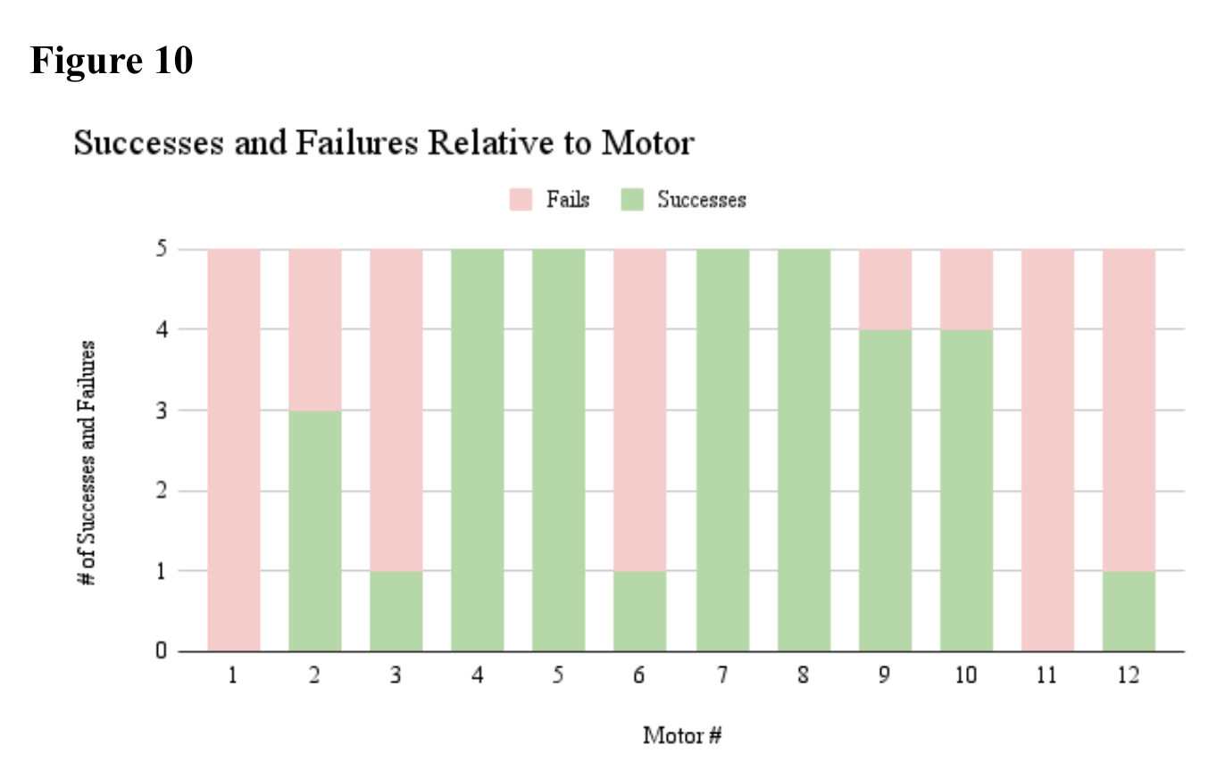
During testing, the mat had varying consistency. One issue that arose with some motors was when the screw and rod of the actuator wound down, the actuator rod failed to (As the nut on the screw was not securely attached to the actuator rod), and therefore the turf itself did not. This meant that, occasionally, the mat had to be pushed down by hand in some areas. Specific testing was conducted to address how widespread the issue was. Each motor was tested individually 5 times to determine its ability to raise and lower (See Figure 10). Only motors 4, 5, 7, and 8 consistently moved up and down without assistance throughout the 5 trials. Motors 1 and 11 failed to move up and down at all without having to be pushed down by an additional force. It is important to note that testing was conducted over 5 trials per motor, and the data may not reflect operation over an extended period of time, but it provides a solid glimpse of consistency.
One key aspect this mat offers that others don’t is terrain-changing capabilities via actuators, while remaining an easily collapsible system that retains structural integrity in use. This product contributes to understanding the potential mechanisms of terrain-changing golf mats. Other mats, such as those mentioned in the introduction, are not elevated off the ground and are restricted in the terrain that they can cover. Such devices that can change terrain require a physical action to do so.
The addition of terrain-changing capabilities allows users to practice putting on various slopes from the convenience of their own homes. The device is also unique in that it has a large number of different slopes that it can generate as the actuator’s height is dictated by turning the motor on and off, rather than having the actuator reach a specified height, a key advantage of using such a mat. A key disadvantage of this setup is that the slopes are not highly reproducible, which is important to consider when interpreting the testing results. The only guarantees for the same heights are when the actuator is fully retracted or extended.
Discussion
There is no evident correlation between the limited success of the flat, downhill slopes and the sag between the actuators. However, observations during testing showed that the sag disrupted the ball’s roll consistency, making it difficult to find the proper putting speed.
While the actuators simultaneously served as supports, holding the turf up, they were unable to prevent sagging. Though reinforcement measures, in the form of boxes, were placed under the mat to level out the turf when it was flat, when portions of the turf were raised on other slopes, dips in the mat were visible. This observation highlights the potential drawbacks of such a design, as it can be more challenging to achieve flatter slopes without additional supports. Furthermore, the slopes, though they were the same in general, were not exactly the same due to the inability to reproduce slopes as mentioned above. The data in the results should thus be interpreted with this in mind.
Respondents likely sought terrain-changing features in a putting mat because there was a limited number of existing products with such abilities. Existing mats often lack realism when compared to actual course conditions. This may lead many golfers to seek a better option. In addition, it is easy to create any slope from home. This highlights the convenience aspect of the golf mat. Survey respondents likely favored a mat length of 9 ft (108 in) because it falls between extremely short and extremely long, allowing users to putt at realistic distances typically found on a course. The width of 3.5 ft (42 in) likely reflects the user’s desire to allow for extra space to curve shots along a slope. It also shows a desire to have a wider range of places to putt from.
Through research and design, a functioning terrain-changing golf mat was successfully designed and fabricated. The mat provided users with a variety of slopes all in one mat, something that most traditional putting mats could not. As for transportation, the mat could be disassembled into various components, which could be easily stored; however, the weight of the wooden planks made it difficult to transport.
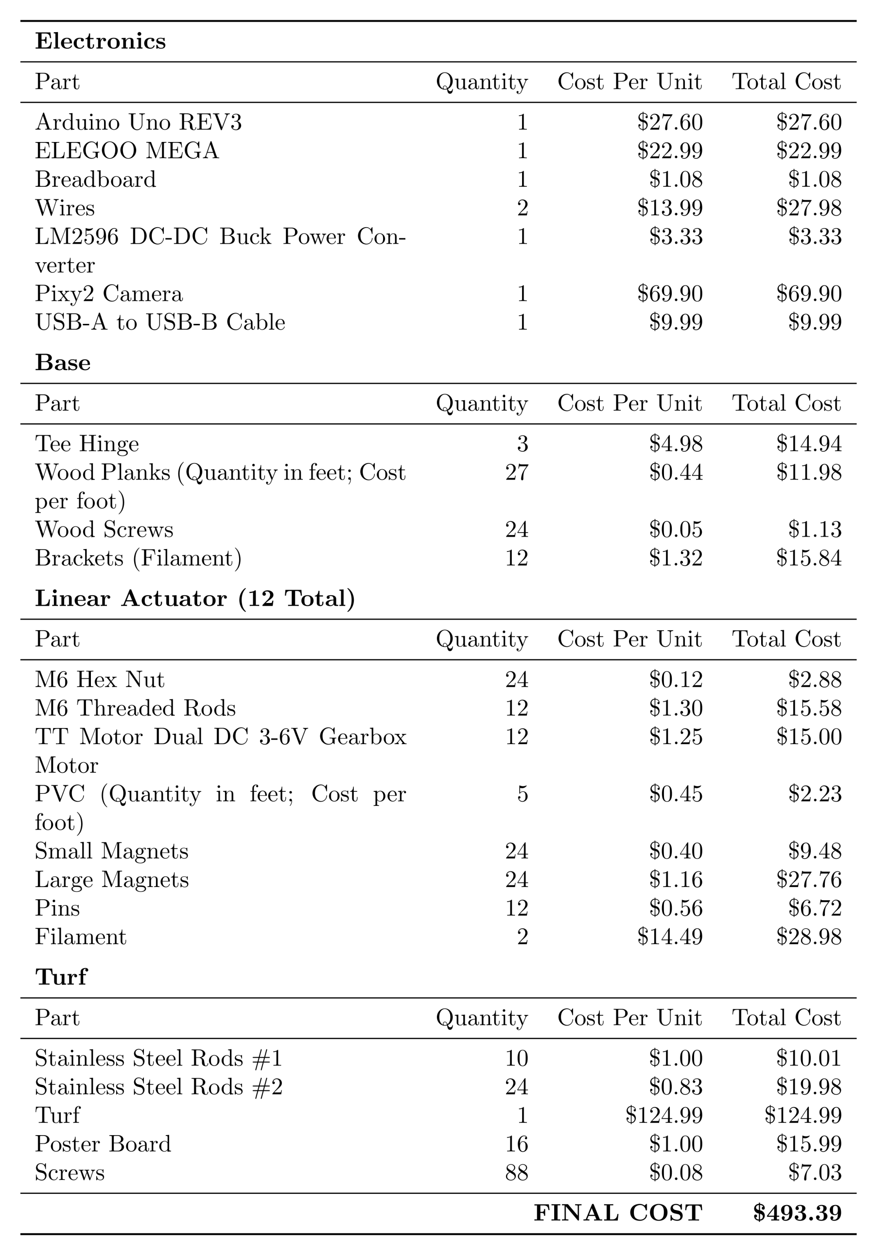
Some goals that were not achieved included keeping costs low. The average price for the mats mentioned in the introduction was $182.39. The cost for all the materials needed for this mat was $493.39 (See Figure 11). Costs can be reduced during mass production by bulk purchasing parts, lowering the cost per unit. Furthermore, portions of the design can be simplified. The poster board and stainless steel rods can be simplified by using a more rigid turf or by using a single material beneath the turf. Simplifying the base of the putting mat by designing individual, stable supports for each actuator will also help reduce the amount of wood and screws used. It is still important to prioritize structural strength over cost-cutting to ensure the product remains functional.
The low percentages of made putts on the mat are in roughly the same range of actual putting percentages at near similar distances for golfers on typical golf courses, as mentioned in the introduction. Traditional putting mats would likely see much higher percentages because the flat mat results in the same or very similar straight putts every time. Furthermore, the slope established by the mat met the standards of putting greens commonly found on golf courses, and throughout testing, the mat showed no evident signs of wear. During testing, skidding was not evident; further testing may be conducted to determine whether it is present and, if so, the extent.
Since the confidence intervals vary widely across groups and many overlap, the differences in slopes are likely due to random variation. To improve upon this in the future, the sample size could be increased to add more data and to alter the mean, standard deviation, and confidence interval to yield more meaningful results.
This research can inform future product development, particularly for golf mats or other general applications of terrain-changing technology. Further investigation could be completed in the area of ball-tracking capabilities. Users may benefit from further modifications to the mat down the line, including the provision of statistics on their ball speed, break, and launch angle. This could allow golfers to analyze their putting stroke and make adjustments. Existing products such as the Putt.It.In device are capable of measuring backswing and front swing distance, clubhead speed, and swing angle using an accelerometer and pulse sensor19. In addition, the concept of using actuators to control the height or shape of a surface has potential for further application to molding, treadmills, and products designed to improve posture.
Additionally, more supports could be added to the mat in the future to reduce the existing sag in the turf between the current actuators and support the weight of a person standing on the mat. Currently, a box can be placed below the mat or along the side of the mat for the user to stand on while putting. The added supports would be placed between the existing actuators’ columns. In addition, the turf tends to sag along the edges; therefore, added reinforcements could be incorporated into the mat to stiffen the edges. The individual actuator components could be made of a more durable material, such as stainless steel. This would improve the overall structure of the actuators and prevent them from leaning during use. U.S patent US6623371B2 patents the use of a golf ball return system in which there is a chute at the end of the turf which connects to a return gutter. A similar chute is connected from the hole to the gutter20. With this in mind, a similar ball-return system could be implemented using flexible pipes, reducing the need to fabricate a gutter. Furthermore, a ball dispensing system similar to that of U.S. patent US6328659B1 could be incorporated alongside the mat in order to reduce the need of the user to individually place the ball, thus improving user friendliness, and minimizing extra movement21. In addition, a backstop similar to the one implemented in the golf training device described in the patent US20030207716A1 could be scaled down to catch putts and prevent balls from rolling off the end of the mat22. Improving the consistency of the actuators’ ability to raise and lower would be another area for improvement, helping address durability issues with existing mats.
Outside the mat itself, one of the many improvements that could be made to the system later on would be to enable ball tracking and statistics (e.g., ball speed). This may help improve the user’s overall putting experience. Current methods of ball detection in sports include the use of YOLO (You Only Look Once), and R-CNN algorithms, among many other algorithms. These advanced systems may be implemented into future versions that incorporate more advanced software and faster tracking23. These methods contrast with a traditional Pixy camera, which relies on color-based detection and is a suitable alternative for the initial model due to its ease of use and low cost. In addition, it has object-tracking capabilities and is compatible with Arduino and the Arduino IDE. Among other improvements, implementing a remote control for the mat itself would enhance the mat’s functionality and ease of use compared to the current process. Furthermore, the current ease of use of the Arduino IDE UI for ordinary users has not been achieved, as multiple motors cannot be moved with a single UI action.
While the mat can create a variety of slopes, the research on the human response and the causes of patterns of makes and misses depending on slope has yet to be fully understood. Research conducted by Robbins et al. 2025 found that changes in the incline and distance from the hole when putting can lead to kinematic alterations, such as axial-trunk rotation and head extension, in the body and putting stroke24. Further research on this topic could help provide more insight into why participants performed better or worse on certain slopes.
To conclude, the goal of this research was to design a terrain-changing putting mat that has an infinite range of slopes, while being dismantable and transportable. The mat’s goal is to mimic realistic putting conditions that go beyond typical flat terrain, a common feature of existing mats on the market. The development of the mat can be divided into four distinct phases: CAD design, fabrication, circuit design, and programming. Twelve motors were designed in total, each of which can be controlled via the Arduino IDE. The final product consists of a functional proof-of-concept mat capable of forming multiple slopes, though further work is required to achieve a finalized product.
Acknowledgements
I would like to acknowledge my mentor, Alex M. for providing feedback and insights on the design elements of the golf mat and circuit. I would like to acknowledge my mentor, Nathantial B., for providing support and guidance throughout the submission process.
Appendix
A – Weakness was found especially at the DC motor-screw connection, where the thin adapter supported the large actuator rod. The adapter was revised to ensure it was flush with the actuator rod.
B- The actuators required a connection method that would allow detachment while remaining strong enough to remain connected to the mat during operation. The connector consisted of two separate parts: one attached to the turf via screws protruding through holes in the part, and the other attached to the actuator. Both parts of the connector were 3D-printed in PLA. The indented part would be screwed directly onto the turf while the other part would remain connected to the actuator.
Supplementary Materials
References
- Paton, William, and Individual. US20230041683A1 – Golf Ball Returning Device From Both a Golf Net Training Device and a Putting Training Device – Google Patents. 6 Aug. 2021, patents.google.com/patent/US20230041683A1/en?q=(Golf+ball+return)&scholar&oq=Golf+ball+return. [↩]
- Lemons, Jerry. Putting green speeds, slopes, and “Non-Conforming” hole locations. journal-article, June 2008, gsr.lib.msu.edu/2000s/2008/080721.pdf. [↩]
- Park, Jung Hak, et al. WO2011065803A2 – Bunker Mat for Golf Practice – Google Patents. 30 Nov. 2009, patents.google.com/patent/WO2011065803A2/en?q=(Golf+mat)&scholar&oq=Golf+mat. [↩]
- Drane, Patrick, et al. “The Behavior of Golf Ball Putting on Artificial Turf.” Procedia Engineering, vol. 72, 2014, pp. 599–604, https://doi.org/10.1016/j.proeng.2014.06.107. [↩]
- J. G. Flammer and D. Llc, “US11103759B2 – Adjustable putting green system and method thereof – Google Patents,” Sep. 08, 2012. https://patents.google.com/patent/US11103759B2/en?q=(putting+green)&oq=putting+green. [↩]
- Jesús Antonio Nava-Pintor, et al. “Design, Implementation, and Control of a Linear Electric Actuator for Educational Mechatronics.” Machines, vol. 11, no. 9, 8 Sept. 2023, pp. 894–894, www.mdpi.com/2075-1702/11/9/894 , https://doi.org/10.3390/machines11090894. [↩]
- Tomczyk, Michael. “US20020187848A1 – Adjustable Golf Practice Mat – Google Patents.” Google.com, 31 Jan. 2001, patents.google.com/patent/US20020187848A1/en. Accessed 1 Apr. 2026. [↩]
- A. M. Claessen, J. L. Kuiper, and Individual, “US10610734B2 – Configurable flexible golf putting green system and methods – Google Patents,” Mar. 31, 2016. https://patents.google.com/patent/US10610734B2/en?q=%28putting+green%29&oq=putting+green. [↩]
- Green, Stephen W., et al. US8287395B2 – Indoor Golf Game and Training Equipment – Google Patents. 23 Nov. 2009, patents.google.com/patent/US8287395B2/en?q=(Golf+mat)&scholar&oq=Golf+mat. [↩]
- Shin, Sam-Kyu, and Individual. US20060040761A1 – Scale Mark Mat for Putting Practice – Google Patents. 23 Aug. 2004, patents.google.com/patent/US20060040761A1/en?q=(Golf+mat)&scholar&oq=Golf+mat&page=8. [↩]
- Oatis, David A. “The Evolution of a Putting Green.” The Evolution Of A Putting Green, 14 Feb. 2015, www.usga.org/articles/2010/03/the-evolution-of-a-putting-green-2147485896.html. [↩]
- US6619147B1 – Linear Actuator – Google Patents. patents.google.com/patent/US6619147B1/en?oq=US+6%2c619%2c147+B1. [↩]
- Tymrak, B. M., et al. “Mechanical Properties of Components Fabricated With Open-source 3-D Printers Under Realistic Environmental Conditions.” Materials & Design (1980-2015), vol. 58, Feb. 2014, pp. 242–46, doi:10.1016/j.matdes.2014.02.038. [↩]
- Ejury, Jens and Infineon Technologies North America (IFNA) Corp. “Buck Converter Design.” Design Note DN 2013-01, Jan. 2013, pp. 1–7, cdn.badcaps-static.com/pdfs/2a997c023d0eda74b0a3c42d4b38ca9c.pdf. [↩]
- Mahar, Aiman, et al. “DC Motor Speed Control Through Arduino and L298N Motor Driver Using PID Controller.” ResearchGate, July 2022, www.researchgate.net/publication/361763175_94-Article_Text-198-1-10-20211204. [↩]
- Kaffale, Tesfaye Hordofa, and Jia Liu. “Speed and Direction Control of DC Motor Using Arduino Uno Microcontroller.” OALib, vol. 12, no. 03, Jan. 2025, pp. 1–11, doi:10.4236/oalib.1113007. [↩]
- Recktenwald, Gerald and Portland State University. “Living With the Lab: Basic DC Motor Circuits.” Living with the Lab, 2012, pp. 1–15, cdn.sparkfun.com/assets/resources/4/4/DC_motor_circuits_notes_2up.pdf. [↩]
- Bureau, US Census. “Survey Questionnaire Construction.” Census.gov, 21 Dec. 2006, www.census.gov/library/working-papers/2006/adrm/rsm2006-13.html. [↩]
- Taha, Zahari, et al. “The Development of the Putt.It.In Monitoring Device and the Establishment of Its Reliability: A Solution for Putting-In Analysis in Golf.” Movement Health & Exercise, vol. 6, no. 1, Jan. 2017, doi:10.15282/mohe.v6i1.136. [↩]
- Corcoran, Jerry A., and Individual. US6623371B2 – Golf Putting and Ball Return System – Google Patents. patents.google.com/patent/US6623371B2/en. [↩]
- US6328659B1 – Golf Ball Dispensing and Teeing Device – Google Patents. patents.google.com/patent/US6328659B1/en?q=(automatic+golf+ball+dispenser)&oq=automatic+golf+ball+dispenser. [↩]
- Bradstock, Alden, and Individual. US20030207716A1 – Golf Swing, Chip, Pitch or Putt Practice and Training Device – Google Patents. 15 June 2000, patents.google.com/patent/US20030207716A1/en?q=(Golf+ball+return)&scholar&oq=Golf+ball+return. [↩]
- a Moreira, Cristiano, et al. “A Comprehensive Review of Ball Detection Techniques in Sports.” PeerJ Computer Science, vol. 11, Aug. 2025, p. e3079, doi:10.7717/peerj-cs.3079. [↩]
- Robbins, Shawn M., et al. “Kinematic Alterations With Changes in Putting Distance and Slope Incline in Recreational Golfers.” Bioengineering, vol. 12, no. 1, Jan. 2025, p. 69, doi:10.3390/bioengineering12010069. [↩]


