
Abstract
The need for sustainable and localized energy solutions has led to a growing interest in small-scale wind turbines (SSWTs), particularly for urban and remote areas. However, improving their efficiency and cost-effectiveness remains a critical challenge. This paper presents a comprehensive review of optimization techniques and simulation tools aimed at enhancing SSWT performance. Drawing on case studies such as those by Civelek and Kalkan (2020) and Cao (2011), the study analyzes real-world applications and field data to evaluate design effectiveness. Key aerodynamic and mechanical factors such as rotor diameter, blade shape, pitch control, axial induction factor, and angle of attack are identified as major contributors to energy output. Blade Element Momentum Theory (BEMT), Betz’s Law, and Glauert’s corrections are discussed as foundational models in blade design. Simulation platforms including MATLAB, ANSYS, and Autodesk Fusion 360 are examined for their role in prototyping and testing, proving to be helpful tools. Control algorithms like PID controllers and optimization methods such as Genetic Algorithms (GA) significantly enhance power regulation. In Permanent Magnet Synchronous Generator (PMSG) systems, Maximum Power Point Tracking (MPPT) using the Perturb and Observe method demonstrated a 50.77% increase in power output. The study also explores emerging trends such as AI-based wind forecasting, urban turbine integration, and hybrid materials. These advancements are crucial for making SSWTs more viable in diverse environments.
Keywords: Small-scale wind turbine, pitch control, Blade Element Momentum Theory, rotor design, optimization, MPPT, urban wind energy
Introduction
Background and Importance of Renewable Energy
Energy production and consumption remain central concerns globally, especially with the increasing urgency of climate change. Scholars and engineers are actively researching which energy technologies are clean, efficient, economically viable, and globally scalable.
Among renewable sources, wind energy stands out due to its high scalability, low operational cost, and low environmental impact. Historically, wind power was harnessed as early as 200 BC through mechanical windmills, primarily for milling grain or pumping water. Modern technologies have transformed these systems into wind turbines, which convert kinetic wind energy into electrical energy through mechanical means.
Overview of Wind Energy and Small-Scale Wind Turbines
Nowadays, wind energy is harnessed by wind turbines, but what are they? Wind turbines are those which convert the kinetic energy present in the wind to mechanical energy and eventually into electricity. Reasons why it is being pursued are because it is clean, renewable and sustainable being feasible for the environment. They can easily be scaled to produce a mass amount of energy without much damage to the environment.
Advantages of Small-Scale Wind Turbines
Small scale wind turbines, also known as Micro Wind Turbines (MWTs), with rotor diameters ranging between 3–10 meters and power output up to 100 kW1, seems to be a practical solution for off-grid applications. These turbines are suitable for rural and suburban areas, where wind is less obstructed and land availability is higher. Their comparatively simple installation and lower cost compared to large-scale farms make them attractive for localized energy generation.
Purpose and Scope of the Study
The purpose of this paper is to explore the latest advancements in the design, optimization, and simulation of small-scale wind turbines, with a focus on improving their performance, efficiency, and economic viability. By reviewing current technologies, simulation tools, and field data from real-world case studies, this study aims to identify key parameters—such as rotor diameter, blade shape, pitch control, and aerodynamic factors—that significantly influence turbine output. Additionally, the paper highlights future trends and challenges in the wind energy sector, including urban integration, AI-driven optimization, and sustainable material use
Methodology
Literature Search Strategy
The literature review relied on academic databases such as ScienceDirect, ResearchGate, and Google Books. Keywords such as ‘small-scale wind turbine’, ‘blade optimization’, ‘wind energy simulation’, and ‘performance analysis’ guided the search.
Criteria for Source Selection
The selection criteria emphasized relevance to small-scale systems, practical efficiency gains, and adaptability to environmental variations. Additionally, papers providing mathematical modeling or simulation-based evaluations were prioritized. Approximately 20 core papers were shortlisted. These include broad reviews, such as A Review on Small Scale Wind Turbines; region-specific studies like a performance analysis2; optimization studies for low-speed conditions3‘4. Together, they provide a foundational understanding of design intricacies and implementation challenges.
Review Scope and Limitations
As a small reference to understand the types of small scale wind turbines without going deep into the details: A review on small scale wind turbines – ScienceDirect
A case study which is relevant to the topic: Aerodynamics Analysis of Small Horizontal Axis Wind Turbine Blades by Using 2D and 3D CFD Modelling Han Cao
A Giant catalogue of wind improvements over the years: Advances In Wind Power
Optimization Of wind turbines for low speed: Optimization of Small Scale Wind Turbine Blades for Low Speed Conditions
A Performance analysis on SWTS: A small wind turbine system (SWTS) application and its performance analysis – ScienceDirect
Literature Review
Nacelle and Rotor System
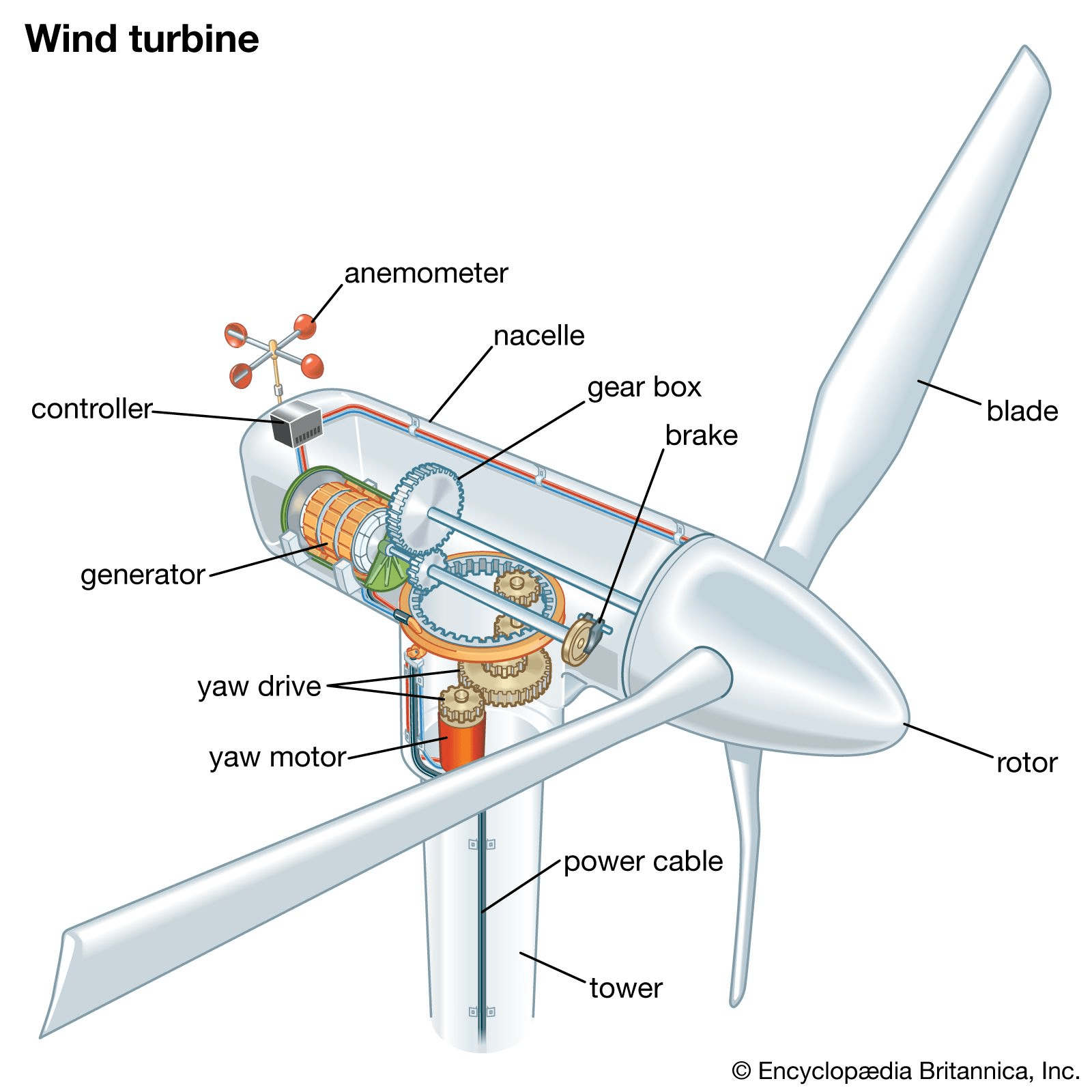
The box-like nacelle module is considered the heart of a wind turbine. It sits on top of the tower and is connected to the rotor. The nacelle is usually made of fiberglass and houses the drivetrain. It changes direction with the help of its yaw drive system. The rotor system converts the slow-speed mechanical energy into three-phase alternating current through a gear system and a generator5.
Blade Structure and Airfoil Design
The blade structure is responsible for the amount of lift and drag created by the wind turbine, allowing it to rotate more during slow speed wind conditions5.
Tower and Tail Components
Tower: The placement, height and materials are very important factors which can save costs and increase power output. All these factors are indispensable when determining the creation of the tower, which is also the base for the wind turbine5.
Tail component: It changes the wind turbine direction and accommodates the variation of the oncoming direction of wind, allowing it to generate more energy during low speed conditions and turn in a safe direction during very high speed wind conditions5.
Horizontal vs. Vertical Axis Turbines
HAWTs (Horizontal-Axis Wind Turbines) have a horizontal axis of rotation, requiring a yaw system to optimize wind direction, while VAWTs (Vertical-Axis Wind Turbines) feature a vertical rotor shaft and can generate energy from all wind directions without needing a yaw system6.
| Aspect | HAWTs (Horizontal-Axis Wind Turbines) | VAWTs (Vertical-Axis Wind Turbines) |
| Directionality | Can only use wind from a given direction and require a yaw system to optimize orientation. | Can generate energy from all wind directions; do not need a yaw system. |
| Efficiency | More efficient as they reach higher wind speeds at greater heights. | Less efficient; operate closer to the ground where wind is slower and more turbulent. |
| Installation | Installed on tall towers; complex and more expensive to maintain. | Installed closer to the ground; easier and cheaper to maintain. |
| Applications | Suitable for large wind farms and commercial energy production. | Ideal for residential or small-scale local energy production. |
Recent studies compare HAWTs and VAWTs and provide insight for their applications. HAWTs achieve higher efficiency( reported efficiency difference of approximately  ) due to their ability to access faster, less turbulent winds at greater heights. They are thus ideal for large-scale energy production. VAWTs capture wind from all directions without a yaw system ( can produce higher torque ) and offer simpler installation and higher torque at lower wind speeds. This can be advantageous for small-scale or urban applications8.
Performance Analysis and Simulation Tools
ANSYS (CFD and FEA Capabilities)
Airflow Modeling: Computational fluid dynamics (CFD) simulations are frequently performed using ANSYS. By simulating the intricate airflow surrounding wind turbine blades, it can shed light on efficiency, turbulence, and aerodynamics. In order to optimize the design for optimal energy capture, ANSYS Fluent excels in simulating the interaction between wind and rotor blades.
Evaluating Structural Stress: ANSYS offers strong finite element analysis (FEA) capabilities for evaluating wind turbine component structural integrity. The program can model the effects of gravity, wind, and other environmental forces on the turbine’s frame, blades, and tower, assisting in the optimization of material use and the identification of possible failure locations.
Power Output Prediction: Although ANSYS does not directly forecast power output, it helps by enhancing the design through improved structural integrity and aerodynamics. In conjunction with power prediction tools, ANSYS aids in blade design optimization by modeling airflow and load conditions, resulting in more effective energy conversion.
Autodesk Fusion 360
Modeling Airflow: Fusion 360 is generally less sophisticated than ANSYS for airflow analysis, however it does provide some basic fluid dynamics simulation tools (CFD). Although its intricacy and precision may fall short of what is needed for a thorough aerodynamic analysis in large-scale turbine simulations, it enables users to model wind flow over turbine components.
Evaluating Structural Stress: Fusion 360 has robust structural simulation features, such as FEA to assess turbine component stress, strain, and deformation. It is especially helpful for simulating early-stage conceptual designs or smaller-scale components where structural integrity must be evaluated prior to production.
Power Output Prediction: Fusion 360 can help design effective blades and structures that can be evaluated in simulations, but it cannot directly estimate power output. When paired with outside performance analysis tools, it helps to increase the potential for power generation overall.
MATLAB and Simulink
Airflow Modeling: Although MATLAB is not typically used for intricate CFD simulations, it may be used to create models of wind turbine performance, including simplified wind profiles and turbine aerodynamic behavior. Because of MATLAB’s versatility, users can combine it with external CFD data for a more thorough examination.
Evaluating Structural Stress: MATLAB excels at modeling systems and conducting structural analysis, particularly in a theoretical or simplified setting. For more complex stress analysis, it is frequently used in combination with FEA tools (such as ANSYS). The dynamic loading of turbines based on wind speed and structural characteristics is commonly simulated using MATLAB.
Power Output Prediction: One of the best tools for simulating wind power output is turbines. In order to forecast the output under various wind conditions, it is frequently used to create simulations of the wind turbine’s mechanical system, which includes the rotor, generator, and control systems. The Simulink toolbox in MATLAB is also very helpful for simulating controller behaviors and turbine dynamics.
Case Studies and Applications
One such case is the thesis by Han Cao (2011), Aerodynamics Analysis of Small Horizontal Axis Wind Turbine Blades by Using 2D and 3D CFD Modelling, completed at the University of Central Lancashire.
They used 2D CFD Analysis for airfoils DU-93-W-210 and NREL S809 using ANSYS Fluent.
The coefficients lift, drag, and moment were calculated across a range of angles of attack. validating the suitability of the airfoils for small wind turbines.
Then using 3D CFD Analysis, a full scale simulation on a complete small horizontal-axis wind turbine rotor. Simulations of lower wind speeds ( 3.5m/s, 6m/s, 8m/s ) are realistic where small turbines typically operate. The CFD outputs showed aerodynamic performance trends such as lift and drag curves for the airfoils. The 3D CFD provided power and torque predictions that were consistent with expectations.
| Wind Speed (m/s) | Rotor Torque (Nm) – CFD | Rotor Torque (Nm) – BEM | Notes |
| 3.5 | ~0.35 | ~0.33 | Low torque, but positive → turbine can self-start |
| 6.0 | ~1.15 | ~1.10 | Good agreement between CFD & BEM, efficient operation |
| 8.8 | ~2.05 | ~1.95 | Highest torque, tip vortex effects visible |
This case demonstrates that CFD simulations in ANSYS were performed and also yielded detailed aerodynamic results and validated performance under different operating conditions. It provides evidence that CFD is an optimal tool in small wind turbine research9.
Optimization Techniques
Blade Design Theory and Aerodynamics
Blades of Wind Turbines have been designed in many ways in the past, finding the right ratio of lift and drag. Recently, theories like BEMT have been applied to calculate the desired blade shape4.
Blade Element Momentum Theory (BEMT)
Blade Element Momentum Theory (BEMT) is a foundational aerodynamic model used in the design of wind turbine blades. It combines two sub-theories:
Blade Element Theory, which divides the blade into small elements to analyze local forces.
Momentum Theory, which evaluates changes in momentum in airflow passing through the turbine. Together, these allow for calculating blade shape and performance under varying wind conditions4.
Step 1: Tip Speed Ratio ( )
)
The tip speed ratio is the ratio of the blade tip speed to the free-stream wind speed4.
(1) 
Where: = Tip Speed Ratio = Rotor radius
 = Angular velocity of the rotor
 = Wind velocity
Step 2: Wind Relative Angle ( )
)
(2) 
Where: = the relative wind angle
 = (non-dimensional radial position)
 = Axial induction factor (represents wind velocity reduction across the rotor plane)
 = Angular induction factor (accounts for swirl in the wake)
Step 3: Iterative Solving Process
The axial and angular induction factors are updated iteratively:
- Start with initial guesses for and .
- Use calculated ,
 , and tip loss factor
  to estimate forces.
 - Recalculate and considering aerodynamic and loss corrections.
- Repeat until the values converge below a specified threshold.
Blade Element Momentum Theory (BEMT) is commonly used for wind turbine design due to its simplicity, but its accuracy is definitely limited by assumptions of steady flow and two-dimensional blade sections. The simplifications of the theory tend to ignore three-dimensional effects such as tip vortices and hub interference. SSWTs face additional challenges: low Reynolds numbers affect airfoil performance, tip losses become proportionally larger, and turbulence at low heights can have unsteady inflow that BEMT cannot capture. Flexible blades in SSWTs tend to create aeroelastic effects that are neglected in the standard BEMT model. In conclusion: while BEMT is useful for preliminary design, its predictions for small turbines should be validated with experimental data or computational fluid dynamics simulations10.
Betz and Glauert Theories
Betz Theory – The maximum possible wind extraction percent in theory of a wind turbine is: 59.3%.
Derivation:
The rotor is modeled as an ideal, uniformly loaded actuator disk that slows the flow to  at the disk and to
  far downstream. Define the axial induction factor by

Where, = Wind velocity at the disk = freestream speed
 = air density
 = rotor area = axial induction factor
From continuity in the expanding streamtube and the classic actuator-disk analysis, the far-wake speed is

Where, = Wake Velocity
Mass flow through the disk

Where, = mass flow rate through the rotor
Thrust (streamwise momentum change across the control volume)
![\begin{equation*}\begin{aligned}T &= \dot{m}(V_{\infty} - V_w)= \rho A V_{\infty}(1-a)\big[V_{\infty} - V_{\infty}(1-2a)\big] \&= 2\rho A V_{\infty}^{2} a(1-a).\end{aligned}\end{equation*}](https://nhsjs.com/wp-content/ql-cache/quicklatex.com-3195ccbdb100ca174ab5eaabf262dd12_l3.png "Rendered by QuickLaTeX.com")
Where, = Thrust
Power extracted (thrust times the velocity at the disk)
![\begin{equation*}P = T V_d= [2\rho A V_{\infty}^{2} a(1-a)] V_{\infty}(1-a)= 2\rho A V_{\infty}^{3} a(1-a)^{2}.\end{equation*}](https://nhsjs.com/wp-content/ql-cache/quicklatex.com-981f66fc0d3b261aad8731d876601560_l3.png "Rendered by QuickLaTeX.com")
Where, = Power
Available wind power in area .
![\begin{equation*}\begin{aligned} \frac{d}{da}[4a(1-a)^{2}] &= 4[(1-a)^{2}-2a(1-a)] = 4(1-a)(1-3a)=0 \ &\Rightarrow a=\tfrac{1}{3} \end{aligned}\end{equation*}](https://nhsjs.com/wp-content/ql-cache/quicklatex.com-a08843ba58dac6b85c58606a5e4f117b_l3.png "Rendered by QuickLaTeX.com")
Power coefficient

Optimize w.r.t. :
Therefore11.

Glauert’s Blade Theory – It is an extension of the Blade Energy Momentum Theory and accounts for higher values of axial induction factors when it goes over 0.4. It is used for designing blades for turbines operating near their maximum thrust limit., which does not allow for optimization of wind turbines in slow wind speeds.
Tip Loss Correction
Tip loss refers to the reduction in lift and aerodynamic efficiency near the blade tips due to three-dimensional flow effects and reduced pressure differences4.
Formula ( Tip Loss Factor):
(3) 
Where: = Number of blades = Rotor radius = Radial position = Flow angle
Tip loss correction can reduce the predicted lift near the blade tips. This is where airflow spills over instead of generating full lift. This lowers the effective power and thrust. Thus, preventing overestimation of the turbine’s performance4.
Airfoil Selection and Angle of Attack
Airfoil Selection
When selecting airfoils for wind turbine blades, designers prioritize: High lift-to-drag ratio for efficient energy extraction
Good stall characteristics for safety and reliability
Thickness for structural strength, especially near the root
Reynolds number performance suitable for varying blade sections
Importance of Angle of Attack (AoA):
The angle between the chord line of the airfoil and the relative wind () determines lift and drag forces.
A low AoA leads to underperformance. Optimal AoA leads to Maximum lift-to-drag ratio. A high AoA leads to stall, a rapid drop in lift.
Primary Design
The power output of a wind turbine can be derived from

Where = rotor radius is the local wind speed
 is the power coefficient and
  and
and  represent mechanical and generator efficiencies.
By substituting into the following equation, we are able to solve for the rotor radius: .
.
Thus, we can determine the optimal rotor size for a given power output12.
In the power equation, is often treated as a constant to simplify calculations and estimate power output at the turbine’s design operating point. In reality, varies with factors such as wind speed, blade pitch angle, and tip speed ratio, so the actual power coefficient depends on instantaneous operating conditions rather than remaining fixed.
The selection of airfoils for wind turbines depends on aerodynamic factors like axial and angular induction factors, mean wind speed, power generation efficiency and its geometric shape.
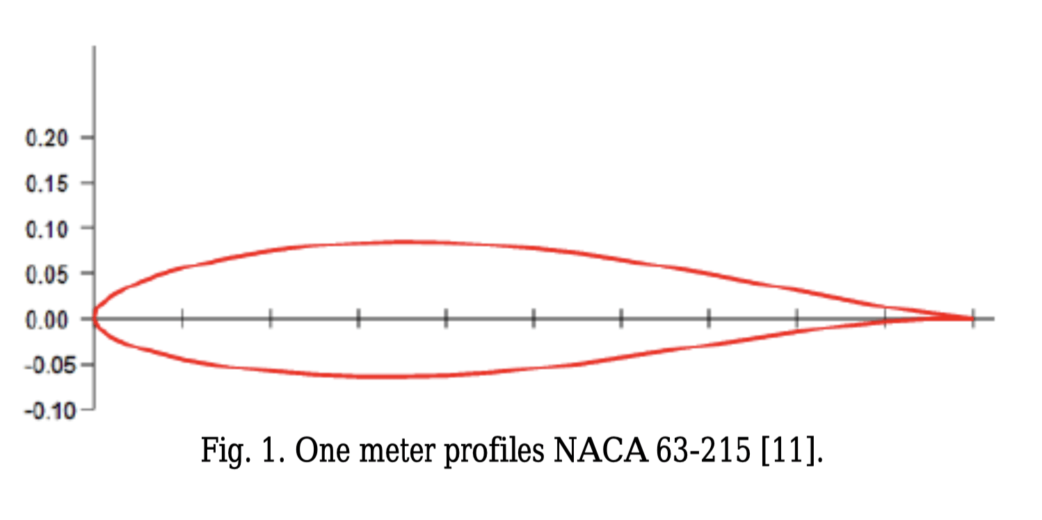
Then, an analytical optimization process can be run, to find the most efficient airfoil and attack angle. This can be used to increase the output torque by choosing an optimized wind airfoil as presented by M Mohammed. Out of many airfoils listed in Table 3, the most optimal was NACA 63-215 and having a blade length of 9 m. This airfoil was chosen due to its characteristics that make it suitable for low-speed wind turbine applications: it provides a high lift coefficient and maintains a favorable lift-to-drag ratio. Its geometric properties: maximum thickness of 15% and maximum camber of 1.1% at 50% chord, also meet the structural and aerodynamic requirements of these blades.
| Airfoil | Reason for Consideration | Reason Not Chosen / Limitation |
| NACA 63-218 | Balance between lift and drag; suitable for low-speed wind | Lift-to-drag ratio not optimal compared to NACA 63-215 |
| NACA 64-415 | Favorable aerodynamic characteristics for low-speed conditions | Performance not as optimized as NACA 63-215 |
| NACA 65-421 | Low drag and effective lift; tested for aerodynamic performance | Requires further testing for small-scale wind turbines |
| FX S 02/1-158 | Tested for wind turbine applications | Performance not as optimized as other airfoils |
| FX 60-126/1 | Considered for wind turbine blades | Performance may not be as favorable as other options |
| SG6043 | Used in wind turbine applications | Performance not as optimized as other airfoils |
| SG6040 | Used in wind turbine applications | Performance may not be as favorable as other options |
By using the NACA 63-215, we are able to maximize  , optimize the rotor radius and therefore increase , even in areas with low wind speeds4.
Pitch Control and Speed Regulation
PID Control and Intelligent Genetic Algorithms (IGA)
In SSWTs, the pitch angle of the blades can be monitored and regulated by many control devices. One of these control devices is Proportional-Integral-Derivative (PID) Control13.
PID controllers are located in the nacelle.They are supported by sensors and actuators which then monitor the rotor speed, generator output, and wind conditions. These controllers use a feedback control principle. After an error is passed by the system, the error between desired and measured outputs is fed back into the system to adjust blade pitch and maintain stable operation and constant power output13.
An important algorithm used to find errors is the Standard GA (genetic algorithm) which is used to solve optimization problems by evolving a population of candidate solutions toward an optimal solution3.
Another evolving algorithm is the IGA Intelligent Genetic Algorithm). The IGA allows a human to interact with the functions to evaluate solutions correctly. Humans act as evaluators and innovators after test runs of the algorithm. Engineers subjectively rank the performance under uncertainty, smoothness, robustness, etc. This allows experts to intuitively account for uncertainties and also make adjustments during testing, immediately after a simulation run. IGA is especially useful in situations with complex trade-offs and changing requirements because it incorporates human expertise, which guarantees a more comprehensive and flexible approach to tackling complex problems3.
In Civelek’s work, the PID parameters of the blade-pitch controller were optimized using an Intelligent Genetic Algorithm (IGA). The genetic algorithm generated sets of candidate PID gains, and human experts interacted with the optimization process by evaluating system responses (e.g., smoothness, robustness, and overshoot) after simulation runs. Their evaluations guided the evolutionary search toward more effective parameter sets14‘3.
Maximum Power Point Tracking (MPPT) with PMSGs
It is the process of controlling rotation speed of the rotor allowing for optimum power output.
A power tracking control called MPPT or maximum power point tracking is used to efficiently change rotation speeds using the PO method also known as the perturb and observe method. The working principle is to increase and decrease the voltage by adjusting the duty cycle on the power side converter, which simply means that it changes the output voltage through on and off cycles12.
The PO method perturbs the operating point and observes the resulting power change; near the maximum, this produces a small steady-state oscillation around the MPP. Oscillations are managed by using adaptive step sizes (larger steps far from the peak, smaller steps near it), optional deadbands or stop-perturb rules around the MPP, and filtered measurements/approaches shown to reduce ripple while maintaining tracking speed. The PO system works like this:
(1) To investigate the precise value of the current PMSG generator output voltage, the first voltage measurement is established.
(2) The current value of the power PMSG generator is measured.
(3) The power difference between the current and previous measurements are then computed.
(4) To determine the mechanism underlying the variations, the voltage and power are compared. The generator power and measured voltage differences will determine whether the generator voltage is higher or lower based on this comparison.
(5) Step 1 is repeated if the aforementioned steps prove successful12.
After using this in the PMSG (Permanent magnet synchronous generator) with and without the MPPT software, the results are that the MPPT software has an average power increase of 50.77%12.
Optimization in Low Wind Speed Conditions
There are a few ways in which we can optimize a small scale wind turbine for low wind speeds.
Airfoil- Finding the right airfoil for a given wind speed can be beneficial to collecting as much wind as possible during low speed conditions
Lightweight airfoil materials – Lightweight airfoil materials decrease the rotor’s moment of inertia, thus lowering the aerodynamic torque / wind speed needed to overcome losses. This reduces the cut in speed of the turbine.
Attack angles – the attack angles of the wind are also an important factor, which can also help in the choosing of the right airfoils
Longer blades – longer blades can help in the capturing of wind energy more efficiently than smaller blades
PMGs – Permanent magnet generators are very useful for low wind speed conditions and thus is a great choice while creating a wind turbine meant for low wind speeds. Abduh et al. (2025) conducted a few detailed analyses of PMGs under very low wind conditions. Cogging torque impedes startup performance, and can be effectively mitigated through design optimizations such as slot skewing and magnet pole arc adjustments.
Their experimental results confirm that PMGs can maintain efficiency at low speeds. Thus, they are an optimal choice for SSWTs1.

Discussion and Analysis
Recent Trends and Innovations in Small-Scale Wind Technology
The highest wind energy generating country is China with the installed capacity of 62,733 MW, with France, UK and USA trailing behind, with a growth rate of 88%. The most commonly used type of wind turbines are the HAWTS. But VAWTS are also gaining traction in the modern world. And according to the University of Michigan wind project installed costs declined by 71% from 4,804/kW in 1983 to 1,370/kW in 2022. In Europe, there are some coasts where offshore wind development began in the early 1990s, several installations are reaching the end of their 20- to 25-year lifespan. By the mid-2020s, many of these turbines will need to be either repowered, dismantled or replaced. Yet this was in the 90s. What is the expected lifespan of wind turbines nowadays? According to the department of energy, that number has gone up to about 30 years16‘17.
New concepts like the soft stall concept are used to stop loss of energy due to hysteresis.
Small wind turbines use soft stall control to control power output, permitting the blades to enter an aerodynamic stall rather than stopping suddenly. Without the need for moving components like furling mechanisms, this method allows the turbine to continue producing energy at higher wind speeds even while maintaining operation close to maximum at low to medium wind speeds. By operating at a lower tip-speed ratio during strong winds, soft-stall control also lessens the turbine’s mechanical stress, noise, and thrust loads. Compared to conventional furling control, this method enhances turbine performance, longevity, and overall energy capture efficiency18.
Many converters like the DCM (Discontinuous Conduction Mode) converters, CM (Continuous Mode) converters, FCM (Forced Continuous Mode) converters, etc, are used, which allow efficient transformation of DC and AC voltages. All these power electronics including different types of permanent magnets in the generators help in the generation of the most amount of energy6‘13.
Challenges in Design, Simulation, and Implementation
Modern wind turbines use hybrid structures to improve performance. The cost of these materials can be made at 1/10th of the cost of materials used to manufacture typical aerospace materials. Yet, as the weight of the turbine parts increase and turbines move farther offshore, the logistics and transportation become more expensive. Generators often use permanent magnets made with rare-earth elements, which are increasing demand across many industries and applications. Therefore, alternate ways are being investigated such as by developing superconducting generators or other alternatives including magnet reuse and recycling. In order to assess the economics of plant operation, an increasing number of merchant market power plants will need to have a better understanding of the present level of damage to wind turbine components as well as the anticipated rise in damage over the course of an operating period. Therefore, to establish a solid foundation for evaluating the increasing degradation in components, fundamental research as well as advances in inspection and structural health monitoring are required19.
Software issues:
Some issues arise when using softwares. Although they can capture the pertinent turbine and plant physics, simulations of the basic fluid–structure interaction are computationally expensive. Advanced softwares are not readily available for designing wind turbines, while simple algorithms can be more expensive and more cautious by nature, and safety factors are required to take operational, modeling, and physical uncertainties into account. AI and Machine Learning softwares can be used to create high fidelity data from fluid structure models for turbine and plant design19. However, data from analytical fields can come with many uncertainties which have to be quantified. The data required to validate complex models will come with a significant monetary investment and the data assimilation of these models also require a heavy computational stress too. The issue with testing out these designs in real life comes with their own costs, as wind turbine farms can be multi billion dollar projects nowadays, not to mention all the money which goes into verifying the data in high fidelity data methods. Yet, design limitations include additional needs related to production, logistics, operation, maintenance, disposal, recycling, and other areas outside aerodynamics, structures, and controls. Some of them being operation, maintenance, disposal, recycling, and so on19.
Sustainability, Economics, and Rural Applications
SSWTs contribute to distributed renewable energy generation, but their economic feasibility depends heavily on wind conditions. Jurasz et al. (2025) conducted a comprehensive analysis using six years of wind speed data from about 269 gauging stations in Poland to evaluate the energy potential and cost-effectiveness of SSWTs. The study realized that, under favorable wind conditions, the Levelized Cost of Electricity (LCOE) for SSWTs could be as low as €0.223/kWh. This would make them competitive with residential solar photovoltaics in certain locations. But, only a small fraction of sites (7.5%) achieved a capacity factor above 10%. Thus limiting the economic attractiveness of SSWTs in areas with relatively lower wind speeds. These findings emphasize the importance of site assessments, so we can ensure that SSWTs provide a cost-effective contribution to local energy systems20.
VAWTs are often considered for urban or small-scale residential settings and environments due to their ability to capture wind from seemingly all directions and their simpler installation requirements. An issue that arises here is noise generation, as it affects the acceptability of VAWTs in residential environments. Wang & Ferng (2024) developed a model to simulate VAWT noise and worked with several mitigation techniques, some being the use of deflectors, masks, and wall roughness. The study proved that deflectors were effective in reducing noise levels. Simulation accuracy was also essential for reliable predictions. These results suggest that aerodynamic design and attention to structural components can substantially reduce noise, thus making VAWTs more suitable for urban integration. Implementing these strategies allow designers and engineers to have community comfort, without compromising energy generation. Thus, solving a major problem related to urban adoption of SSWTs21.
SSWTs deployed in urban areas usually encounter challenges due to complex wind flows and turbulence. The presence of buildings and other structures tends to disrupt wind patterns, which leads to increased turbulence and unsteady wind conditions at lower altitudes. This turbulence can induce dynamic loading on turbine blades, effectively reducing their efficiency and potentially shortening their operational lifespan. Additionally, the interaction of wind with urban structures can create wind shadows and recirculation zones, further diminishing the available wind resource for energy generation. Consequently, SSWTs in urban environments often operate below their optimal performance levels, making their integration into the urban energy mix more challenging22.
| Technique / Concept | Type | Advantages | Disadvantages | Appropriate Applications |
| BEMT (Blade Element Momentum Theory) | Aerodynamic Modeling | Simple , widely used for rotor design | Assumes steady flow, less accurate for complex aerodynamics | Preliminary design and performance estimation of rotors |
| CFD (Computational Fluid Dynamics) | Aerodynamic Modeling | High accuracy. Can model complex flows,turbulence, etc. | Computationally expensive, requires expertise | Detailed aerodynamic analysis, performance prediction |
| ANSYS | CFD / Structural Analysis Software | Great simulation, integrates CFD & FEA | Expensive, steep learning curve | Aerodynamic and structural analysis of turbine components |
| MATLAB | Simulation & Modeling | widely used for control and system modeling | Requires coding knowledge, less visual for geometry | System simulation, control algorithm testing, small-scale modeling |
| PID (Proportional-Integral-Derivative Control) | Control | Simple, robust, widely applied | May not handle nonlinearities or large disturbances well | Speed regulation, power output control |
| GA (Genetic Algorithm) | Optimization | Global optimization, handles nonlinear problems | Computationally intensive, may converge slowly | Blade shape optimization, layout design, control tuning |
| IGA (Intelligent Genetic Algorithm) | Optimisation | Decreased uncertainty in accuracy due to human oversight | Time consuming and tedious | Optimizing blade design and turbine performance. |
| PPT (Power Point Tracking / MPPT) | Electrical Control | Maximizes energy extraction from wind | Adds system complexity, may need additional electronics | Small-scale wind systems with varying wind speeds |
| ML (Machine Learning) | Optimization / Prediction | Can predict complex patterns, adaptive | Requires data, risk of overfitting | Wind forecasting, adaptive control, performance optimization |
| PMSG (Permanent Magnet Synchronous Generator) | Electrical Generation | High efficiency, compact, low maintenance | Costly, sensitive to temperature | Small-scale wind turbine generators |
| PO (Perturb and Observe) | MPPT Control | Simple to implement, low computational cost | Oscillates near maximum power | Tracking Maximum Power in wind systems |
| MPPT (Maximum Power Point Tracking) | Electrical Control | Ensures optimal power output | Requires electronics and control logic | Off-grid and grid-tied small wind turbines |
| Autodesk Fusion 360 | CAD / Design Software | Easy 3D modeling, integrated simulation tools | Limited CFD capabilities, may need plugins | Turbine component design, prototyping |
| Betz and Glauert Theories | Aerodynamic Theory | Fundamental understanding of rotor efficiency | Idealized assumptions, ignores losses | Rotor efficiency estimation, theoretical analysis |
| Tip Loss Correction | Aerodynamic Theory | Improves accuracy of BEMT predictions | Empirical, not always precise | Blade design, correcting theoretical predictions |
| Airfoil | Aerodynamic Component | Determines lift and efficiency | Performance sensitive to conditions | Rotor blade design, aerodynamic performance |
| Airfoil Material | Structural Component | Impacts strength, weight, durability | Material limits may restrict performance | Blade manufacturing, structural design |
| Attack Angles | Aerodynamic Parameter | Critical for lift optimization | Incorrect angles cause stall and efficiency loss | Blade profile design, rotor control strategies |
Implications for Future Research
Unique Efficiency Problems Faced By SSWTs
SSWTs face their own set of efficiency challenges that hinder their large-scale adoption. Unlike their large counterparts, SSWTs operate in turbulent and variable wind conditions leading to less energy conversion efficiency. Thus performance prediction is difficult. The limited measurement resources and design constraints further complicate reliability assessments. Economic viability becomes another challenge. Manufacturing and maintenance and costs per unit of energy are higher than for larger turbines. Grid integration also presents issues, as the intermittent power output of SSWTs must be balanced within local energy systems. Moreover, acceptance in urban settings presents itself as challenges: noise, aesthetics, and space limitations in urban areas, can hinder adoption. The above hindering issues will require improvements in turbine design, control systems and economic models for SSWTs to be more widely used. Studies have presented the need for better predictive models, optimized rotor designs, and innovative strategies to improve the overall efficiency and adoption of small-scale wind technology23.
AI and Machine Learning Integration
AI has taken the world by storm with its capabilities of being able to learn and help solve problems efficiently. We can use AI in the wind generation aspect of the world. One way this could take place is by extracting data from Fluid structure models and help in predicting the variability of wind as well19.
Improved Wind Variability Models
Wind speed, direction, and turbulence vary significantly across time and location. Current models need improvement in capturing these variations more accurately, particularly for complex terrains and offshore environments19.
Urban Integration of Micro Wind Turbines
Most WTs are found far from urban settings, where average wind speed is higher due to no obstructions from buildings. It also may not complement the beauty of the city. But, if we develop more appealing wind turbines with noise reduction, it would definitely increase influx of energy and allow us to switch to no fossil fuels19.
Advancements in Energy Storage and Transmission
Energy from wind turbines is lost due to poor storage methods and transportation. However, in the coming years, there will be research into development of better storage facilities and transportation, especially for offshore wind turbines19.
Conclusion
Summary of Key Findings
In this paper we have discussed many optimization techniques as well as issues and thoughts about the future of the wind energy generation industry.
Theories of Blade Design
BEMT: Uses induction factors and tip speed ratio to optimize blade form.
Establish theoretical efficiency and thrust concerns in Betz and Glauert’s theories.
Multidisciplinary optimization strikes a balance between structural, economic, and aerodynamic considerations.
Pitch Control uses PID controllers to modify blade angles for maximum power.
Algorithms like GA and IGA: Enhance pitch control through human experience and optimization.
In PMSG systems, the Turbine Rotation Speed MPPT with PO Method dynamically modifies speed to achieve a 50.77% power boost.
Trends and Difficulties
Improvements include more durable turbines, lower prices, effective power converters, and hybrid materials.
Difficulties include offshore logistics, expensive simulations, and material dependence.
AI for Optimization Research in the Future: Improve efficiency and forecast wind fluctuations.
Urban Integration: Create more aesthetically pleasing, silent turbines for urban areas.
Transport & Storage: Enhance the handling of offshore energy.
Contributions to the Field
Progress in the Study of Small Scale Wind Turbines
Innovative Blade Design: Research on increasing the efficiency of wind turbines is directly aided by theories like Blade Element Momentum Theory (BEMT) and airfoil selection, which increase energy capture efficiency.
Optimizing Algorithms: The application of Intelligent Genetic Algorithms (IGA) and Genetic Algorithms (GA) to optimize pitch control demonstrates the possibility of more intelligent, flexible systems in renewable energy technologies.
Innovations in Materials: The advancement of renewable energy systems depends on addressing issues with resource sustainability and turbine longevity through the investigation of lightweight, robust, and recyclable materials.
AI Integration: Using AI and machine learning for urban wind modeling, optimization, and predictive maintenance is in line with the most recent developments in renewable energy research.
Future Recommendations
Future research in wind turbine creation should focus on integrating AI and ML in optimization, improving wind variability models, and integrating them in urban settings. AI can help predict wind variability by extracting data from fluid structure models. Improving wind turbine efficiency close to the Betz limit will always be a challenge. Improving wind variability models, particularly in complex terrains and offshore environments, could help reduce energy loss and transition to renewable energy sources. Research will and should also focus on improving energy storage and transportation methods for offshore wind turbines.
Glossary
TSR – Tip Speed Ratio
CFD – Computational Fluid Dynamics
PMSG – Permanent Magnet Synchronous Generator
BEMT – Blade Element Momentum Theory
MPPT – Maximum Power Point Tracking
DCM – Discontinuous Conduction Mode converter
CM – Continuous Mode converter
FCM – Forced Continuous Mode converter
Acknowledgements
I would like to thank my science research mentor(s), my school faculty, and the authors of the cited studies for providing foundational insights into this topic. Special thanks to the developers of MATLAB, ANSYS, and Autodesk Fusion 360, whose tools were invaluable in simulation analysis.
References
- S. Abduh, S. Karunanithi, T. Nur. Analysis of the cogging torque reduction in permanent magnet generators for a very low wind speed. Energies. Vol. 18, pg. 2802, 2025, DOI: 10.3390/en18112802, https://www.mdpi.com/1996-1073/18/11/2802 [↩] [↩]
- H. Cao, Aerodynamics analysis of small horizontal axis wind turbine blades by using 2D and 3D CFD modelling(Master’s thesis, Univ. Central Lancashire, UK, 2011). [↩]
- Z. Civelek. Proportional–integral–derivative parameter optimisation of blade pitch controller in wind turbines by a new intelligent genetic algorithm. IET Renewable Power Generation. Vol. 10, pg. 806–814, 2016, https://ietresearch.onlinelibrary.wiley.com/doi/10.1049/iet-rpg.2016.0029 [↩] [↩] [↩] [↩]
- M. Mohammadi, A. Mohammadi, M. (Moona) Mohammadi, H. Neisi. Optimization of small scale wind turbine blades for low speed conditions. Journal of Clean Energy Technologies. Vol. 4, pg. 140–143, 2016, DOI: 10.7763/jocet.2016.v4.268, https://www.researchgate.net/publication/281788567_Optimization_of_Small_Scale_Wind_Turbine_Blades_for_Low_Speed_Conditions [↩] [↩] [↩] [↩] [↩] [↩] [↩] [↩] [↩]
- O. O. Awopetu, T. J. Erinle. Development of a small-scale wind turbine. AU Journal of Technology. Vol. 17, pg. 73–80, 2013, https://www.academia.edu/35620047/Development_of_a_Small_Scale_Wind_Turbine [↩] [↩] [↩] [↩]
- R. Carriveau. Small scale wind turbines. In: N. Mahdavi Tabatabaei, H. Agoh, editors. Power Electronics in Renewable Energy Systems and Smart Grid Integration. Cham: Springer; 2019. p. 305–331, https://www.intechopen.com/chapters/39956 [↩] [↩]
- M. A. Al-Rawajfeh, M. R. Gomaa. Comparison between horizontal and vertical axis wind turbine. International Journal of Applied Power Engineering. Vol. 12, pg. 13–23, 2023, https://ijape.iaescore.com/index.php/IJAPE/article/view/20519 [↩]
- A. Tummala, R. K. Velamati, D. K. Sinha, V. Indraja, et al. A review on small scale wind turbines. Renewable and Sustainable Energy Reviews. Vol. 56, pg. 1351–1371, 2016, DOI: 10.1016/j.rser.2015.11.068, https://www.researchgate.net/publication/288918068_A_review_on_small_scale_wind_turbines [↩]
- H. Cao. Aerodynamics analysis of small horizontal axis wind turbine blades by using 2D and 3D CFD modelling. Master’s thesis. Preston (UK): University of Central Lancashire; 2011, https://clok.uclan.ac.uk/id/eprint/2399/1/CaoH_final_thesis.pdf [↩] [↩] [↩]
- T. Burton, D. Sharpe, N. Jenkins, E. Bossanyi. Wind energy handbook. 2nd ed. Chichester: John Wiley & Sons; 2011, https://www.researchgate.net/publication/281688000_Wind_Energy_Handbook_Second_Edition [↩]
- A. Betz. Das Maximum der theoretisch möglichen Ausnutzung des Windes durch Windmotoren. Zeitschrift für das gesamte Turbinenwesen. Vol. 26, pg. 307–309, 1920,https://www.researchgate.net/publication/236951297_The_Maximum_of_the_Theoretically_Possible_Exploitation_of_Wind_by_Means_of_a_Wind_Motor [↩]
- R. Syahputra, I. Soesanti, Performance Improvement for Small-Scale Wind Turbine System Based on Maximum Power Point Tracking Control. Energies 12(20), 3938 (2019). [↩] [↩] [↩] [↩]
- M. R. Patel. Wind and solar power systems: design, analysis, and operation. 3rd ed. Boca Raton (FL): CRC Press; 2021, https://diamoitruong.com/wp-content/uploads/2018/11/6-wind-and-solar-power-system-analysis.pdf [↩] [↩] [↩]
- S. Baburajan. Pitch control of wind turbine through PID, fuzzy, and adaptive fuzzy-PID controllers. Master’s thesis. Rochester (NY): Rochester Institute of Technology; 2017, https://repository.rit.edu/cgi/viewcontent.cgi?article=10779&context=theses [↩]
- M. Arifujjaman, M. T. Iqbal, J. E. Quaicoe. Efficiency comparison of two possible grid connected small wind turbine systems. In: Proceedings of the 2010 IEEE Energy Conversion Congress and Exposition (ECCE/ECCE-Canada). Halifax, Nova Scotia, Canada. Aug 25–27, 2010. p. 1–8, https://www.researchgate.net/publication/323129255_Efficiency_comparison_of_two_possible_grid_connected_small_wind_turbine_systems [↩]
- Retgen. Wind turbine prices. Retgen; [date unknown], https://retgen.com/en/wind-turbine-prices/ [↩]
- R. Syahputra. Performance tracking of maximum power output. Energies. Vol. 12, pg. 3938, 2019, DOI: 10.3390/en12203938, https://www.mdpi.com/1996-1073/12/20/3938 [↩]
- E. Muljadi. Soft-stall control versus furling control for small wind turbine power regulation. Golden (CO): National Renewable Energy Laboratory (NREL); 1998, https://docs.nrel.gov/docs/legosti/old/25100.pdf [↩]
- P. Veers, K. Dykes, D. Laird, et al. Grand challenges in the design, manufacture, and operation of future wind turbine systems. Wind Energy Science. Vol. 8, pg. 1071–1131, 2023, DOI: 10.5194/wes-8-1071-2023, https://wes.copernicus.org/articles/8/1071/2023/wes-8-1071-2023.pdf [↩] [↩] [↩] [↩] [↩] [↩] [↩]
- J. Jurasz, B. Bochenek, J. Wieczorek, A. Jaczewski, A. Kies. Energy potential and economic viability of small-scale wind turbines. Energy. Vol. 322, pg. 1250–1262, 2025, DOI: 10.1016/j.energy.2025.1250xx, https://www.researchgate.net/publication/389830310_Energy_Potential_and_Economic_Viability_of_Small-Scale_Wind_Turbines [↩]
- W. Y. Wang, Y.-M. Ferng. Numerical model for noise reduction of small vertical-axis wind turbines. Wind Energy Science. Vol. 9, pg. 651–664, 2024, DOI: 10.5194/wes-9-651-2024, https://wes.copernicus.org/articles/9/651/2024/wes-9-651-2024.pdf?utm_source=chatgpt.com [↩]
- K. C. Anup. Urban wind conditions and small wind turbines in the built environment. Renewable and Sustainable Energy Reviews. Vol. 101, pg. 240–251, 2019, DOI: 10.1016/j.rser.2018.11.034, https://www.sciencedirect.com/science/article/abs/pii/S0960148118308474?utm_source=chatgpt.com [↩]
- A. Bianchini, G. Bangga, I. Baring-Gould, A. Croce, J. I. Cruz, R. Damiani, et al. Current status and grand challenges for small wind turbine technology. Wind Energy Science. Vol. 7, pg. 2003–2037, 2022, DOI: 10.5194/wes-7-2003-2022, https://www.researchgate.net/publication/363008838_Current_status_and_grand_challenges_for_small_wind_turbine_technology [↩]


