
Abstract
Background/Objective: Portable telescopic ramps give wheelchair users access to steps and thresholds where a permanent ramp cannot be built. Their nested sections connect only through sliding overlaps, yet ramp research concentrates on slope and telescopic-structure research on crane booms. The overlap length of an accessibility ramp has not been examined as a structural design variable. This study asked at what overlap length the mid-span deflection of a portable telescopic ramp exceeds the serviceability limit, and how the number of telescoping sections changes that threshold.
Methods: A 1.228 m aluminium 6061-T6 ramp rail carrying a 699 N mid-span load was modelled with Euler-Bernoulli beam elements assembled by the direct stiffness method in Python. Each overlap was represented as a rotational spring whose stiffness follows a force-couple model, kᵣ = ½ kᴄ Lₒᵥ². The model reproduced the closed-form beam solution with 0.0000% error, and overlap was then swept from 2 mm to 150 mm across two-, three-, and four-section layouts, 320 cases.
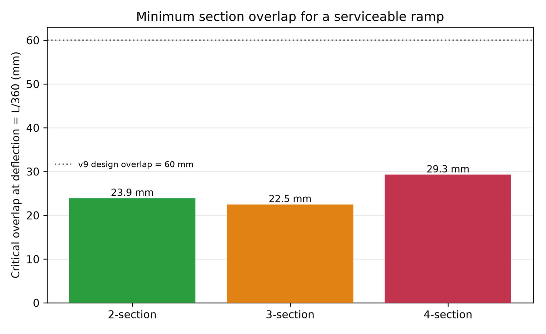
Results: At a 2 mm overlap the mid-span deflection reached 240 mm to 360 mm, against 1.74 mm for a continuous beam. The critical overlaps at the L/360 limit of 3.41 mm were 23.9 mm (two-section), 22.5 mm (three-section), and 29.3 mm (four-section). Maximum bending stress stayed at 14.3 MPa in every case, a safety factor of 16.8.
Conclusions: Serviceability, not strength, governs telescopic ramp design; joint position matters as much as joint count; and the 60 mm design overlap of the reference ramp carries roughly a two-fold margin.
Keywords: telescopic ramp, wheelchair accessibility, section overlap, semi-rigid connection, Euler-Bernoulli beam, direct stiffness method, serviceability limit
Introduction
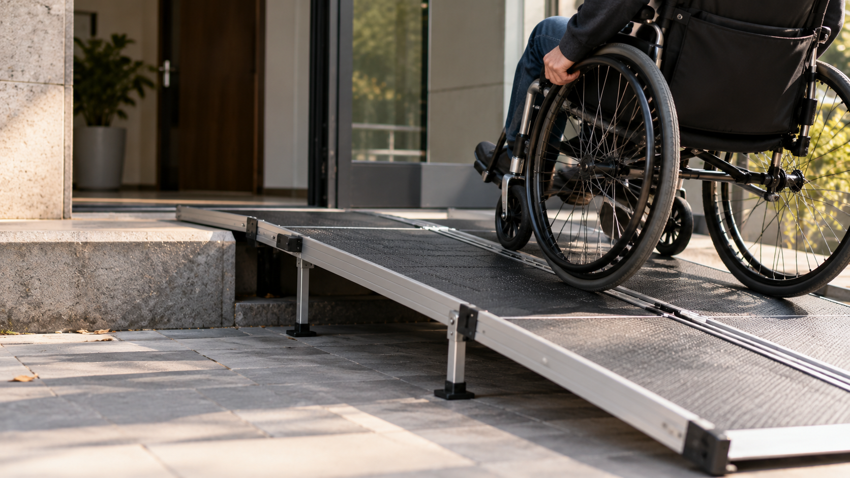
A wheelchair user faces a step the way a car faces a wall. Ramps remove that wall, and accessibility codes therefore regulate them closely: Indian standard IS 7480 fixes slope, width, and edge protection for ramps serving disabled persons1, and the national harmonised guidelines carry the same requirements into public buildings2. Research attention has followed the codes. Studies of ramp usability concentrate on slope, the variable the codes regulate, and have measured how steeper ramps raise the effort and risk of wheelchair ascent3. A permanent ramp, however, cannot be built at every doorway. Portable ramps fill the gap, and among them the telescopic ramp is the most compact: several nested sections slide together for storage and pull apart for use.
A telescopic ramp is not a rigid beam. Where two sections meet, the outer section, with the larger cross-section, hugs the inner section over an engagement length called the overlap. When a load steps on the ramp, the ramp sags, and that sag is called deflection. How much it sags depends on how well each overlap carries bending from one section into the next. A long overlap makes the ramp behave like one continuous beam. A short overlap lets the sections pivot almost independently, like a loose door hinge, and the ramp folds into a sharp V at the joint.
Structural engineering has a name for a joint that carries some but not all of the bending moment: a semi-rigid connection. A large body of work models such connections in steel frames as rotational springs, beginning with polynomial moment-rotation fits4 and continuing through databases and three-parameter models of connection behaviour5,6. Classification systems place every joint on a scale from pinned to rigid by its rotational stiffness7, and Eurocode 3 formalises that scale in design practice8. Frame analyses show that ignoring the semi-rigid behaviour of real joints misestimates deflections9. On the telescopic side, the published work concentrates on hydraulic crane booms, where the contact stresses between nested segments10 and the strength of telescopic jibs11 have been studied with detailed finite element models, and more recent work continues in the same vein, analysing the instability load of a telescopic crane boom built from co-rotational nested beam elements12. Portable wheelchair ramps themselves have drawn separate, practical attention that stops short of this question: a comparative evaluation of twelve commercial portable ramps catalogued their design features and performance without analysing an internal joint13, and a recent finite element stress simulation of a wheelchair ramp modelled it as a single continuous structure rather than a telescoping assembly14. Between these two literatures sits an open question. The overlap of a telescopic accessibility ramp is mechanically a semi-rigid connection, but no published study treats its length as the design variable and asks how short it may become before the ramp stops being usable.
The question matters because overlap length is the real design knob of a telescopic ramp. A hinge maker can quote a rotational stiffness for a hinge, but a telescopic ramp has no hinge; the stiffness of each joint is determined by the length of overlap. A manufacturer can read an overlap length off a drawing, understand it, and execute it immediately. A minimum overlap is therefore a specification a designer can actually enforce, in a way that an abstract joint stiffness is not.
This study asked two specific questions. First, at what overlap length does the mid-span deflection of a portable telescopic ramp under its rated load exceed the L/360 serviceability limit? Second, does adding more telescoping sections always raise that critical overlap? The working hypothesis was that more sections always means worse performance, since each extra joint adds rotational give.
The scope is deliberately narrow. One independent variable, the section overlap length, is swept while material, cross-section, span, and load stay fixed. The model is linear-elastic beam theory with a static load held at mid-span, the worst case for deflection because the middle is the furthest point from both supports at once in a continuous beam; for a beam with discrete semi-rigid joints this is not automatic, since a load near a soft joint could in principle rotate that joint harder than a mid-span load does, and a dedicated load-position sweep reported in Results confirms mid-span remains the governing position across the range in which this paper’s thresholds are read. Contact friction, local wall crushing, and plate effects are excluded by design, so that any change in the answer can be traced to the overlap alone.
The theoretical framework is classical. The ramp rail is an Euler-Bernoulli beam15, each overlap is a rotational spring in the semi-rigid tradition16, and the spring stiffness follows from a force-couple model of the two bearing contacts at the ends of the engagement length. The beam is solved by the direct stiffness method, the model is first verified against the closed-form solution, and the overlap is then swept across four ramp layouts. The sections that follow give the full method, the results of the 320-case sweep, and the design implications.
Methods
Research design
This is a parametric computational study built on a verify-then-sweep design: the numerical model must first reproduce a known closed-form answer before any of its parametric output is trusted, following standard verification practice in computational mechanics1718. All code was written from scratch in Python 3 using NumPy 1.26 for matrix assembly and solution19, pandas 2.1 for the results table, and Matplotlib 3.8 for figures20. No commercial finite element package was used, so every stiffness term in the model is inspectable; the code and the full 320-case results table are available from the corresponding author upon reasonable request.
Geometry, material, and load
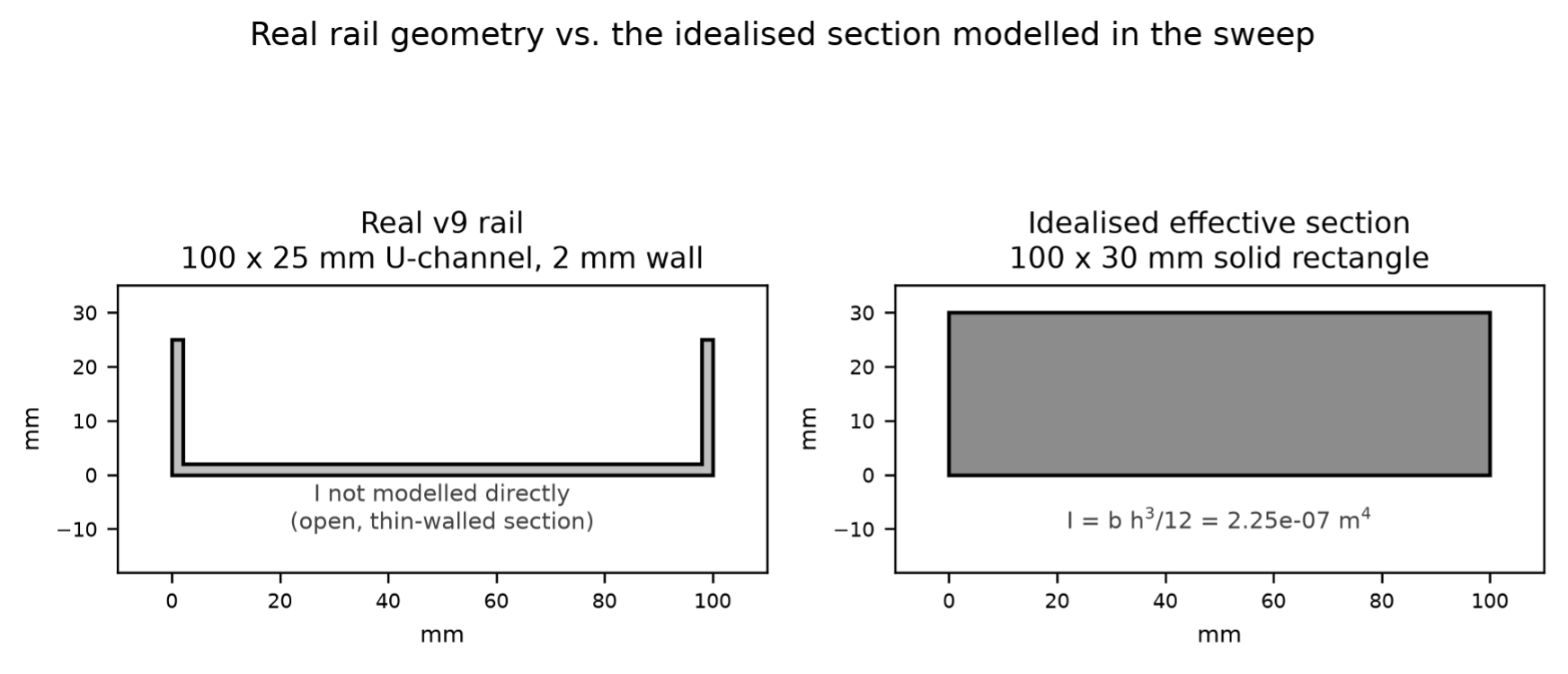
The geometry comes from the author’s RampUp v9 concept design, an unpublished personal design study by the author, not a commercial or third-party product, for a portable telescopic wheelchair ramp: two parallel rails, each built from four nested aluminium U-channel sections, extending to L = 1.228 m, rated for a 95 kg user, with a designed section overlap of 60 mm. The material is aluminium alloy 6061-T6, from the 6xxx family widely used for light transport structures21, whose extruded structural members are reviewed at length elsewhere22, with Young’s modulus E = 69 GPa and yield stress 240 MPa. The rated load is 95 kg times g = 9.81 m/s², multiplied by a 1.5 dynamic factor to cover bouncing and uneven wheel loading — a round-number engineering margin, since no code specifies a dynamic factor for hand-portable ramps; it is broadly consistent with dynamic amplification factors of roughly 0.2 to 0.5 measured on other human- and vehicle-loaded structures23 and sits within the impact-and-fatigue testing philosophy of ISO 7176-8 for wheelchairs24, though neither source specifies this exact load case and a direct code basis for 1.5 does not exist, and divided across the two rails, giving P = 699 N per rail, applied as a point load at mid-span. Each rail is modelled over the full span as an effective solid rectangular section 100 mm wide and 30 mm deep. The second moment of area of a rectangle is I = bh³/12, which gives I = 2.25 × 10⁻⁷ m⁴; depth enters cubed, so the depth does most of the work in resisting bending — precisely, both deflection and bending stress scale with 1/I, and because I ∝ h³ for a rectangular section, depth is the dominant geometric parameter for both. The real v9 rail is a thinner 100 mm by 25 mm channel that stays stiff in service only because its free spans between overlaps are short (Figure 6 draws the two sections to the same scale). The effective 30 mm depth was fixed once, before the sweep, so that the rigid baseline satisfies the serviceability limit and the overlap remains the only variable under test. This is a deliberate modelling choice, not a measurement of the real channel: every deflection and critical-overlap number in this paper is therefore a property of this idealised surrogate section, not of the physical 100 x 25 mm channel, whose true second moment of area (open, thin-walled, and in the real part perforated) was not computed. ‘Connection to the design’ in the Discussion is reframed accordingly.
Beam theory and limits
The rail is treated as a simply supported Euler-Bernoulli beam, resting on the ground at one end and the step at the other, governed by EI d⁴w/dx⁴ = q(x)15. For a continuous beam with a central point load the closed-form mid-span deflection is δ = PL³/(48EI), which evaluates to 1.737 mm for the parameters above; this is the deflection of a perfectly rigid ramp, the best case that every telescopic layout is measured against. Two failure checks are applied. Strength is checked through the maximum bending stress σ = M(h/2)/I against a target safety factor of 3, meaning the stress anywhere in the ramp must stay below one third of the material’s capability, a threefold buffer for unexpected load such as extra weight or sudden impacts. Serviceability is checked against the standard deflection limit of span over 36025, which for this span is L/360 = 3.41 mm. L/360 is a general structural criterion, historically set to protect rigid finishes such as plaster ceilings from cracking under floor beams. Neither IS 74801 nor the harmonised accessibility guidelines2 specify a deflection limit for ramps, and no study located for this paper derives a deflection or slope-change threshold from wheelchair rollability directly, though rolling resistance on different surface types has been measured for wheelchairs elsewhere26. L/360 is used here as the closest available general-purpose serviceability benchmark27; Limitations returns to this gap.
The overlap joint model
Three kinds of joint bracket the possibilities. A rigid joint makes the two sections and the joint work together against the load as one piece. A pinned joint is like a door hinge: it holds the sections together but lets them rotate freely, so no bending moment crosses it. The overlap of a telescopic ramp is the third kind, a semi-rigid joint that carries some but not all of the moment8. The overlap acts as a rotational spring: when the inner section tilts, its left edge presses down into the outer wall and its right edge presses up into the opposite wall, and the outer section answers with a restoring torque that locks the mechanism in place. The two bearing contacts sit a lever arm Lₒᵥ apart, so a transmitted moment M is reacted by a force couple across the engagement length. With a bearing stiffness kᴄ at each contact, the equivalent rotational stiffness of the joint is kᵣ = ½ kᴄ Lₒᵥ². The square law is the core physics: doubling the overlap multiplies the joint stiffness by four, because the lever arm and the displacement-to-rotation conversion each grow with Lₒᵥ. A long overlap therefore behaves as if welded, while a short one does not, because there is not enough lever arm to create the couple needed to tie the two sections together. The bearing stiffness was assumed as kᴄ = Et = 1.38 × 10⁸ N/m, the local stiffness scale of the t = 2 mm aluminium wall; this choice is stated openly as the one assumed constant in the model. This is a first-order stiffness scale, not a mechanical derivation of the bearing behaviour of two nested channel walls: E·t has the dimensions of a translational stiffness (N/m), but it is not obtained from a contact-mechanics analysis of the joint or from a test, in the way the semi-rigid connection literature cited above builds its moment-rotation models from experimental data5. kᴄ is also treated as a lumped bearing stiffness for the full 100 mm rail width, independent of that width — it is not a per-unit-width value that would need multiplying by b before entering kᵣ = ½kᴄLₒᵥ². A wider or narrower rail would in reality change the contact area and hence kᴄ, an effect this single-constant model does not capture. ‘Sensitivity to the bearing-stiffness assumption’ in the Discussion quantifies how far the design conclusion moves if kᴄ is wrong by a factor of two in either direction.
Numerical method
Because of the overlapping joints, the closed-form deflection formula no longer applies, so the beam is broken into small pieces called elements, each with two nodes. Each node can displace and rotate, two degrees of freedom, so each element carries four degrees of freedom and its stiffness matrix is the standard symmetric 4 × 4 Euler-Bernoulli element matrix1528, assembled by the direct stiffness method. Roughly 120 elements span the ramp (each about L/120 long, with extra nodes inserted at every joint and load position). A mesh-convergence check comparing 40, 80, 120 (the density used throughout this paper), 160, 240, and 480 elements across the same span found the reported deflection and stress unchanged to six decimal places at every density tested, so the mesh is well converged and not the limiting factor in any reported result. At each overlap joint the mesh uses a split rotation: the two sides share one vertical displacement but keep separate rotations, and the rotational spring kᵣ couples the two rotations, following the established treatment of beams with internal rotational discontinuities29,30. The global stiffness matrix is assembled element by element, the simple supports impose zero displacement at both ends, and the system K u = F is solved directly. Mid-span deflection, the bending moment diagram, the maximum stress, and the safety factor are extracted from the solution.
Verification procedure
Verification means running the code for an answer already known from theory: if the code returns the same answer, the machinery contains no error. This is verification in the sense of Oberkampf and Trucano17: comparison against a closed-form mathematical solution, testing whether the code solves the assumed equations correctly. It is not validation, which would require comparison against a physical measurement; no such comparison was performed, and Future Work returns to this point. Three checks were required to pass with less than 1% error before the sweep. First, the rigid baseline with no joints must reproduce δ = PL³/(48EI) and M = PL/4. Second, a beam with one overlap joint at mid-span given a near-rigid spring of kᵣ = 10¹² N·m/rad must reproduce the same continuous-beam answers, which tests the joint machinery itself, not just the plain beam. Third, because the first two checks bracket the joint stiffness at zero and near-infinity while every swept case and both critical-overlap crossings fall in the intermediate band of roughly 10² to 10⁶ N·m/rad, a beam with one overlap joint at mid-span given a representative intermediate stiffness (kᵣ = 2.5 × 10⁵ N·m/rad, the value at the 60 mm design overlap) was checked against a closed-form solution obtained independently by the unit-load (Maxwell-Betti) method rather than against another run of the same code. Because the beam is statically determinate, the moment at the spring is always PL/4 regardless of kᵣ, so the relative rotation across the spring is (PL/4)/kᵣ, and by the unit-load theorem this adds an extra mid-span deflection of PL²/(16kᵣ) on top of the continuous-beam term: δ(kᵣ) = PL³/(48EI) + PL²/(16kᵣ). A deliberate-error test was also run: one support was removed on purpose to confirm the model detects an unstable structure rather than returning a plausible wrong number.
Parametric sweep and analysis
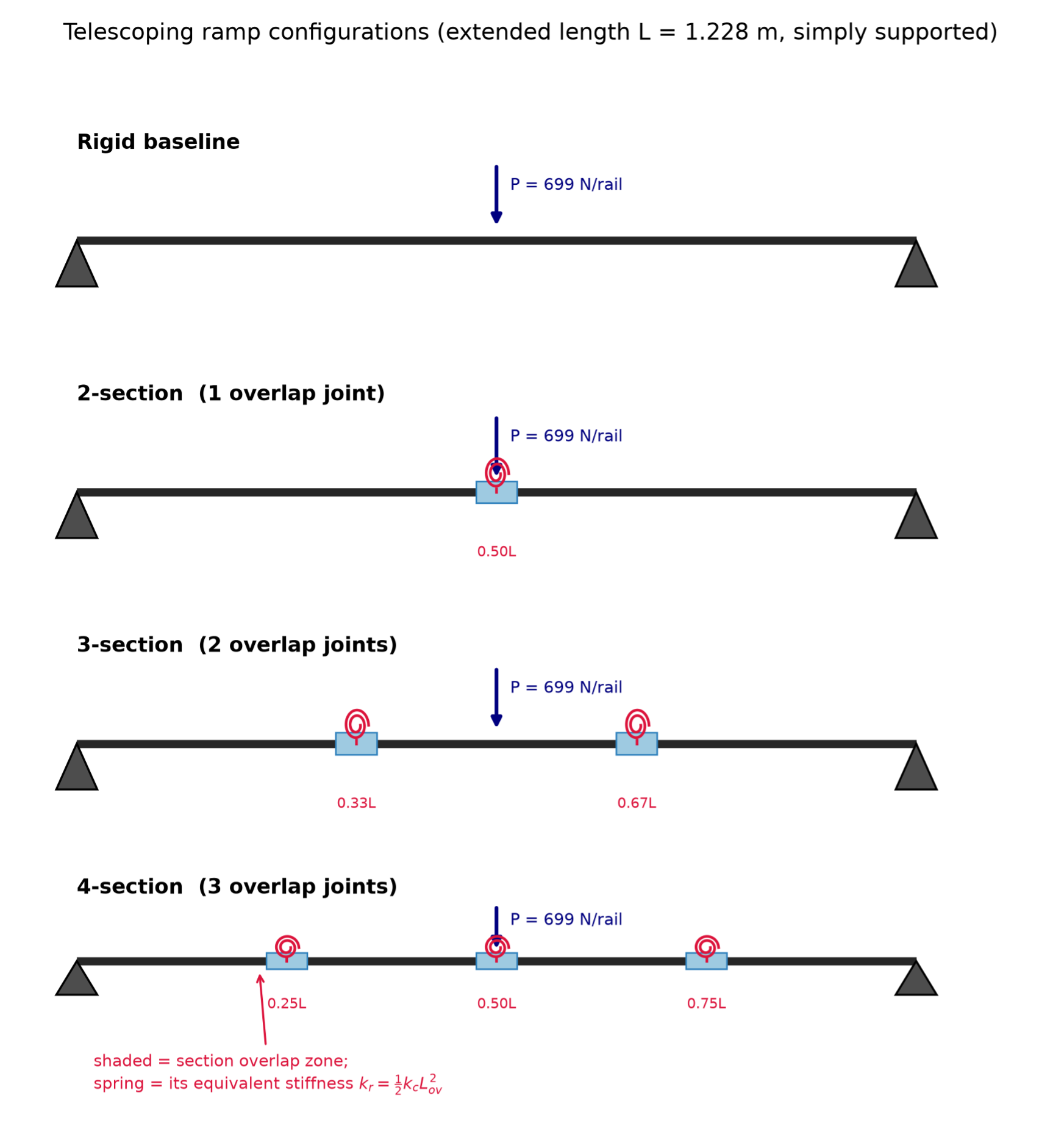
A parametric sweep keeps everything constant and varies one input to see how it alone affects the outcome. The overlap length was swept over 80 linearly spaced values from 2 mm to 150 mm, spanning from nearly disengaged to well past the designed 60 mm, across four layouts: a rigid baseline with no joints; a two-section ramp with one joint at 0.50L; a three-section ramp with joints at 0.333L and 0.667L; and a four-section ramp with joints at 0.25L, 0.50L, and 0.75L, the layout of the real v9 design. This gives 320 cases. For each layout the critical overlap, the overlap at which mid-span deflection equals exactly 3.41 mm, was found by linear interpolation between adjacent sweep points. All 320 cases are recorded in a results table with the configuration, overlap, joint stiffness, mid-span deflection, maximum stress, and safety factor.
Ethical considerations
The study is entirely computational. No human or animal subjects were involved, and all input data come from the author’s own design documentation and published material properties.
Results
Verification
The finite element model reproduced the closed-form solution exactly. The rigid baseline returned a mid-span deflection of 1.7370 mm against the closed-form 1.7370 mm and a maximum moment of 214.593 N·m against PL/4 = 214.593 N·m, an error of 0.0000% (agreement to double-precision floating-point machine epsilon, not literal mathematical exactness) on both quantities. The single-joint check with a near-rigid spring returned the same values, again with 0.0000% error, confirming that the split-rotation joint machinery reproduces the expected closed-form limit, not only the plain beam. A third check, at a representative intermediate stiffness of kᵣ = 2.5 × 10⁵ N·m/rad — the value at the 60 mm design overlap, well inside the 10² to 10⁶ N·m/rad band every swept case and both critical-overlap crossings occupy — was compared against the independent closed-form solution derived in Methods (δ = PL³/48EI + PL²/16kᵣ = 2.00222 mm); the FEM returned 2.00222 mm, again a 0.0000% difference. Five further spot checks spanning kᵣ = 3 × 10² to 10⁶ N·m/rad agreed to within 0.00002% in every case, closing the gap the first two checks left at zero and near-infinite stiffness. The agreement is exact to machine precision because Euler-Bernoulli elements are exact for point loads applied at nodes. These checks are verification in the sense of Oberkampf and Trucano17: they show the code solves the assumed equations correctly. They are not validation — none compares the model against a physical measurement of an actual overlap joint, and none is offered as one. In the deliberate-error test, removing one support made the stiffness matrix singular: without the right-hand support the structure is free to pivot downward about the remaining support under any applied load, which the solver reports as an unbounded deflection. A slight boundary-condition slip therefore cannot pass unnoticed.
Deflected shape
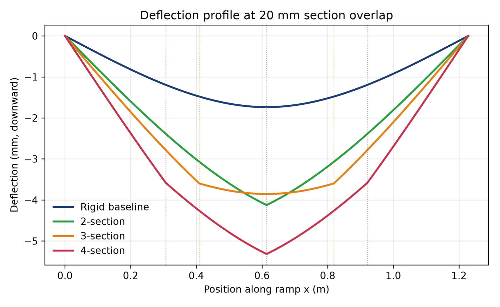
Figure 1 shows the four layouts and the position of each overlap joint. Figure 2 shows the deflected shape of each layout at a 20 mm overlap. The rigid baseline bends in a single smooth curve with its maximum of 1.74 mm at mid-span. The jointed layouts do not: at each overlap joint the slope changes sharply, and instead of a smooth curve the two-section ramp forms a sharp V shape right at the middle joint. This V shape is a kink, the visible signature of a joint too soft to carry the bending moment across. At this overlap the two-section ramp deflects 3.96 mm, the three-section ramp 3.71 mm, and the four-section ramp 5.07 mm, all past the 3.41 mm limit.
Deflection versus overlap
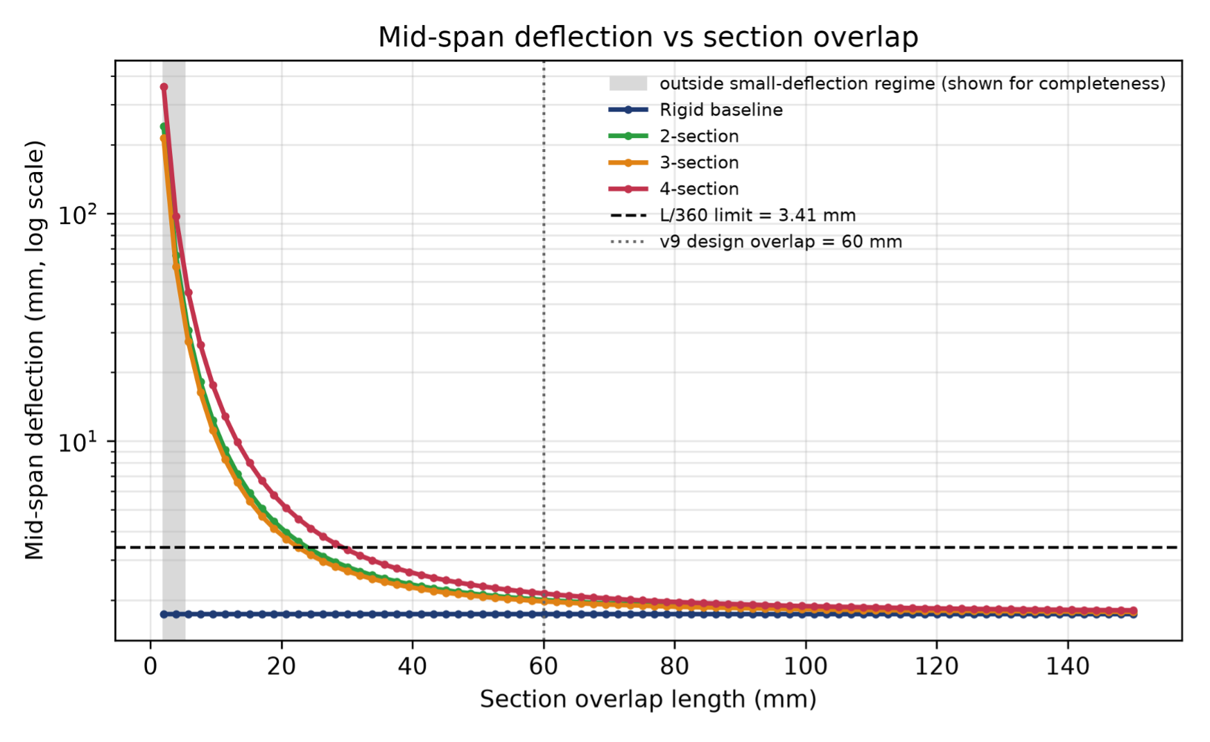
Figure 3 shows mid-span deflection against overlap length for all four layouts. At the shortest overlap of 2 mm the joint stiffness is 276 N·m/rad and the deflections are 240.4 mm for the two-section, 213.5 mm for the three-section, and 359.8 mm for the four-section layout, between 120 and 210 times the rigid value of 1.737 mm. Deflection falls steeply as the overlap grows, following the square-law rise of joint stiffness; at the designed 60 mm overlap, where kᵣ = 2.5 × 10⁵ N·m/rad, the three layouts deflect 1.97 mm, 2.00 mm, and 2.13 mm respectively. All four curves ultimately intersect and meet when the overlap is long enough, around the 120 mm mark, and at 150 mm every layout lies within 4% of the rigid baseline. Deflections at the low-overlap end of this range are large enough — 20 to 30% of the 1.228 m span — that linear Euler-Bernoulli theory’s small-deflection assumption (curvature approximated as w”, reliable while the maximum beam slope stays under roughly 0.10 rad) no longer holds; that assumption fails below about 4 to 6 mm of overlap for the three jointed layouts (Table 1). The corresponding portion of the sweep, shaded in Figure 3, is numerically well-behaved but not a physically meaningful prediction: it also fails a first-order local bearing-stress check below about 4.5 mm of overlap (see ‘Local bearing stress at the overlap contacts’ below), so no design conclusion in this paper relies on it. All three reported critical overlaps (22.5 to 29.3 mm) sit four to six times past the small-deflection threshold, deep inside the regime where the theory is reliable.
Critical overlap
The overlap at which each curve crosses the L/360 line of 3.41 mm is the critical overlap, shown per layout in Figure 5. The three-section ramp requires a minimum overlap of 22.5 mm, the two-section ramp 23.9 mm, and the four-section ramp 29.3 mm. The three-section layout, with two joints, needs a shorter overlap than the two-section layout, with one joint. The four-section layout needs the largest overlap of the three. All three critical overlaps lie below the 60 mm overlap specified in the v9 design, which is 2.0 times the largest of them.
Load position
Because the fixed mid-span load is justified above only by the continuous-beam argument, its validity for the jointed layouts was tested directly: for every layout, the load position was swept across the full span at overlaps of 5, 8, 12, 16, 20, and 60 mm, and the largest deflection anywhere along the beam (not only under the load) was recorded at each position. For the two- and four-section layouts, which place a joint exactly at 0.50L, mid-span remained the worst load position at every overlap tested, with zero gap to the next position tried. For the three-section layout, whose joints sit at 0.333L and 0.667L, loading near a joint produced a marginally larger peak deflection elsewhere on the span at very short overlaps — 8.6% higher at 5 mm, 3.4% higher at 12 mm — but this gap closed to zero by 16 mm, comfortably below the 22.5 mm critical overlap reported for that layout. The mid-span assumption therefore holds across the whole range in which this paper’s thresholds are read.
Stress and safety factor
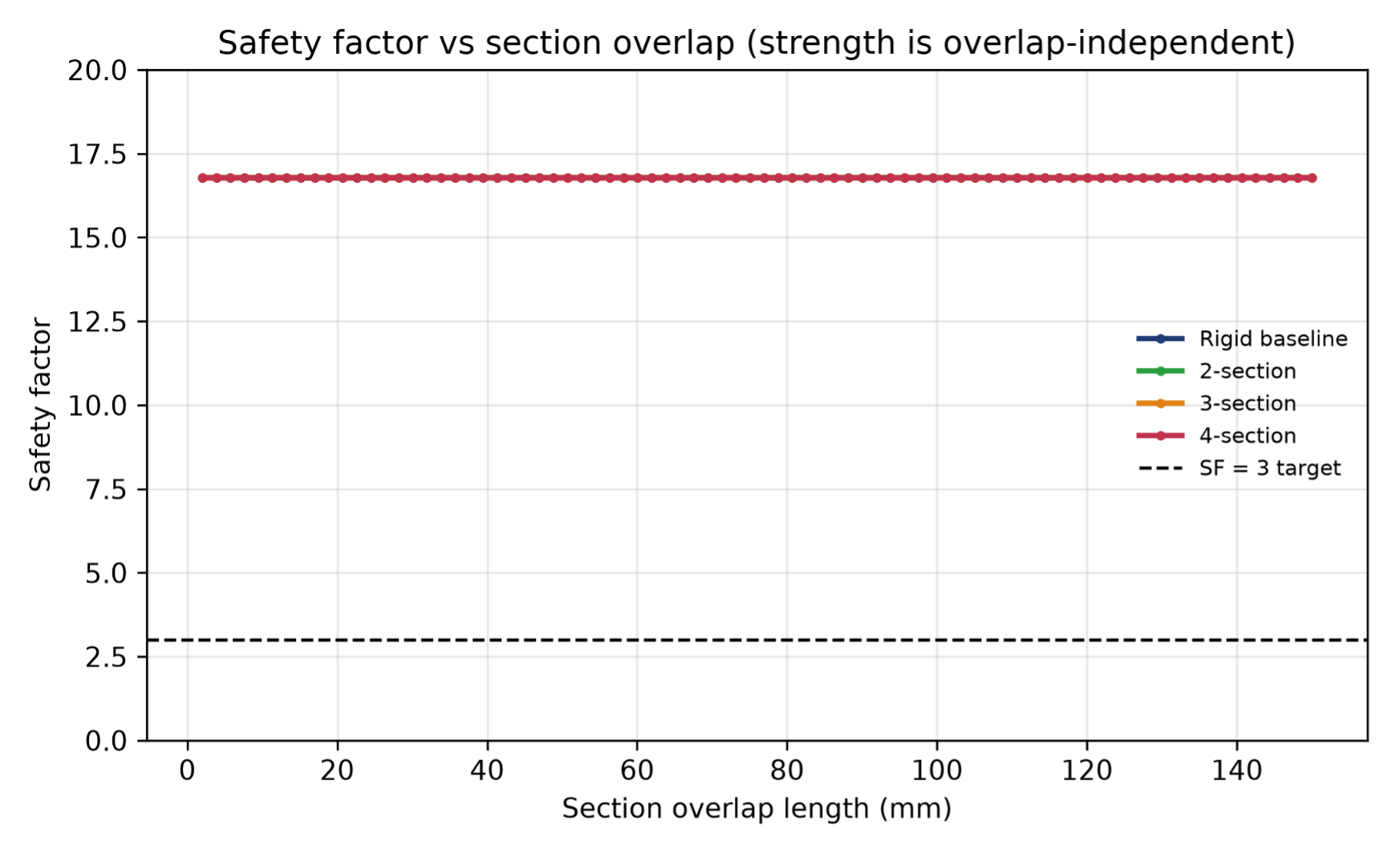
Figure 4 shows the safety factor against overlap length. The maximum bending stress is 14.3 MPa in every one of the 320 cases, independent of layout and of overlap length, and the safety factor against the 240 MPa yield stress is flat at 16.8, far above the target of 3. Cutting the ramp into two, three, or four sections and overlapping them does not change the maximum internal bending moment, which stays at PL/4 = 214.6 N·m throughout; with the moment unchanged, the stress and the safety factor do not move.
Table 1 summarises the full 320-case sweep, reporting minimum, maximum, and mean deflection and stress per layout rather than only the highlighted overlaps discussed above.
| Configuration | δ min (mm) | δ max (mm) | δ mean (mm) | σmax (MPa) | SF |
| Rigid baseline | 1.737 | 1.737 | 1.737 | 14.306 | 16.776 |
| 2-section | 1.779 | 240.433 | 6.782 | 14.306 | 16.776 |
| 3-section | 1.775 | 213.487 | 6.213 | 14.306 | 16.776 |
| 4-section | 1.801 | 359.781 | 9.305 | 14.306 | 16.776 |
Discussion
Key findings
The sweep answers both research questions with two results that were not obvious at the outset. First, the overlap controls deflection and only deflection: across a 75-fold range of overlap the deflection changed by a factor of up to 210 while the stress did not move at all. Second, the hypothesis that more sections always means worse performance is wrong. The three-section ramp, with two joints, needs less overlap than the two-section ramp, with one.
Why overlap governs serviceability and not strength
The ramp rests on two supports and carries one load, so it is statically determinate: the bending moment diagram is fixed by equilibrium alone and the maximum moment is locked at PL/4 no matter how the joints behave. The joints add rotational give, and that give appears as sag, not as extra fibre stress. The practical consequence is that a telescopic ramp of this kind does not fail by breaking. It fails by sagging past the point where it is compliant and feels safe, long before the aluminium is in any danger. The governing check for a telescopic ramp designer is therefore the deflection limit, and the safety factor, at 16.8 against a target of 3, establishes that the ramp holds the rated load without any risk of permanent bending.
Why joint position matters as much as joint count
Intuitively, it would seem that the more the sections, the larger the needed overlap must be. That is not what the data show, and the reason is the placement of the joint relative to the load. The two-section layout puts its single joint at 0.50L, directly under the mid-span load, exactly where the bending moment and the rotation demand are highest. The three-section layout keeps both of its joints away from mid-span, at 0.333L and 0.667L, where the moment is lower, so each joint is asked to do less and a shorter overlap suffices. The four-section layout is the worst of the three because the two effects stack: it has a joint under the load and it has the most joints. The simple idea that more sections is always worse is not right; what degrades the ramp is joints at the point of peak moment, compounded by their number. Every layout compared so far, however, is an evenly spaced standard grid, so joint count and joint position change together; ‘Isolating the position effect from the count effect’ below breaks that link directly.
Connection to the design
The four-section v9 concept specifies a 60 mm overlap, and its critical overlap from the sweep is 29.3 mm, so the design carries a two-fold serviceability margin and sits well inside the safe zone for the idealised 100 x 30 mm surrogate section modelled here. Because that section was fixed, before the sweep, to make the rigid baseline serviceable rather than measured from the real 100 x 25 mm channel (see ‘Geometry, material, and load’), this margin should be read accordingly. This is an independent confirmation, from first-principles mechanics, applied to a representative surrogate geometry, of a dimension that was originally chosen by judgement, and not a certified safety margin for the physical channel section itself, whose true stiffness was not computed. Two recommendations follow for telescopic ramp design in general. The minimum overlap should appear on the manufacturing drawing as a hard dimension, with end-stops set so the sections cannot extend past it in service, because a user who over-extends the ramp is silently removing its stiffness. And where the layout allows, an overlap joint should not be placed directly under the point of heaviest load; a joint kept off-centre costs less serviceability than one under the load.
Isolating the position effect from the count effect
The four-section, three-section, and two-section layouts compared above are all evenly spaced standard grids, so every layout that has more joints also happens to have a joint closer to mid-span, and joint count and joint position are confounded in that comparison. To separate them, a fourth 4-section layout was swept with the same three joints and the same 0.25L spacing between them, but the whole grid shifted so that no joint sits at 0.50L (joints at 0.35L, 0.60L, 0.85L instead of 0.25L, 0.50L, 0.75L). Its critical overlap is 26.4 mm, against 29.3 mm for the standard layout with the same joint count and spacing but a joint under the load — a roughly 10% reduction from moving the joints off-centre alone, with the number of joints held fixed. This isolates the position effect the previous section infers from a between-layout comparison and confirms it directly: it is where the joints sit, not only how many there are, that sets the critical overlap.
Sensitivity to the bearing-stiffness assumption
Because kᴄ is assumed rather than measured (see ‘The overlap joint model’), and every critical-overlap number in this paper scales with it, the full sweep was rerun with kᴄ halved and doubled. Table 2 reports the result. Halving kᴄ raises the three critical overlaps by about 40 to 45%, to 33.8, 31.8, and 41.4 mm; doubling it lowers them by about 30%, to 16.9, 16.0, and 20.7 mm. Even in the worst case tested across this range — kᴄ halved, four-section layout, critical overlap 41.4 mm — the 60 mm v9 design overlap still clears it, with a 1.45x margin. The design conclusion is therefore not fragile to a factor-of-two error in the one assumed constant, though the exact margin quoted elsewhere in this paper (2.05x for the four-section layout) is specific to the assumed kᴄ = Et and should be read as a point estimate within this wider range.
| Configuration | kc halved: crit. overlap (mm) / margin | Baseline kc: crit. overlap (mm) / margin | kc doubled: crit. overlap (mm) / margin |
| 2-section | 33.8 / 1.78x | 23.9 / 2.51x | 16.9 / 3.55x |
| 3-section | 31.8 / 1.89x | 22.5 / 2.67x | 16.0 / 3.75x |
| 4-section | 41.4 / 1.45x | 29.3 / 2.05x | 20.7 / 2.90x |
Local bearing stress at the overlap contacts
The joint model already implies a bearing force at each contact: since the transmitted moment M is reacted by a force couple with lever arm Lₒᵥ (see ‘The overlap joint model’), the contact force is F = M/Lₒᵥ, and M = PL/4 = 214.6 N·m is constant everywhere in the sweep. Dividing F by an assumed contact patch equal to the full rail width and wall thickness (100 mm x 2 mm = 200 mm²) gives a first-order bearing stress. At the reported critical overlaps this stress is 37 to 48 MPa, 15 to 20% of the 240 MPa yield stress; at the 60 mm design overlap it is 18 MPa, 7.5% of yield. Both are comfortably below yield, supporting the claim elsewhere in this paper that strength does not govern in the serviceable range. Below about 4.5 mm of overlap, however, this estimate exceeds the 240 MPa yield stress outright (536 MPa at the 2 mm sweep minimum, more than double yield), meaning that portion of the sweep is invalidated by local bearing failure as well as by the large-deflection breakdown noted above — a second, independent reason that low-overlap region is shown for completeness only and carries no design conclusion.
Point-spring versus distributed overlap idealisation
The overlap is modelled as a single zero-length rotational spring at one point, even though the physical engagement spans a finite length Lₒᵥ. To bound how much this idealisation matters, each point spring in the four-section layout — the layout with the sharpest kink in Figure 2 — was replaced with a proxy pair of springs at the two physical ends of the engagement length, each twice as stiff, with the ordinary beam element bridging the overlapped stub of rail between them. This is not a physical model of bearing contact, only a bound on the simplification. At overlaps of 20, 29.3, and 60 mm, the distributed proxy deflects 1.1 to 1.5% less than the point-spring model — the point-spring idealisation is, if anything, mildly conservative rather than optimistic, and the effect is small next to the sensitivity to kᴄ documented above.
Limitations
The model is linear-elastic Euler-Bernoulli beam theory with a static point load held at mid-span, the worst case for deflection but not a full description of a wheelchair rolling along the span, though the load-position sweep in Results confirms mid-span governs across the range this paper’s thresholds are drawn from. The overlap is condensed into a single rotational spring through the force-couple model, with the bearing stiffness assumed as kᴄ = Et rather than measured; the critical overlaps scale with that constant, so they should be read as model estimates, not certified values. A halving or doubling of kᴄ moves the three critical overlaps by roughly +40% to -30% (Table 2), and even in the worst case tested the 60 mm design overlap still clears the critical overlap, with a 1.45x margin. Contact friction, local crushing of the thin wall, and the perforated base of the real section are all outside the model, though a first-order bearing-stress check suggests local crushing is not governing in the serviceable range (see ‘Local bearing stress at the overlap contacts’). The effective 30 mm section depth was fixed so the rigid baseline is serviceable, which makes the comparison between layouts clean but means the absolute deflections of the real channel section will differ, and the roughly two-fold design margin reported above belongs to this idealised surrogate section, not to a certified analysis of the physical channel. The L/360 serviceability threshold itself is a general structural criterion, not one derived for wheelchair rollability specifically; a ramp- and wheelchair-specific deflection or slope-change criterion is future human-factors work this study does not attempt. Nor has the joint law kᵣ = ½kᴄLₒᵥ² been checked against a physical measurement of an actual overlap joint — every verification check in this paper compares the code against closed-form mathematics, not against hardware (see ‘Verification procedure’). Because of that, every absolute overlap threshold reported in this paper — the three critical overlaps, the bearing-stress estimates, and the two-fold design margin — should be read as the output of an assumed mechanical model, not as a validated design value, until the bench test proposed below is carried out. These simplifications are the price of isolating one variable cleanly, and they mark the boundary of what the numbers claim.
Future work
The 900 N case has since been run directly: raising the rated load from 699 N to 900 N raises the three critical overlaps to 32.4 mm (two-section), 30.5 mm (three-section), and 39.6 mm (four-section) — each larger than its 699 N counterpart, as expected, and every one of them still below the 60 mm v9 design overlap, with a margin of 1.5x in the worst case. The safety factor at 900 N is 13.0, still far above the target of 3. The stronger extension is physical: a bench test of two overlapping channel sections under a central load would measure the real moment-rotation behaviour of the overlap, recovering kᴄ directly at overlaps of 20, 30, 40, and 60 mm from kᵣ = M/Δθ given an applied moment and the resulting relative rotation, testing both the assumed Lₒᵥ² scaling and the magnitude of kᴄ, and would turn the model estimates into certified minimums.
Closing Thought
A telescopic ramp lives or dies by a dimension that never appears in accessibility codes: the length over which its sections engage. This study shows that the dimension can be modelled with nothing more than beam theory and a rotational spring, that it controls serviceability rather than strength, and that where the joints sit matters as much as how many there are. The result is a floor a designer can enforce, an overlap length written on a drawing, so that a ramp that folds flat for the boot of a car still feels like solid ground under a wheelchair.
Acknowledgments
The author wishes to thank Dr Nishchal Dwivedi of Athena Education for research mentorship and guidance throughout this study.
References
- Bureau of Indian Standards. IS 7480: Ramps for physically handicapped persons — code of practice. Bureau of Indian Standards, New Delhi, 2004. [↩] [↩]
- Government of India. Harmonised guidelines and standards for universal accessibility in India. Central Public Works Department, https://cpwd.gov.in. 2021. [↩] [↩]
- J. A. Sanford, M. F. Story, M. L. Jones. An analysis of the effects of ramp slope on people with mobility impairments. Assistive Technology. Vol. 9, pg. 22–33, 1997, https://doi.org/10.1080/10400435.1997.10132293. [↩]
- M. J. Frye, G. A. Morris. Analysis of flexibly connected steel frames. Canadian Journal of Civil Engineering. Vol. 2, pg. 280–291, 1975, https://doi.org/10.1139/l75-026. [↩]
- W. F. Chen, N. Kishi. Semirigid steel beam-to-column connections: data base and modeling. Journal of Structural Engineering. Vol. 115, pg. 105–119, 1989, https://doi.org/10.1061/(ASCE)0733-9445(1989)115:1(105). [↩] [↩]
- N. Kishi, W. F. Chen. Moment-rotation relations of semirigid connections with angles. Journal of Structural Engineering. Vol. 116, pg. 1813–1834, 1990, https://doi.org/10.1061/(ASCE)0733-9445(1990)116:7(1813). [↩]
- R. Bjorhovde, A. Colson, J. Brozzetti. Classification system for beam-to-column connections. Journal of Structural Engineering. Vol. 116, pg. 3059–3076, 1990, https://doi.org/10.1061/(ASCE)0733-9445(1990)116:11(3059). [↩]
- European Committee for Standardization. EN 1993-1-8, Eurocode 3: design of steel structures, part 1-8: design of joints. CEN, Brussels, 2005. [↩] [↩]
- S. W. Jones, P. A. Kirby, D. A. Nethercot. The analysis of frames with semi-rigid connections — a state-of-the-art report. Journal of Constructional Steel Research. Vol. 3, pg. 2–13, 1983, https://doi.org/10.1016/0143-974X(83)90017-2. [↩]
- M. Savković, M. Gašić, G. Pavlović, R. Bulatović, N. Zdravković. Stress analysis in contact zone between the segments of telescopic booms of hydraulic truck cranes. Thin-Walled Structures. Vol. 85, pg. 332–340, 2014, https://doi.org/10.1016/j.tws.2014.09.009. [↩]
- D. Derlukiewicz, G. Przybyłek. Chosen aspects of FEM strength analysis of telescopic jib mounted on mobile platform. Automation in Construction. Vol. 17, pg. 278–283, 2008, https://doi.org/10.1016/j.autcon.2007.05.007. [↩]
- J. Xu, Y. Zhuo, Z. Qi, G. Wang, T. Zhao, T. Wang. Instability load analysis of a telescopic boom for an all-terrain crane. Mechanical Sciences. Vol. 13, pg. 991–1009, 2022, https://doi.org/10.5194/ms-13-991-2022. [↩]
- T. Storr, J. Spicer, P. Frost, S. Attfield, C. D. Ward, L. L. Pinnington. Design features of portable wheelchair ramps and their implications for curb and vehicle access. Journal of Rehabilitation Research and Development. Vol. 41, pg. 443–452, 2004, https://doi.org/10.1682/jrrd.2003.06.0091. [↩]
- B. W. Lenggana, A. Nugroho, Ubaidillah. Structural simulation of wheelchair ramp using finite element method. Journal of Mechanical Engineering Science and Technology. Vol. 8, pg. 306–321, 2024, https://doi.org/10.17977/um016v8i12024p306. [↩]
- S. P. Timoshenko, J. M. Gere. Mechanics of materials. Van Nostrand Reinhold, New York, 1972. [↩] [↩] [↩]
- W. F. Chen, E. M. Lui. Structural stability: theory and implementation. Elsevier, New York, 1987. [↩]
- W. L. Oberkampf, T. G. Trucano. Verification and validation in computational fluid dynamics. Progress in Aerospace Sciences. Vol. 38, pg. 209–272, 2002, https://doi.org/10.1016/S0376-0421(02)00005-2. [↩] [↩] [↩]
- American Society of Mechanical Engineers. ASME V&V 10-2006: guide for verification and validation in computational solid mechanics. ASME, New York, 2006. [↩]
- C. R. Harris, K. J. Millman, S. J. van der Walt, R. Gommers, P. Virtanen, D. Cournapeau, E. Wieser, J. Taylor, S. Berg, N. J. Smith, R. Kern, M. Picus, S. Hoyer, M. H. van Kerkwijk, M. Brett, A. Haldane, J. F. del Rio, M. Wiebe, P. Peterson, P. Gerard-Marchant, K. Sheppard, T. Reddy, W. Weckesser, H. Abbasi, C. Gohlke, T. E. Oliphant. Array programming with NumPy. Nature. Vol. 585, pg. 357–362, 2020, https://doi.org/10.1038/s41586-020-2649-2. [↩]
- J. D. Hunter. Matplotlib: a 2D graphics environment. Computing in Science & Engineering. Vol. 9, pg. 90–95, 2007, https://doi.org/10.1109/MCSE.2007.55. [↩]
- W. S. Miller, L. Zhuang, J. Bottema, A. J. Wittebrood, P. De Smet, A. Haszler, A. Vieregge. Recent development in aluminium alloys for the automotive industry. Materials Science and Engineering: A. Vol. 280, pg. 37–49, 2000, https://doi.org/10.1016/S0921-5093(99)00653-X. [↩]
- I. Čudina, D. Skejić. Extruded aluminium alloy members subjected to axial compression — a comprehensive review. Engineering Structures. Vol. 326, pg. 119536, 2025, https://doi.org/10.1016/j.engstruct.2024.119536. [↩]
- J. Kalin, A. Žnidarič, A. Anželin, M. Kreslin. Measurements of bridge dynamic amplification factor using bridge weigh-in-motion data. Structure and Infrastructure Engineering. Vol. 18, pg. 1164–1176, 2022, https://doi.org/10.1080/15732479.2021.1887291. [↩]
- International Organization for Standardization. ISO 7176-8:2014: wheelchairs — part 8: requirements and test methods for static, impact and fatigue strengths. ISO, Geneva, 2014. [↩]
- T. V. Galambos, B. Ellingwood. Serviceability limit states: deflection. Journal of Structural Engineering. Vol. 112, pg. 67–84, 1986, https://doi.org/10.1061/(ASCE)0733-9445(1986)112:1(67). [↩]
- H. Wilson-Jene, R. E. Cowan, J. Pearlman. A novel approach to directly measuring wheel and caster rolling resistance accurately predicts user-wheelchair system-level rolling resistance. Journal of Rehabilitation and Assistive Technologies Engineering. Vol. 10, 2023, https://doi.org/10.1177/20556683231180877. [↩]
- S. Zhang, J. Zhou, Y. H. Chui. Deflection criteria for controlling timber floor vibrations: a 200-year evolution. Engineering Structures. Vol. 326, pg. 119370, 2025, https://doi.org/10.1016/j.engstruct.2024.119370. [↩]
- W. McGuire, R. H. Gallagher, R. D. Ziemian. Matrix structural analysis. 2nd ed., John Wiley & Sons, New York, 2000. [↩]
- B. Biondi, S. Caddemi. Euler-Bernoulli beams with multiple singularities in the flexural stiffness. European Journal of Mechanics – A/Solids. Vol. 26, pg. 789–809, 2007, https://doi.org/10.1016/j.euromechsol.2006.12.005. [↩]
- G. Failla, A. Santini. On Euler-Bernoulli discontinuous beam solutions via uniform-beam Green’s functions. International Journal of Solids and Structures. Vol. 44, pg. 7666–7687, 2007, https://doi.org/10.1016/j.ijsolstr.2007.05.003. [↩]