
Abstract
Inefficiencies and manual errors in generating Peddimat programs within the legacy software (v1.08.07) limit productivity in fabrication workflows. This study presents an Excel-based VSTO Add-In, developed with Visual Studio 2022, Microsoft Excel 365, and AutoCAD 2026, for the first time to create Peddimat programs and generate AutoCAD Dwg or Dxf files for verification and nesting programs for Peddimat plate processors. Key contributions include interpretation of Peddimat program structure, a fluent builder interface with recursive design patterns for object construction, dependency injection for VSTO Add-In architecture, and custom .NET Framework class libraries supporting dynamic formulas, unit conversion, and clip management of plates. A specialized Excel template enables rapid insertion of hole rows and types using predefined patterns, streamlining data preparation for both Peddimat programs and AutoCAD Dwg files. Performance evaluation shows a 20% reduction in program creation time, along with a lower error rate and improved verification efficiency for components with many holes. These results demonstrate that the proposed system enhances usability, reduces errors, and provides a practical, scalable framework for integrating engineering automation tools into Excel-based environments.
Keywords: Peddimat Programs, .NET Framework Class Library, User-Defined Functions (UDFs), VSTO Add-in, Excel Add-ins, AutoCAD Dwg, C#.NET
Introduction
Peddinghaus Corporation is a global leader in machine-tool technology for structural steel and plate fabrication, offering legacy software used to process components such as plates, angles, channels, beams, and tubes. While this software remains functional and well-integrated with Peddinghaus hardware, it exhibits inefficiencies in the generation and verification of Peddimat programs, particularly for large-scale drilling operations. This issue is inherent to legacy software1.
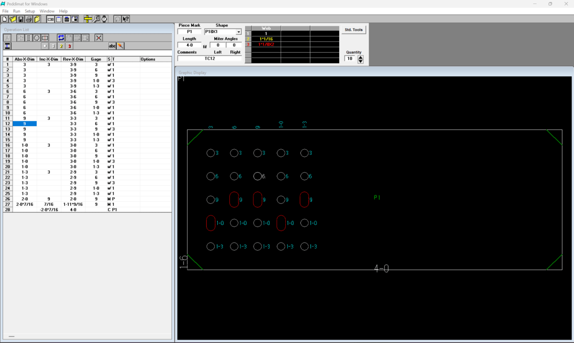
The legacy List window displays only Abs-X-Dim, Inc-X-Dim, Rev-X-Dim, Gage (Abs-Y-Dim), S (tool type), T (tool number) and Options for holes, slots and copes. Because Inc-Y-Dim values aren’t shown, programmers must manually determine and enter Abs-Y-Dim values for the Gage field instead of using the incremental Y-dimensions provided in the shop drawings when the vertical spacings vary. Similarly, the absence of a Rev-Y-Dim column requires programmers to manually calculate reverse Y-dimensions when verifying programs against drawings. Most manual errors are caused by miscalculations in the Rev-Y-Dim. The legacy List window provides a Matrix (Rectangle) pattern that allows programmers to specify the number of rows, columns, and pitch to generate hole data lines. The first step is to create the initial hole data line since the pattern will be applied according to this reference. In addition, the row and column pitches are constant within the pattern; if shop drawings require variable horizontal or vertical spacing, programmers must manually modify the hole data lines after the pattern is applied. Because the List window provides no positional references between hole data lines, changes made to one hole position affect only that individual line. As a result, programmers must adjust hole positions and rely heavily on the select, copy, and paste functions. For enormous quantities of holes, the Matrix pattern generates numerous hole data lines, significantly increasing manual operations. The Matrix (Rectangle) pattern can be cached by entering its corresponding pattern number; however, in the legacy system (v1.08.07), reloading it via shortcut keys is not possible. Moreover, the caching functions provide little efficiency gain, particularly when vertical or horizontal spacings vary. Another shortcoming is that when programmers modify the Abs-X-Dim, Inc-X-Dim, or Rev-X-Dim dimension, the cursor automatically moves to the Gage column, even when the Gage value is already correct. Although the List window provides the cells, programmers still must constantly use calculators to determine the dimensions and manually enter them into the cells. These limitations introduce substantial manual operations, computation and increase the likelihood of programming errors, which affects small and medium-sized fabricators that continue to rely on traditional AutoCAD-based workflows.
Another major limitation of the legacy software is its inability to generate AutoCAD Dwg files. Since modern plate-processing nesting programs require AutoCAD Dxf or DSTV files, programmers must rely on separate systems to produce Dwg outputs, further fragmenting the workflow2‘3‘4‘5‘6‘7‘8‘9.
This paper addresses these challenges by proposing, for the first time, an integrated workflow that enhances both the creation and verification of Peddimat programs while enabling the generation of corresponding AutoCAD Dwg files from the same dataset10. By incorporating spreadsheet templates with patterns, formula-driven inputs, and AutoCAD, the proposed solution aims to increase operational efficiency and reduce errors in structural steel fabrication.
Approaches
Microsoft Excel provides a flexible and extensible platform for computational automation through native Excel Add-ins and COM Add-ins11. Excel Add-ins enable the creation of custom formulas (UDFs) that automatically update with cell value changes, supporting real-time, data-driven calculations. COM Add-ins developed using Visual Studio Tools for Office (VSTO) further extend this functionality by integrating advanced user interface components, such as Ribbon controls, directly within Excel. This integrated environment offers a user-friendly experience, reduces the learning curve, and eliminates the need to switch between applications.
Based on these advantages, an Excel VSTO Add-in is chosen over a standalone desktop application, leveraging Excel’s widespread adoption as a standard engineering tool. Excel’s native spreadsheet interface is used for input management, formula computation, and visualization, while the VSTO layer manages automation tasks, including data processing, program generation, and file export. This design minimizes development overhead, ensures system compatibility, and enables direct linkage between calculated data and generated Peddimat program outputs.
Using this approach, users can define hole patterns, apply formula-driven dimensions, and adjust IncX and IncY parameters to automatically compute X and Y coordinates for fabrication programs. The same dataset is then used to generate both Peddimat programs and AutoCAD Dwg files, which can be programmatically created and converted to Dxf format without manually opening AutoCAD. This enables integration with Peddinghaus plate processors and allows direct visual comparison between generated drawings and shop drawings for verification. Overall, this architecture reduces manual effort, minimizes errors, and enhances productivity and product quality in structural steel fabrication.
Peddimat File Structure
With legacy Peddimat software, sample program gradually is modified, saving it under different names, and then compare it with the original using NotePad++ and AISC shapes database to understand the meanings of each line in the program. Peddimat program is the proprietary legacy programming format used by Peddinghaus CNC machines to define drilling, and cutting operations. Each Peddimat program is a structured ASCII text file consisting of header data, machining block, and termination character. The syntax follows a strict positional and numerical layout that controls both toolpath and geometry execution. There are four lines for header data in Peddimat program. The definition of the first three lines are shown in Table 1.
| Position | Value | Definition | Comments |
| First line | B12 beam | piece mark and comments | maximum 8 characters for piece mark |
| Second line | W12X50 | shape | |
| Third line | B | type | B for beams, C for channels, L for angles and P for plates |
| Fourth line | 1 3111.5 95.25 2063.75 158.75 0 1 2 15240 254 238.125 269.875 206.375 238.125 269.875 238.125 238.125 269.875 0 0 0 0 0 0 0 0 0 0 0 0 0 0 0 0 0 0 | ||
The definition of the fourth line is shown in Table 2.
| Postion | Value | Definition | Postion | Value | Definition |
| 1 | 1 | quantity | 11 | 238.125 | bottom flange tool 1 size |
| 2 | 3111.5 | web height | 12 | 269.875 | top flange tool 1 size |
| 3 | 95.25 | web thickness | 13 | 206.375 | web tool 2 size |
| 4 | 2063.75 | flange width | 14 | 238.125 | bottom flange tool 2 size |
| 5 | 158.75 | flange thickness | 15 | 269.875 | top flange tool 2 size |
| 6 | 0 | unknown | 16 | 238.125 | web tool 3 size |
| 7 | 1 | left miter angle | 17 | 238.125 | bottom flange tool 3 size |
| 8 | 2 | right miter angle | 18 | 269.875 | top flange tool 3 size |
| 9 | 15240 | length | 19 | 18@0 | reserved for future uses |
| 10 | 254 | web tool 1 size |
The machining block includes hole data lines, mark data lines and cope lines. Table 3 shows partial of machining block.
| Value | Description | Definition |
| 56 | number lines of machine block plus 1 | number lines of machine block + 1 |
| 25400 53975.1010 | hole data Line | (25400 53975) is X coordinate and Y coordinate; “.1010” is Web Tool 1, and 53975.1010 is formatted with left padding to 12 characters. |
| 16400 2031.0020 | mark data line | (16400, 2031) are the X and Y coordinates; “.0020” represents the mark “0”, “.0020–.0090” map to digits “0–9”, and “.0100–.0360” map to letters “A–Z”. The value 2031.0020 is left-padded to 12 characters. |
| 1462590 448500.6000 p10261 | cope lines | (1,462,590, 448,500) are the X and Y coordinates; “.6000” represents the cope named P10261. |
| SUB | special character | End of the program |
This research only focuses on plate Peddimat programs creation and AutoCAD Dwg files generation12‘13. Future work should include all AISC shapes.
Implementation
Design Architecture
A VSTO Add-in project follows a layered architecture designed to separate user interface elements from application logic and Office automation. PlantUML (v1.2025.10) and Visual Studio Code 2022 are used to create design architecture by generating puml files14‘15. Figure 1 illustrates the application entry point and user interface layer of the Peddimat Excel add-in. This add-in serves as the VSTO add-in entry point, configuring injection through Microsoft.Extensions.DependencyInjection during startup to register all services, builders, and repository implementations as transient based on their lifecycle requirements16‘17. The Ribbon class provides the Excel ribbon interface with custom buttons that trigger the add-in’s core operations for generating Peddimat programs and AutoCAD Dwg files. The plateCopes Windows form offers a dialog interface for user interactions specific to cope operations on structural steel plates. This architecture establishes a clean separation between UI concerns and business logic while enabling testability through constructor-based dependency injections.
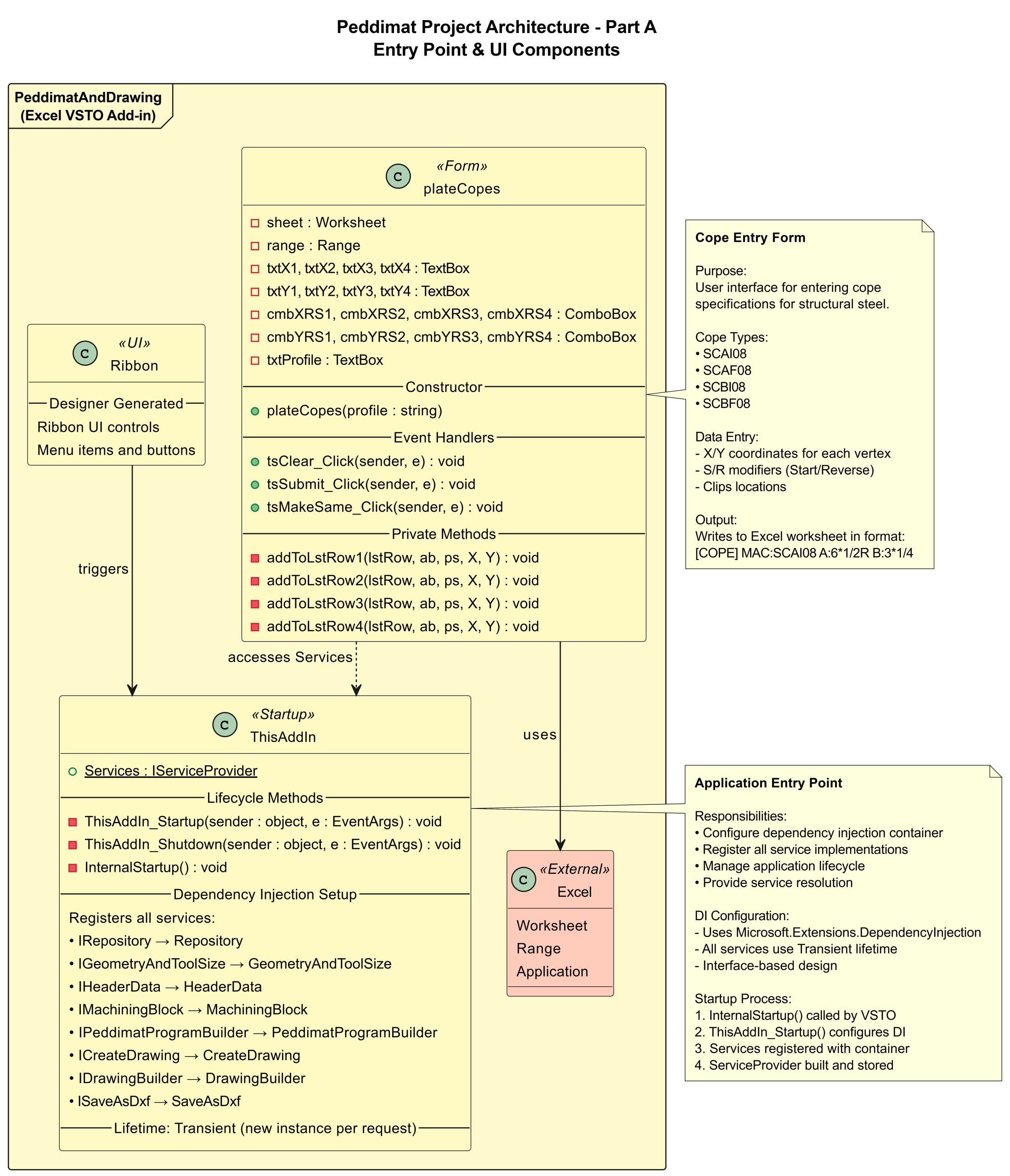
Figure 2 represents the core business logic layer of the Peddimat system, implementing seven service interfaces that encapsulate domain-specific operations for Peddimat program and CAD integration. The services transform Excel worksheet data into structured formats: GeometryAndToolSize converts structural member dimensions and tool specifications, HeaderData assembles program metadata, and MachiningBlock generates CNC hole positions and cope sizes with proper scaling. Pattern automates the creation of hole patterns in Excel, while QuickOperation provides worksheet manipulation utilities. CreateDrawing orchestrates AutoCAD Dwg files generation with geometric primitives, and SaveAsDxf manages Dxf file export. Each service follows dependency injection patterns, accepting repository and converter dependencies through constructors to maintain loose coupling and testability. This diagram shows all service interfaces and implementations and business logics for geometry, headers, drilling, burning, drawing, and patterns.
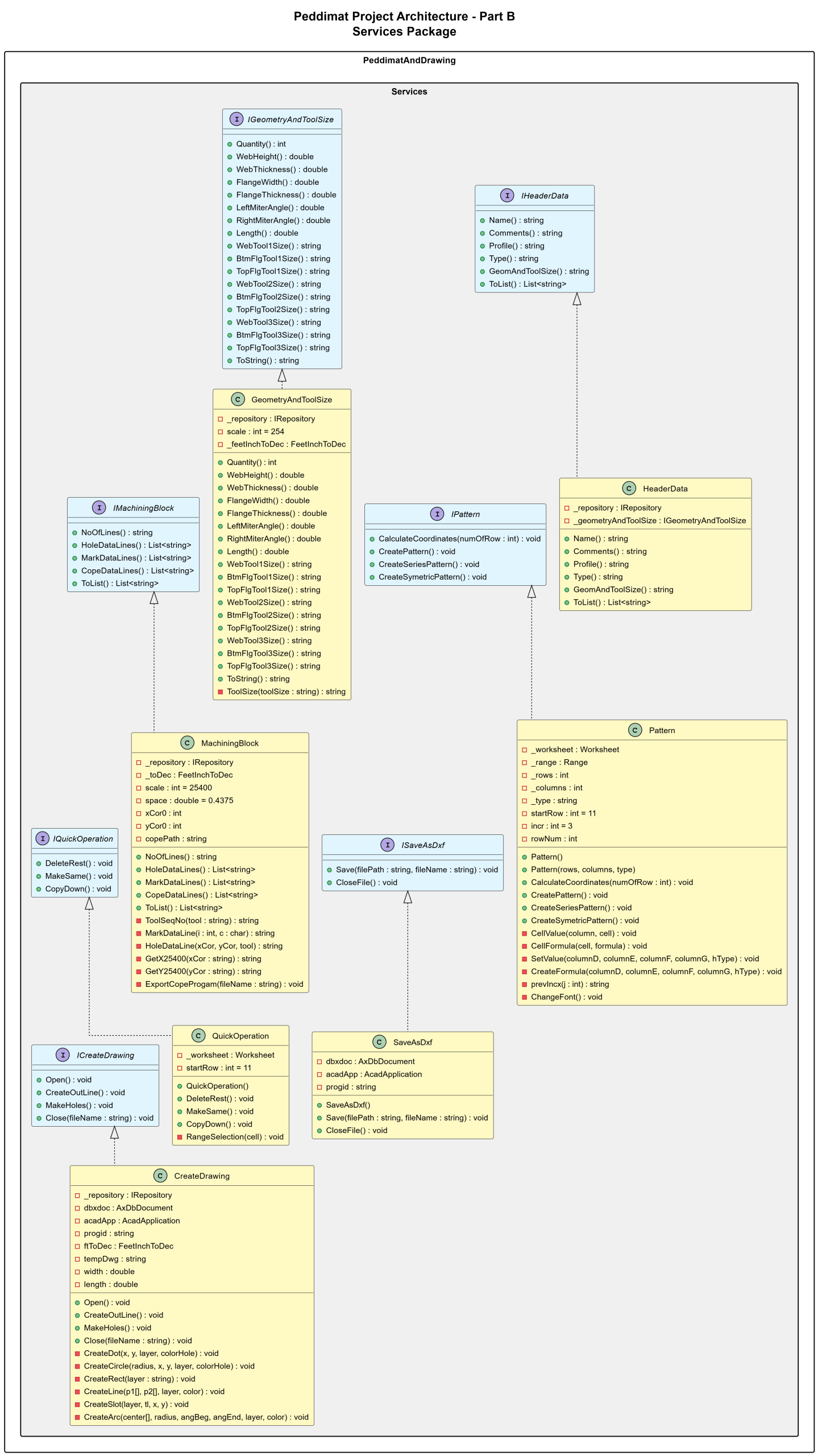
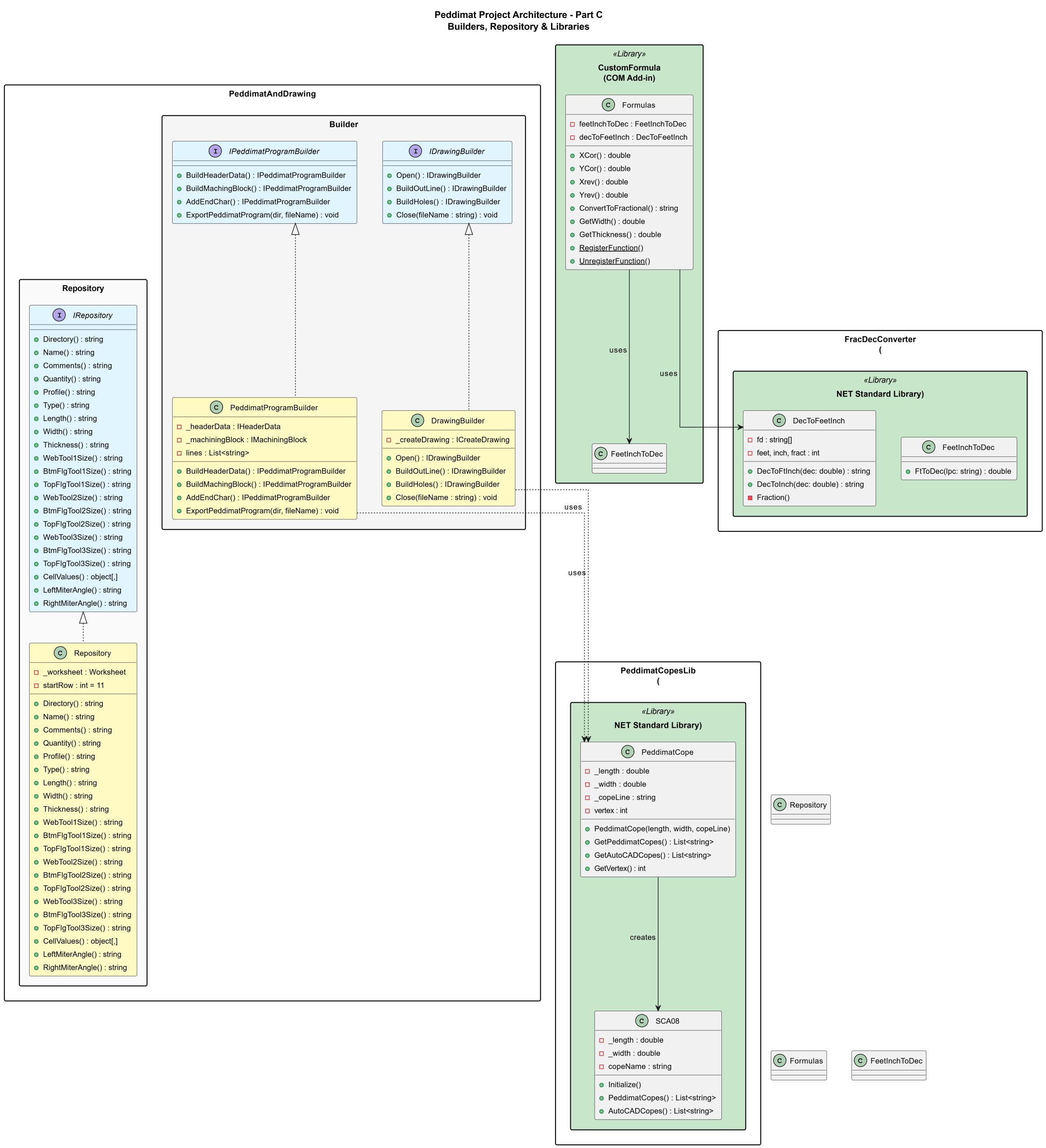
Figure 3 demonstrates the data orchestration and infrastructure layer of the Peddimat system. The Builder implements the Builder pattern to construct Peddimat program files and AutoCAD Dwg files through a fluent interface. The Repository provides centralized data access to Excel worksheet cells, abstracting the underlying data source from spreadsheet template. Three external .NET libraries extend the system: PeddimatCopesLib handles cope with geometry calculations for plates, FracDecConverter manages bidirectional conversions between fractional inches and decimal values, and CustomFormula provides Excel UDF functions for coordinate transformations and dimensional conversions used in the worksheet interface.
This diagram shows builder pattern PeddimatProgramBuilder, DrawingBuilder and data access abstraction repository and libraries PeddimatCopesLib, FracDecConverter, and CustomFormula.
All source code in the design architecture was developed using Visual Studio 2022 C#.NET, Microsoft 365 Excel, and AutoCAD 2026, running on the Windows 11 operating system18‘19‘20‘21.
Computational Logic
Peddimat and AutoCAD Coordinate Systems
In the Peddimat coordinate system, a hole located at (X, Y) corresponds to (X, W – Y) in the AutoCAD coordinate system, where W is the width of the piece. The Excel spreadsheet template uses the Peddimat coordinate system for defining X and Y coordinates. As shown in Figure 4, the origin (0, 0) in Peddimat is at the upper-left corner whereas in Figure 5, the AutoCAD coordinate system places the origin at the lower-left corner.

Pseudocode for X and Y Coordinates Calculation with Custom Formulas (UDFs)
The Formulas class, located in the CustomFormula namespace, contains all custom formulas that can be used in an Excel spreadsheet after building the project and integrating the resulting Excel Add-in. The FeetInchToDec and DecToFeetInch classes are responsible for converting between fractional and decimal values for English units within the Formulas class. The formulas below are used to determine the X and Y coordinates.
FUNCTION XCor(len, prevXcor, incX, startX, prevTool, tool)
DECLARE xTemp
IF incX is null or empty THEN
incX ← “0”
END IF
REMOVE leading and trailing spaces from len
REMOVE leading and trailing spaces from incX
IF (prevXcor equals “X” OR prevTool equals “TOOL”) AND startX is not “R” THEN
IF incX contains “,” OR incX CONTAINS “@” THEN
xTemp ← Cor(incX)
ELSE
xTemp ← ConvertFeetInchesToDecimal(incX)
END IF
ELSE IF first character of prevTool is not equal to first character of tool OR startX equals “S” THEN
IF incX contains “,” OR incX CONTAINS “@” THEN
xTemp ← Cor(incX)
ELSE
xTemp ← ConvertFeetInchesToDecimal(incX)
END IF
ELSE IF startX equals “R” THEN
xTemp ← ConvertFeetInchesToDecimal(len) minus ConvertFeetInchesToDecimal(incX)
ELSE
IF incX contains “,” OR incX CONTAINS “@” THEN
xTemp ← Cor(incX)
xTemp ← xTemp + ConvertFeetInchesToDecimal(prevXcor)
ELSE
xTemp ← ConvertFeetInchesToDecimal(prevXcor) plus ConvertFeetInchesToDecimal(incX)
END IF
END IF
RETURN xTemp rounded to 6 decimal places
END FUNCTION
FUNCTION Cor(inc)
SPLIT inc by “,” into incParts (ignore empty values)
temp ← 0
FOR EACH part IN incParts DO
IF part contains “@” THEN
multiplier ← integer before “@”
value ← substring after “@”
temp ← temp + (multiplier × ConvertFeetInchesToDecimal(value))
ELSE
temp ← temp + ConvertFeetInchesToDecimal(part)
END IF
END FOR
RETURN temp rounded to 6 decimal places
END FUNCTION
FUNCTION YCor(width, prevYcor, incY, startY, prevTool, tool)
DECLARE yTemp ← 0
IF incY is null or empty THEN
incY ← “0”
END IF
REMOVE leading and trailing spaces from incY
IF (prevYcor equals “Y” OR prevTool equals “TOOL”) AND startY is not “R” THEN
IF incY contains “,” OR incY CONTAINS “@” THEN
yTemp ← Cor(incY)
ELSE
yTemp ← ConvertFeetInchesToDecimal(incY)
END IF
ELSE IF first character of prevTool is not equal to first character of tool OR startY equals “S” THEN
IF incY contains “,” OR incY CONTAINS “@” THEN
yTemp ← Cor(incY)
ELSE
yTemp ← ConvertFeetInchesToDecimal(incY)
END IF
ELSE IF startY equals “R” THEN
yTemp ← ConvertFeetInchesToDecimal(width) minus ConvertFeetInchesToDecimal(incY)
ELSE
IF incY contains “,” OR incY CONTAINS “@” THEN
yTemp ← Cor(incY)
yTemp ← yTemp + ConvertFeetInchesToDecimal(prevYcor)
ELSE
yTemp ← ConvertFeetInchesToDecimal(prevYcor) plus ConvertFeetInchesToDecimal(incY)
END IF
END IF
RETURN yTemp rounded to 6 decimal places
END FUNCTION
Where len represents the length of the part, width represents the width of the part, prevXcor and prevYcor represent the previous X and Y coordinates respectively, incX and incY represent the spacing in the X and Y directions, and tool represents the tool type.
Holes Patterns
The Pattern class (PeddimatAndDrawing\Services\Pattern.cs) implements IPattern and automates populating an Excel worksheet via Microsoft.Office.Interop.Excel: it stores pattern parameters (_rows, _columns, _type) and a Worksheet reference, then generates a rectangular pattern by iterating columns and rows in CreatePattern(), writing cell values and R1C1 formulas with CellValue/CellFormula, computing derived coordinates in CalculateCoordinates(), and finally applying font formatting in ChangeFont(). Functions SetValue, CreateFormula, and prevIncx centralize cell assignments and relative-reference formula creation, while Helper.LastRow() + 1 defines the insertion start. The class relies on project utilities (e.g., Helper) and custom Excel formulas (e.g., XCor, YCor) and assumes a VSTO add-in context via Globals.ThisAddIn. See the following sample code:
public void CalculateCoordinates(int numOfRow) {
CellFormula(“A” + numOfRow, “=ConvertToFractional(XCor(WL,R[-1]C,RC[3],RC[4],R[-1]C[8],RC[8]))”);
CellFormula(“B” + numOfRow, “=ConvertToFractional(YCor(WH,R[-1]C,RC[4],RC[5],R[-1]C[7],RC[7]))”);
CellFormula(“C” + numOfRow, “=ConvertToFractional(Xrev(WL,RC[-2],RC[1],RC[2]))”);
CellFormula(“H” + numOfRow, “=ConvertToFractional(Yrev(WH,RC[-6],RC[-2],RC[-1]))”);
}
public void CreatePattern() {
rowNum = Helper.LastRow();
for (int m = 1; m <= _columns; m++) {
for (int n = 1; n <= _rows; n++) {
rowNum++;
if (m == 1){
if (n == 1)
SetValue(incr, “S”, incr, “S”, _type);
else if (n == 2)
SetValue(0, “”, incr, “”, _type);
else
CreateFormula(“”, “”, prevIncx(1), “”, _type);
}
else {
if (n == 1 && m == 2)
CreateFormula(incr.ToString(), “”, prevIncx(_rows), prevIncx(_rows), prevIncx(_rows));
else if (n == 1)
CreateFormula(prevIncx(_rows), “”, prevIncx(_rows), prevIncx(_rows), prevIncx(_rows));
else
CreateFormula(prevIncx(_rows), “”, prevIncx(_rows), “”, _type);
}
CalculateCoordinates(rowNum);
}
}
ChangeFont();
}
private void CellValue(string column, string cell) {
_range = _worksheet.get_Range(cell, Type.Missing);
_range.Value2 = column;
_range.HorizontalAlignment = -4108;
}
private void CellFormula(string cell, string formula) {
_range = _worksheet.get_Range(cell, Type.Missing);
_range.Activate();
_range.FormulaR1C1 = formula;
_range.HorizontalAlignment = -4108;
}
private void SetValue(double columnD, string columnE, double columnF, string columnG, string hType) {
CellValue(columnD.ToString(), “D” + rowNum);
CellValue(columnE, “E” + rowNum);
_range = _worksheet.get_Range(“F” + rowNum, Type.Missing);
if (columnF == 0)
_range.Value2 = “”;
else
_range.Value2 = columnF.ToString();
_range.HorizontalAlignment = -4108;
CellValue(columnG, “G” + rowNum);
CellValue(hType, “I” + rowNum);
}
private void CreateFormula(string columnD, string columnE, string columnF, string columnG, string hType) {
if (string.IsNullOrEmpty(columnD))
columnD = “0”;
CellFormula(“D” + rowNum, columnD);
CellFormula(“E” + rowNum, columnE);
CellFormula(“F” + rowNum, columnF);
CellFormula(“G” + rowNum, columnG);
CellValue(hType, “I” + rowNum);
}
private string prevIncx(int j) {
return “=R[-” + j + “]C”;
}
Plate Clips
Corner plate clips are widely used in the construction and bridge‑building industries. In the spreadsheet template, four standard copes are provided for generating both Peddimat programs and AutoCAD Dwg files. To eliminate the need for manually creating clips in AutoCAD or drawing them line‑by‑line in Peddimat, a C# class library PeddimatCopesLib has been developed to automate these tasks. Users simply enter the required values in the form, submit the data to the spreadsheet, and then quickly generate the corresponding Peddimat program and AutoCAD Dwg file. This approach provides an efficient way to produce copes for Peddimat and AutoCAD. Building and maintaining a cope library significantly improves the workflow for creating Peddimat programs and AutoCAD Dwg files, especially those used in the nesting system of the Peddinghaus plate processors. See Figure 6.
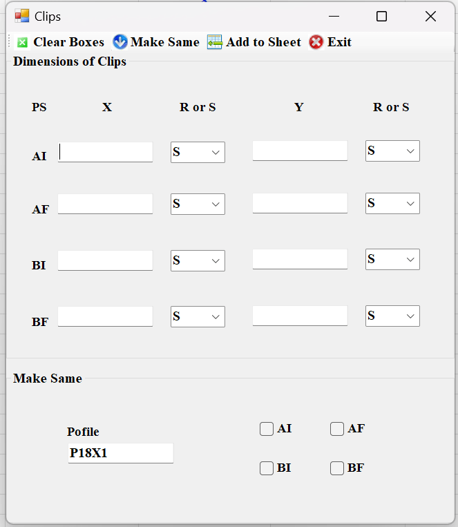
In the form, AI and AF represent the top and bottom clip dimensions on the left‑hand side, while BI and BF represent the top and bottom clip dimensions on the right‑hand side. X denotes the horizontal dimension and Y denotes the vertical dimension of the plate clips. Clip dimensions can also be entered in their reversed orientation by selecting “R” from the drop‑down menu. See Figure 7 for the plate clips for the peddimat program.
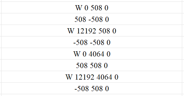
Where W represents the start point, and the line following W contains dimensions related to the previous line. All measurements are in millimeters × 10.
User Interface and Workflow
Ribbon Menu Items on Microsoft Excel Spreadsheet Template
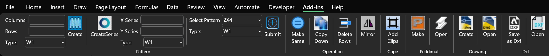
A Microsoft Excel spreadsheet with the Ribbon menu visible at the top, showing the tab Add-ins. Within the Add-ins tab related to CAD or fabrication workflows, including options like Create, Make, Add Clips, Operation, Peddimat, Dxf Save as, and Dxf Open. See the below Figure 8.
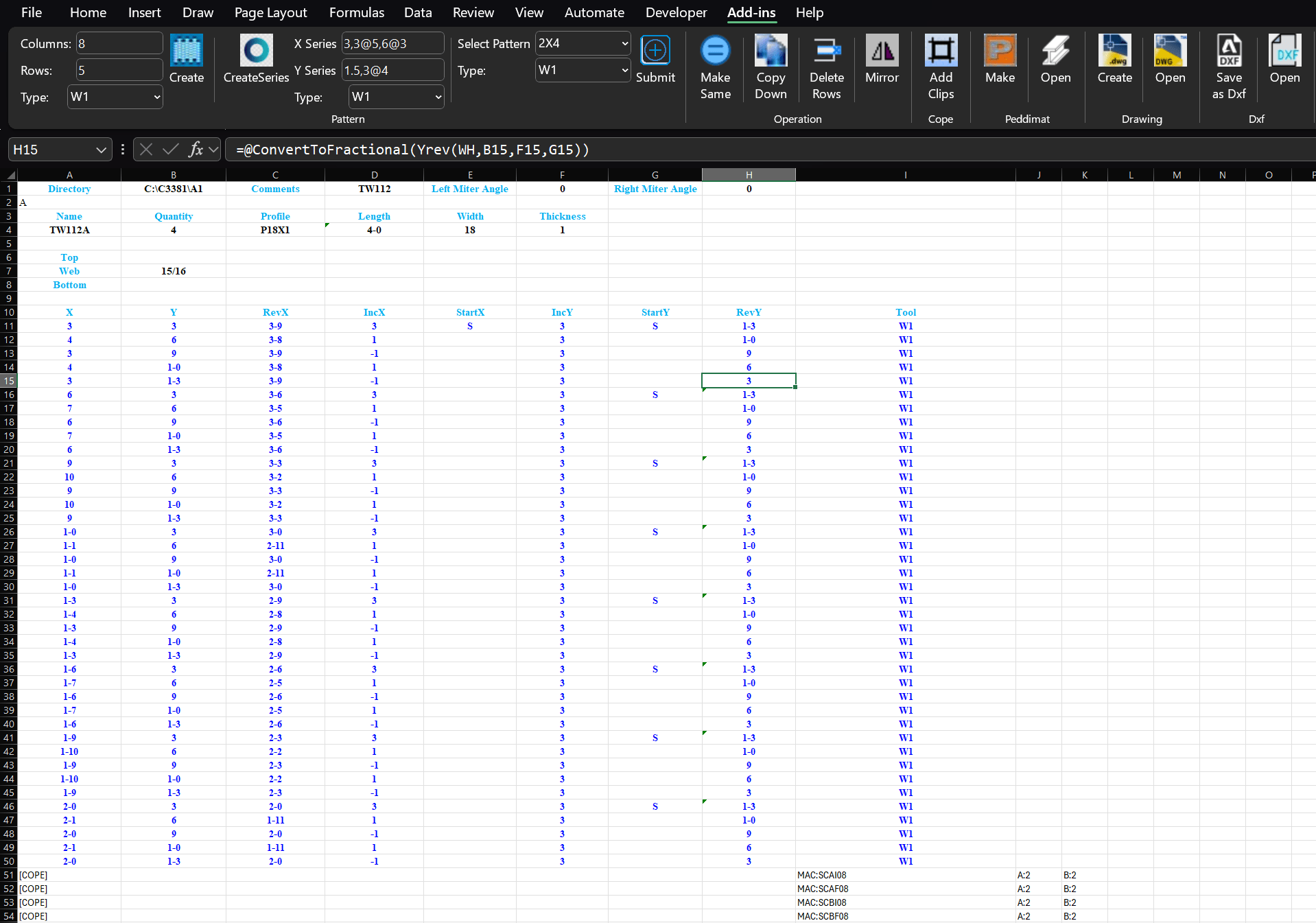
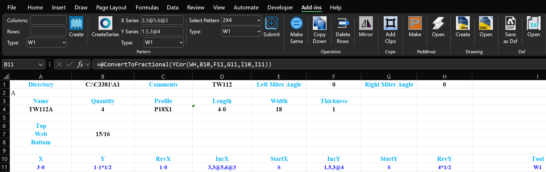
Microsoft Excel Spreadsheet Template
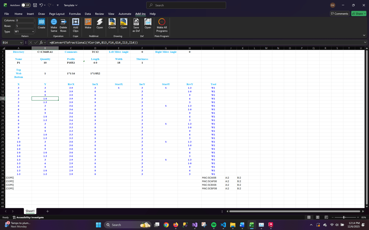
Below the Ribbon, the Excel sheet contains fabrication part data. Headers include Directory, Name, Quantity, Shape or Profile, Length, Width, Thickness, and miter angles, followed by rows listing coordinate-based drilling or burning instructions. Many rows contain values under headings such as X, Y, RevX, IncX, StartX, StartY, RevY, and Tool, with custom formulas attached to cells under those heading. Some cells display fractional dimension formats, and the formula bar shows a conversion formula used to transform coordinate values into fractional measurements. Near the bottom, several “[COPE]” entries appear along with cope names like MAC:SCAI08 and MAC:SCAF08.
Input all hole-related data using predefined patterns on ribbon text boxes and combo boxes. The formulas for X, Y, RevX, RevY and Tool are automatically generated in their respective cells. See Figure 9.
Program Creation
The application generated both a new Pedimat file and an AutoCAD Dwg file. In the Ribbon menu, enter 8in the Column text box, 5 in the Row text box, and select ‘W1’ from the Type dropdown. Click the “Create” button to generate 40 rows of hole data in the Excel spreadsheet. Adjust the IncX and IncY values as needed. Then, select the desired range and click the “Make Same” button to apply a repeating pattern for IncX (see Figure 10). Continue modifying the IncX and IncY values until the X and Y hole coordinates match those shown in the shop drawings.
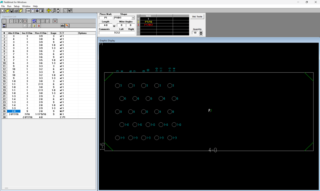
Click the “Make” button to generate the Peddimat program. To view the program, click the “Open” button. Figure 11 displays the Peddimat program that was produced.
Click “Create” button to create Dwg file and click “Open” button. The resulting Dwg file is shown in Figure 12.
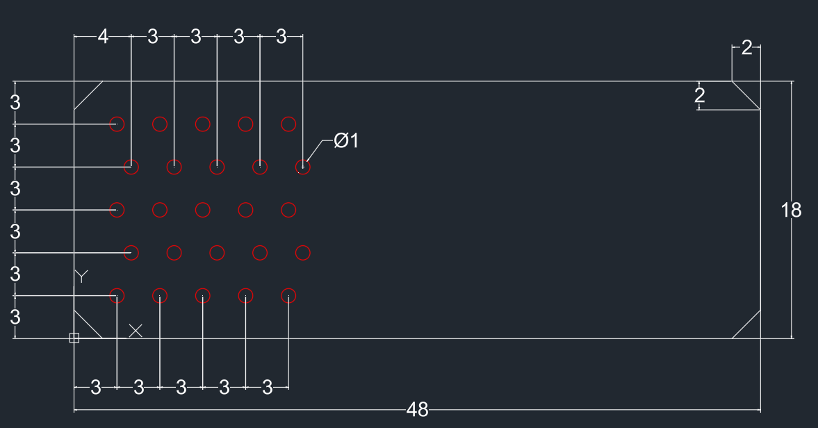
Dimensions of peddimat file and AutoCAD Dwg file are perfect match by comparing their dimensions from Figure 11 and 12.
Discussion
Comparison with Peddimat Software
Two quantitative metrics were used:
- Program Creation Time (min) – Time from data input start to create Peddimat programs for each shop drawing.
- Time Reduced (%) – Time reduced percentage per shop drawing.
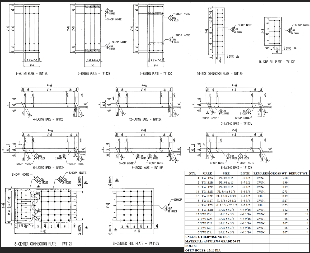
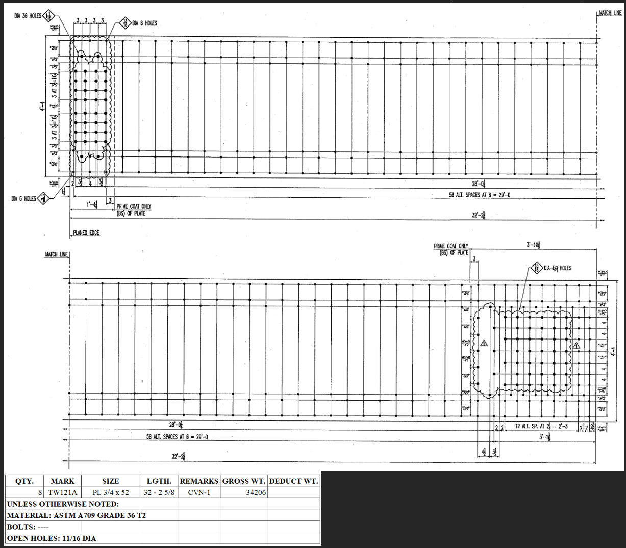
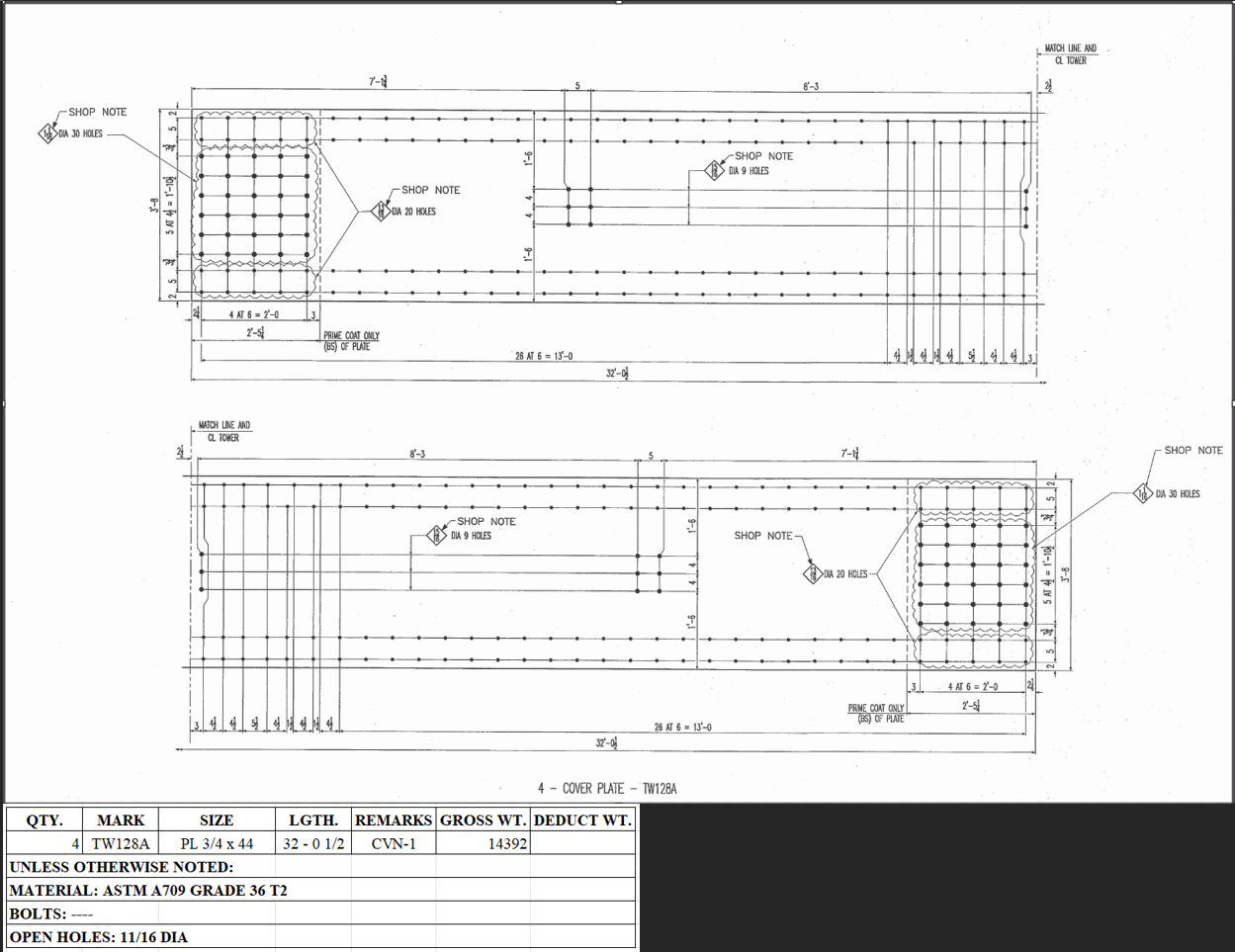
A senior programmer from a local steel fabrication company created Peddimat programs on the same Windows 11 computer using the following drawings, as shown in Figures 13 to 16.

Test results show in Table 4.
| Drawings | Time with Peddimat Software (min) | Time with the Developed App (min) | Time Reduced (%) |
| TW112 | 19 | 17 | 10.52% |
| TW113 | 3.4 | 2.7 | 20.58% |
| TW121 | 7.7 | 6.0 | 22.08% |
| TW128 | 4.2 | 3.3 | 21.43% |
Efficiency Analysis
Cell references
The developed app uses custom cell formulas that reference one another, so any change to a single value automatically updates all related cells. As a result, the X, Y, and reverse X/Y coordinates are recalculated simultaneously (see Figure 17 for explanation).
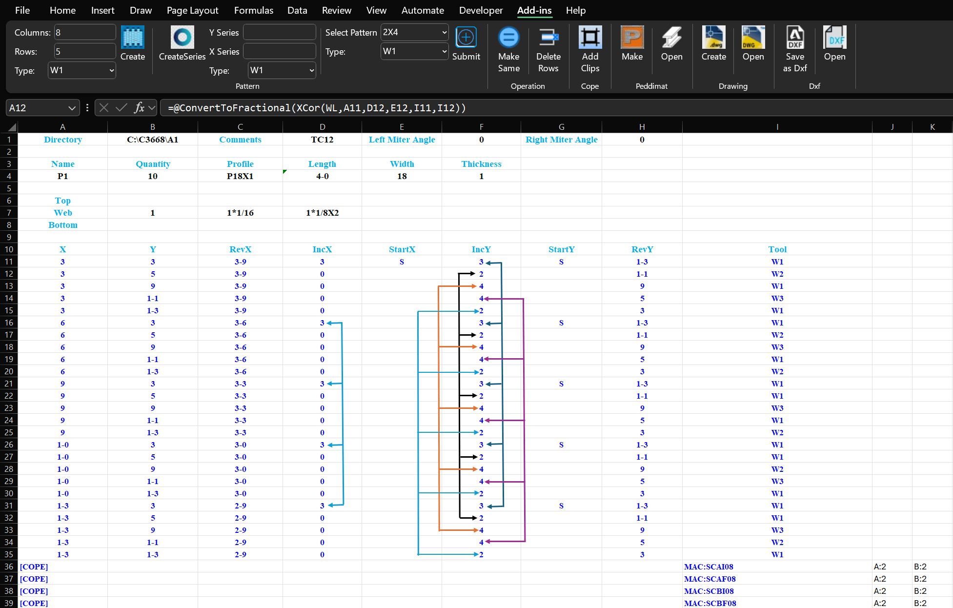
Figure 17 illustrates that the colored lines demonstrate how adjusting the value in the first cell causes the values in the following cells to update automatically. The Tool column references are like those in the IncY column.
Series Pattern
Concatenate multiple hole data lines into a single line using a series pattern, eliminating repetitive select, copy, and paste operations. See Figure 18.
Analysis
In drawing TW112, the same hole patterns (Matrix and Mirror) can be applied to piece marks TW112A through TW112C using both the Peddimat legacy software and the developed app, resulting in no time difference between the two systems. However, for TW112D and TW112F, series patterns (IncX: 1.75, 6, 4.625, 5, 5.125, 5, 4@3.3125; IncY: 2, 5) can be applied to accommodate varying horizontal spacings without line‑by‑line adjustments, making the developed app faster than the Peddimat legacy software. The programmer can also select patterns from a dropdown menu and only needs to update nine values for TW112D in the spreadsheet with reference advantages. In contrast, when modifying Abs‑X‑Dim or Inc‑X‑Dim in the Peddimat legacy software, the cursor advances hole by hole to Gage, which slows the process. The developed app avoids this step, maintaining faster performance. For piece marks TW112H through TW112R, programming utilizes series patterns and the “copy down” operation. Since the developed app eliminates the need for hole‑by‑hole adjustments, it continues to outperform the Peddimat legacy software. Additionally, when applying the Matrix pattern in Peddimat legacy software for TW112D and TW112F, both vertical and horizontal spacings must be changed manually, whereas the developed app handles these adjustments more efficiently, further increasing its speed advantage.
In drawing TW113, the varying vertical and horizontal spacings require programmers using Peddimat legacy software to perform additional manual steps—such as modifying, selecting, copying, and pasting—after applying matrix patterns. By leveraging cell reference advantages, the developed app remains faster.
In drawings TW121 and TW128, programmers can use the series patterns to define a single hole data line instead of multiple lines, unlike Peddimat legacy software. Overall, this approach significantly reduces manual operations, including frequent cursor movement.
Additionally, the spreadsheet template includes a “RevY” column, allowing programmers to verify reverse Y dimensions against shop drawings without performing lengthy manual calculations. Programmers can also configure reverse X and reverse Y coordinates for programming purposes, further reducing manual computation. Within the predefined patterns, Microsoft Excel can perform the necessary calculations and provides correct spacing increments in the cells with proper calculation, making this approach more convenient than using a calculator and the Peddimat legacy software.
Conclusions
The Peddimat program structure was successfully interpreted for the first time using Notepad++, the legacy Peddimat software (V1.08.07), and the AISC shapes database. An Excel VSTO Add-In project was developed for the first time using Visual Studio 2022, Microsoft Excel 365, and AutoCAD 2026 on Windows 11 to create both Peddimat programs and AutoCAD Dwg files.
A fluent builder interface employing a recursive design pattern was applied during development to simplify object construction, enforce consistency, and improve code readability. This approach allows complex objects to be composed step-by-step through chained method calls, while the recursive structure ensures type-safe transitions between builder stages.
Dependency Injection (DI) techniques were also implemented in the VSTO Add-In project. By injecting dependencies rather than instantiating them directly, the add-in achieves loose coupling, enhanced maintainability, and improved testability. Additionally, PlantUML combined with Visual Studio Code was used to generate design architecture diagrams.
Several .NET Framework class libraries were developed to support modular functionality:
- CustomFormula: Implements custom formulas (UDFs) that users can apply directly within Excel spreadsheets.
- FracDecConverter: Provides shared unit conversion functionalities for all projects, reducing redundant code.
- PeddimatCopesLib: Enables efficient addition of clips to Peddimat programs and facilitates the creation of AutoCAD Dwg files.
An Excel spreadsheet template was developed to enable users to input hole data and specify hole types using predefined or dynamic patterns. The template offers a user-friendly interface, and the resulting data can be used to generate both Peddimat programs and AutoCAD DWG files.
A comparison of efficiency between the legacy Peddimat software and the developed app demonstrates that creating Peddimat programs with the developed app is more faster. Around 20% reduction based on test cases in program creation time Furthermore, verifying Peddimat programs with the developed app is considerably easier compared to using the legacy software, and AutoCAD Dwg files can be quickly converted to Dxf files for other Peddinghaus plate processors. Peddimat files are specific to the Peddinguase machine. Future work should focus on how to create DSTV files for most of fabricator machines.
References
- M. Srinivas, G. Ramakrishna, K. R. Rao, E. S. Babu. Analysis of legacy system in software application development: a comparative survey. International Journal of Electrical and Computer Engineering. Vol. 6, pg. 292-297, 2016, http://doi.org/10.11591/ijece.v6i1.pp292-297. [↩]
- S. Zhang, J. Bai. Research on CNC programming and machining process based on CAD/CAM technology. Applied Mathematics and Nonlinear Sciences. Vol. 9, pg. 1-18, 2024, https://doi.org/10.2478/amns-2024-0516. [↩]
- N. Thakur1, E. A. Gupta. Automation of design process using Etabs, Microsoft Excel and AutoCAD. IOSR Journal of Mechanical and Civil Engineering. Vol. 14, pg. 50-62, 2017. [↩]
- W. Xiao, L. Zheng, J. Huan, P. Lei. A complete CAD/CAM/CNC solution for STEP-compliant manufacturing. Robotics and Computer-Integrated Manufacturing. Vol. 31, pg. 1-10, 2015, https://doi.org/10.1016/j.rcim.2014.06.003. [↩]
- X. Xu, Q. He. Striving for a total integration of CAD, CAPP, CAM and CNC. Robotics and Computer-Integrated Manufacturing. Vo1. 20, pg. 101-109, 2004, https://doi.org/10.1016/j.rcim.2003.08.003. [↩]
- S. Omirou, M. Charalambides, A. Lontos, M. Menicou, G. Demosthenous. A dedicated CAD/CAM module for high precision CNC milling of complex threads. The International Journal of Advanced Manufacturing Technology. Vol. 140, pg. 2195–2210, 2025, https://doi.org/10.1007/s00170-024-13970-5. [↩]
- M. Simonič, I. Palčič, S. Klančnik. Advancing intelligent toolpath generation: a systematic review of CAD–CAM integration in industry 4.0 and 5.0. Strojniški vestnik – Journal of Mechanical Engineering. Vol. 71, pg. 328-336, 2025, https://doi.org/10.5545/sv-jme.2025.1370. [↩]
- L. Kirner, V. Jung, J. Oraskari, and S. Brell-Cokcan. Enhancing robotic steel prefabrication with semantic digital twins driven by established industry standards. Automation in Construction. Vol. 167, 2024, https://doi.org/10.1016/j.autcon.2024.105699. [↩]
- X. Zhao and Y. Chung. Development of a robotic structural steel cutting system. IOP Conference Series: Materials Science and Engineering. Vol. 538, 2019, https://doi.org/10.1088/1757-899X/538/1/012042. [↩]
- T. B. Elserwy, T. Aly, B. E. El-Demerdash. End-user software engineering approach: improve spreadsheets capabilities using Python-based user-defined functions. Indonesian Journal of Electrical Engineering and Computer Science. Vol. 38, pg. 1024-1032, 2025, https://doi.org/10.11591/ijeecs.v38.i2.pp1024-1032. [↩]
- E. Carter and E. Lippert. Visual Studio tools for Office 2007: VSTO for Excel, Word, and Outlook. Vol. 1–2, 2007. [↩]
- T. Chen, Y. Ren, G. Xie, F. Liu, K. Luo. Comparative study on secondary development methods of AutoCAD: performance comparison and application of C#, VB, and ObjectARX. Journal of Computer Science and Artificial Intelligence. Vol. 2, pg. 77-83, 2025, https://doi.org/10.54097/adpthn55. [↩]
- X. Chen. Research on the application of CAD technology in mechanical drawing. China Equipment Engineering. Vol. 17, pg. 241-244, 2023. [↩]
- M. Seidl, M. Scholz, C. Huemer, G. Kappel. UML @ classroom: an introduction to object-oriented modeling. Springer, 2015, https://doi.org/10.1007/978‑3‑319‑12742‑2. [↩]
- PlantUML, PlantUML language reference guide. https://pdf.plantuml.net/PlantUML_Language_Reference_Guide_en.pdf. 2025. [↩]
- M. Chadwick. Design patterns in .NET 6: reusable approaches in C# and F# for object-oriented software design. Apress, 2022, https://doi.org/10.1007/978-1-4842-8245-8. [↩]
- S. V. Deursen, M. Seemann. Dependency injection principles, practices, and patterns. Manning, 2019. [↩]
- P. Michaels. Software architecture by example: using C# and .NET. Apress, 2022, https://doi.org/10.1007/978-1-4842-7990-8. [↩]
- A. Troelsen, P. Japikse. Pro C# 10 with .NET 6: foundational principles and practices in programming. Apress, 2022, https://doi.org/10.1007/978‑1‑4842‑7869‑7. [↩]
- B. Kramer. ObjectARX primer (Autodesk’s programmer series). Autodesk Press, 2000. [↩]
- J. A. Leach, S. Lockhart. AutoCAD 2026 instructor: a student guide for in-depth coverage of AutoCAD’s commands and features. SDC Publications, 2025. [↩]


