
Abstract
This study investigates the optimization of micro scale wind turbine blades for portable generators by utilizing 3D printing technology. Portable wind turbines are valuable for harvesting renewable energy in remote areas or off-grid situations. However, the designs, particularly for low wind speed circumstances, have not been thoroughly explored. In this research paper, a home-built portable generator with 3D-printed blades was used to examine blade design optimization. The power generated at the wind speeds of 3-4 m/s was measured using a simple circuit equipped with multimeters. Various configurations, from straight, curved, to twisted were printed and tested. Notably, the twisted blades increased the power outputs. The design parameters, such as the twisted angle, blade length, width at different positions (base, tip, peak), the number of blades, and weight, were analyzed to determine their effect on power generation. Through the study, the blade geometry was optimized, resulting in over 40% increase in power output from a simple straight configuration. The use of 3D printing enabled quick and precise modifications of blade geometry even with complex geometry, which led to improved efficiency. In addition, a flexible base was incorporated to enhance the blades’ ability to operate effectively at low wind speeds, which indicates the needs for variable angles. Overall, this exercise demonstrates that 3D-printing is a viable tool for the portable wind turbine design, which needs further development. The optimized turbines could be commercially feasible for manufacturing to meet the flexible demand for renewable energy for in areas with limited or no access to the electrical grid.
Keywords: 3D Printing, Wind Turbine, Optimization
Introduction
As the world continues to seek renewable energy sources to address the climate crisis posed by Green House Gas (GHG), wind power has been one of most promising solutions picking up the slack on the power grid. Ever since its first implementation in an electricity generating application by Professor James Blyth in July of 18871, horizontal axis wind turbines2 have seen significant improvements in efficiency, and total power generation. Wind power now makes up over 10% of all US electricity generation3.
Despite all these advances, there are still hurdles such as high initial manufacture cost for wind power development. In addition, the small-scale applications have not received enough attention for optimization4. Traditional Horizontal Axis Wind Turbines are economically not viable to scale down for portable applications due to the cost of manufacture5, while Vertical Axis Wind Turbines are less the efficient than Horizontal Axis Wind Turbines.
The emergence of 3D printing has provided many new manufacturing opportunities that had previously not been available. Files created in computer aided design (CAD) software can now be directly manufactured, without the need for the creation of expensive tooling and production lines. Additionally, this has also made it possible for normally prohibitively complex geometries to be created without difficulties, and many more geometries to be tested cost-effectively. Given the complex nature of wind turbine blade geometry, 3D printing is an excellent technology to explore for the manufacture of wind turbine blades6‘7‘8.
Traditional commercial scale wind turbines have the rotor diameter larger than 10 meters. These blades are made of fiberglass composites, which is difficult to recycle once blades are past their service life9. The small-scale wind turbines typically can be subdivided further into micro, mini and household size wind turbines with size range from 0.5 – 1.25 meter, 1.25 – 3 meters 3 – 10 meters accordingly with wind speed range between 10 -100 km/h. Certainly, the power output significantly depends on the turbine size. With a range of .01 to 10kw power outputs, it can a good supplemental electricity to a typical U.S. home. These small-scale blades can be 3D printed with polymers have been studied10‘11. With further reductions of blade size to ultra-micro scale, higher wind speeds are needed to keep power output12. Maximizing the power generation, which is directly correlated with rotational speed, is more critical than power conversion efficiency. This study focuses on the optimization of the wind turbine blade design by 3D printing technology to maximizing the power generation at low wind speeds. Certainly, the power output is determined by voltage and current and affected by the type of electrical element. Simple voltage measurement is a quick way to compare the efficiency of the blade design. An ultra-micro-scale wind power setup was home-built based on 3D printed horizontal blade with a 3 Volt DC motor. This setup helped to screen the wind blade geometry efficiently at three low wind speeds. The optimized geometry made an over 40% increase in power output than the initial simple straight blade. The study showed 3D printing is a cost-effective way to optimize and manufacture the portable size wind turbine. With modification of the motor in the future, this light weighted, small, portable and easy-to-made wind generator can be carried easily while travelling to get necessary electric power at the time of need. The generated electric power can be stored in a battery or power bank through which various electronic apparatus like mobile phones, torch light etc. can be charged simultaneously or later.
Results
The study went through 3 stages while optimizing the blade designs. The data are summarized in Tables 1, 2 and 3. The voltage over the DC motor was measured and later converted to power output with a 10-ohm resistance circuit.
Blade Design
The construction parameters started with simple straight designs as shown in Table 1. While 3-blade wind turbines are more popular for commercial applications for better aerodynamic balance and higher energy capture efficiency, 2-blade turbines are easier to maintain and manufacture with a lower cost. More importantly, 2-blade turbines can reach higher rotational speed, which is more suitable for portable applications, which was the reason a two-blade design was utilized in the initial stage. The turbine was tested at the highest fan wind speed (3.98 m/s). Certainly, 3- and 4-blade configurations were tested as well to confirm the theory, and the results are listed in Table 2.
| Run | Blade Design | Leader Edge Shape | Blade Length (cm) | Base Chord Length(cm) | Peak Chord Length Position from Base (cm) | Peak Chord Length (cm) | Tip Chord Length (cm) | Angle at Tip Chord (degree) | Angle at Base Chord (degree) | Power Output, mW, at High Wind Speed | Efficiency |
| 1 | A | straight | 9.250 | 3.5 | 0 | 3.5 | 1.75 | 10 | 10 | 28.1 | 4.7% |
| 2 | B | straight | 9.250 | 4.0 | 0 | 4.0 | 1.75 | 10 | 10 | 28.2 | 4.8% |
| 3 | C | straight | 9.250 | 4.0 | 0 | 4.0 | 2.00 | 10 | 10 | 28.4 | 4.8% |
| 4 | D | straight | 9.250 | 4.0 | 0 | 4.0 | 3.00 | 10 | 10 | 27.7 | 4.7% |
| 5 | E | twisted | 9.250 | 0.5 | 4 | 3.5 | 2.00 | 10 | 10 | 29.0 | 4.9% |
| 6 | F | twisted | 9.250 | 1.2 | 4 | 3.5 | 2.00 | 5 | 10 | 33.9 | 5.7% |


CD

CD
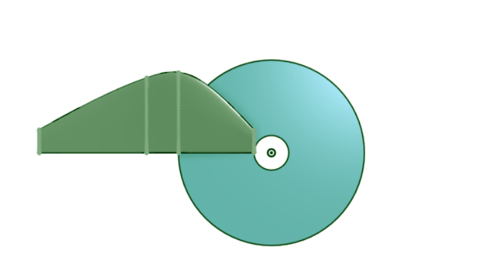
To achieve higher power outputs, development began with blade geometry with a peak air-foil length at the base of the blade, as shown by Figure 1a and 1b. The widest point of the blade was situated over the attachment point to the disk (4 cm), as shown in Figure 1c. It was found that blades with geometry that situated the peak chord length of the airfoil outside of the disk would provide significantly increased rotational rate and therefore power generation. Additionally, it was found that a decrease in angle of attack of the blade closer to the tip would also increase performance significantly, hence the “twisted” blade design.”
Variations in the weight of the blades were ignored as they are negligible, constituting a change of a few tens of milligrams in an already extremely light blade. Certainly, it needs to be considered for practical applications, but was considered a secondary factor here.
Screening of Blade Parameters
After step 1, where a twisted design was proved to be the best, more blades with modified geometries were 3-D printed and the subsequent performance was measured. The blades were assembled into different turbines, each blade geometry having a 2-blade, 3-blade, or 4-blade variants. Each of these variants were then tested at three wind speeds, and the power output was obtained with the measured voltages. The characteristics of these turbines are given in Table 2 below along with the recorded power outputs for run 7 to 15.
| Run | Blade Design | Leader Edge Shape | # of Blade | Blade Length (cm) | Base Chord Length (cm) | Peak Chord Length Position from Base (cm) | Peak Chord Length (cm) | Tip Chord Length (cm) | Angle at Tip Chord (degree) | Angle at Base Chord (degree) | Power Output, mW, at High Wind Speed | Power Output, mW, at Medium Wind Speed | Power Output, mW, at Low Wind Speed | Efficiency at High Wind Speed |
| 7 | G | twisted | 2 | 10.375 | 1.0 | 4 | 3.5 | 1.00 | 2.5 | 7.5 | 35.2 | 29.3 | 22.1 | 5.9% |
| 8 | 3 | 31.1 | 26.0 | 20.3 | 5.3% | |||||||||
| 9 | 4 | 27.5 | 23.6 | 18.4 | 4.6% | |||||||||
| 10 | H | twisted | 2 | 9.250 | 1.0 | 4 | 3.5 | 0.50 | 5.0 | 10.0 | 35.9 | 29.2 | 22.1 | 6.1% |
| 11 | 3 | 32.1 | 26.1 | 20.5 | 5.4% | |||||||||
| 12 | 4 | 28.0 | 24.0 | 18.5 | 4.7% | |||||||||
| 13 | I | twisted | 2 | 10.375 | 1.0 | 4 | 3.5 | 1.00 | 5.0 | 10.0 | 35.9 | 29.1 | 22.1 | 6.1% |
| 14 | 3 | 33.1 | 26.8 | 21.1 | 5.6% | |||||||||
| 15 | 4 | 28.8 | 24.3 | 18.6 | 4.9% |
Turbines constructed with 2 blades generated the highest power with all three wind speeds, and the 4-blade design yielded the lowest voltage. Therefore, the study focused on 2-blade designed for further optimization in step 3 and the results are listed in Table 3. When the blade length was increased to 10.375cm, the higher base angle blade geometry, design ‘I’ produced consistently higher voltages compared to design G as shown in Table 2. When the blade length was changed to 9.25, the power out was seen to further increase. It was also determined that a base pitch angle of 7.5 degrees produced higher power than 10 degrees with 9.25 cm the blade length as demonstrated by run 16 and 17.
| Run | Leader Edge Shape | Blade Length (cm) | Base Chord Length (cm) | Peak Chord Length Position from Base (cm) | Peak Chord Length (cm) | Tip Chord Length (cm) | Angle at Tip Chord (degree) | Angle at Base Chord (degree) | Power Output, mW, at High Wind Speed | Power Output, mW, at Medium Wind Speed | Power Output, mW, at Low Wind Speed | Efficiency | |
| 16 | J | twisted | 9.250 | 1.0 | 4 | 3.5 | 1.00 | 5.0 | 10.0 | 36.3 | 29.3 | 22.0 | 6.1% |
| 17 | K | twisted | 9.250 | 1.0 | 4 | 3.0 | 1.00 | 5.0 | 10.0 | 37.0 | 29.5 | 22.1 | 6.3% |
| 18 | L | twisted | 9.250 | 1.0 | 4 | 3.5 | 1.00 | 2.5 | 7.5 | 38.2 | 31.0 | 23.2 | 6.5% |
| 19 | M | twisted | 9.250 | 1.0 | 4 | 3.0 | 1.00 | 3.5 | 8.5 | 38.7 | 30.0 | 22.1 | 6.5% |
| 20 | N | twisted | 9.250 | 1.0 | 4 | 3.0 | 1.00 | 2.5 | 7.5 | 39.7 | 30.5 | 22.1 | 6.7% |
Finally, it can be determined that blades with a maximum chord length of 3 cm produce higher maximum power compared to those with a maximum chord length of 3.5 cm. This is shown when Blade Type K and Blade Type J are compared. For all blade numbers and wind speeds, Blade Type K produced a higher power.
The blade was future optimized based on the following these tests as data collected in Table 3. Blades M and N reached 38.7 mW and 39.7 mW respectively at the highest wind speed as shown in Table 3. The efficiency was calculated as 6.5 and 6.7% respectively, which is over 40% higher than design A, which is only 4.7%.
Modification for Adapting to Low Wind Speed
During the tests, it was found that when the wind speed is lower than 0.01 m/s, the turbine would not start to rotate with the fixed angle, which was optimized for the higher wind speed. To make it work at various wind speeds, the blades were glued to the CD with a spring-like 3-D printed connector 3-D printed from Thermoplastic Urethane (TPU) as shown in Figure 1d, which keeps the blade at a high initial angle at low speed, and the angle will decrease under pressure when a high wind speed to achieve an optimal angle for power generation. Certainly, the variable angle adds flexibility to the design but can further complicate the manufacturing process. It needs to further examined depending on the application scenarios.
Discussion
The two main forces that determine the maximum generated rotational speed, and subsequently power outputs, are the lift and drag forces on the blades of the wind turbine as speed changes. These two forces are also influenced by a variety of parameters.
The drag generated by the blades is determined by two other factors: the cross section of the blade perpendicular to the tangential velocity of the blades, and the square of the tangential velocity of the blades relative to the airflow. As the cross section of the blade relative to the tangential velocity is static, the only factor that affects the drag as rotational rate increases is the tangential velocity of the blades. As the rotational rate of the blades increases, the tangential velocity of the blades similarly increases. Due to the increase in tangential velocity as the radius of a rotation object increases, the tips of the blades will experience significantly more drag compared to areas in the middle or the base of the blades.
The lift forces of the blades are determined by a multitude of factors, the most important of which is the angle of attack of the blade relative to the airflow, and the surface area of the blade parallel to the airflow. As the rotational speed of the turbine increases, the angle of attack of the blades decreases, as the component generated by the tangent velocity of the blade increases. This decreases the amount of lift generated by the wind turbine blade.
These two factors combined determine the optimal point at which the wind turbine generates the highest rotational rate or efficiency to convert wind to electricity, as the increasing drag forces and decreasing lift forces eventually reach an equilibrium, where no acceleration is possible.
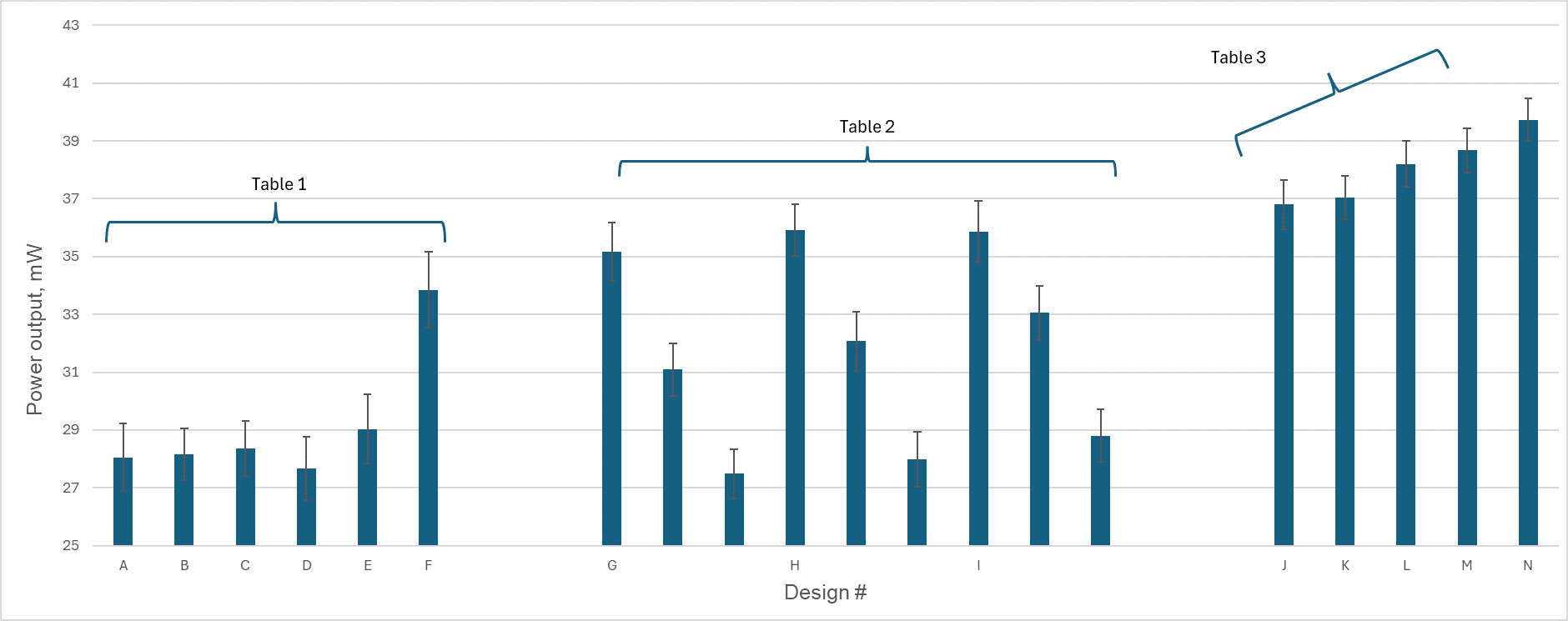
The number of blades have the most impact on power generation assuming the blades remain the same. With additional blades, it reduces the cross-section for air to pass through the turbine and thus increases drag. Each turbine blade creates turbulence behind its path of rotation, and as more blades are attached to the turbine, the amount of lift generated by each additional blade diminishes, while the drag created increases. For this application, 2 blades are the optimal count for a balanced wind turbine. However, for applications where torque is a significant design consideration, more blades may be more suitable. This can be seen in Figure 2, Table 2, as the designs with a higher blade count shows a consistent downwards trend.
Besides the clear connection between voltage generation and the number of blades, the blade pitch and length are more complicated to optimize. The optimal blade pitch is largely dependent on the rotational speed of the turbine, which is affected by the blade length. Due to the drag exerted on the turbine being proportional to the square of the tangential velocity velocity13, the doubling of the length of a wind turbine blade, and therefore the tangential velocity at the tips of the blades, is met with four times increase in the drag of the turbine. This explains that a higher pitch angle is better for a longer turbine blade, as more lift is required to overcome the increased drag created by the turbine blade.
The same seems to apply for the changes in wind speed. A decrease in wind speed means a decrease in lift generated by the blades for two reasons. First is that the angle of airflow relative to the blades strays away from the optimal angle of attack. Secondly, the decreased velocity of the speed inherently generates less lift, as lift is proportional to surface area, air density, and velocity squared.
At low wind speed, the surface area of the blade must be increased to maximize the lift force, by either longer blades, larger chord diameters, or a higher angle of the blade relative to the plane of rotation.
The variation in weight is mainly due to the design of the blade geometry. The longer blades, with larger maximum chord diameters would inevitably require more material. Blades with more mass have a higher rotational inertia requiring more force to accelerate to speed, reducing the maximum rotational rate, resulting in a lower maximum power output.
Some of the variations in blade weight with the same geometry can be caused by the manufacturing process. The material that is utilized obtains its low density through foaming: the material creates air bubbles within itself when it is extruded through the nozzle of the printer. This process is inherently random, as the air bubbles vary in size depending on many factors such as humidity, temperature, extrusion rate, and so many more. This is certainly a factor that must be considered especially for larger blade design. However, in this application, the same blade geometry produces the blade weight within 1% error. The power outputs from two blades vs single blade weight are plotted in the Figure 3. For the similar design, the increasing weight leads to lower power outputs. However, at similar weight, the blade geometry significantly impacts the output.

However, the biggest cause of the variation in blade weight is the surface area of the blade. Since the blades are created in such a way that they are entirely hollow, with a uniform surface thickness, an increased surface area will increase the amount of material used, and therefore the weight. The weight is more so a measurement of the surface area of the blade, rather than the weight having any significant effect on the blade.
Methods
Materials
Polylactic Acid-Aero (PLA-Aero) Filament
PLA-Aero filament was purchased from BambuLab. This material was chosen for its compatibility with hobby-grade 3D printers. In addition, the “Aero” grade can generate a density 20%-50% lower than a standard PLA.
Thermoplastic Urethane (TPU) filament
TPU filament was purchased from BambuLab. This TPU material has outstanding impact resistance and flexibility, so it is used to make the connection between CD and turbine.
MiniDVD
MiniDVD was purchased from Amazon as a mounting base for wind turbine blades. The MiniDavd has a reduced surface area compared to standard sized DVDs, allowing for more of the blade to operate without the hinderance of the disk behind it.
Poly-Cyanoacrylate Glue
It was purchased from local Craft Store. This was used to bond the blades to the disk. The dosage applied to each blade was controlled to make sure the weight consistent within 1% error range.
Equipment
Bambu Lab A1 3D printer was used to produce the blades. The printer was equipped with a 0.2mm nozzle, to minimize the skin width of the blades. Onshape Computer Aided Design software was used to design the blade geometry.
BambuSlicer software was used to convert the blade geometry into manufacturing instructions for the 3D Printer. All blades were constructed using the same print settings for consistency, with 0.2 millimeter walls and zero infill.
ACU RITE Portable Anemometer (Model 00256) was used to measure the wind speed.
Lasko Box Fan was used to produce wind. The wind speeds at measured distances (10 cm) are 2.95 m/s, 3.40 m/s and 3.98 m/s respectively for low, medium and high settings.
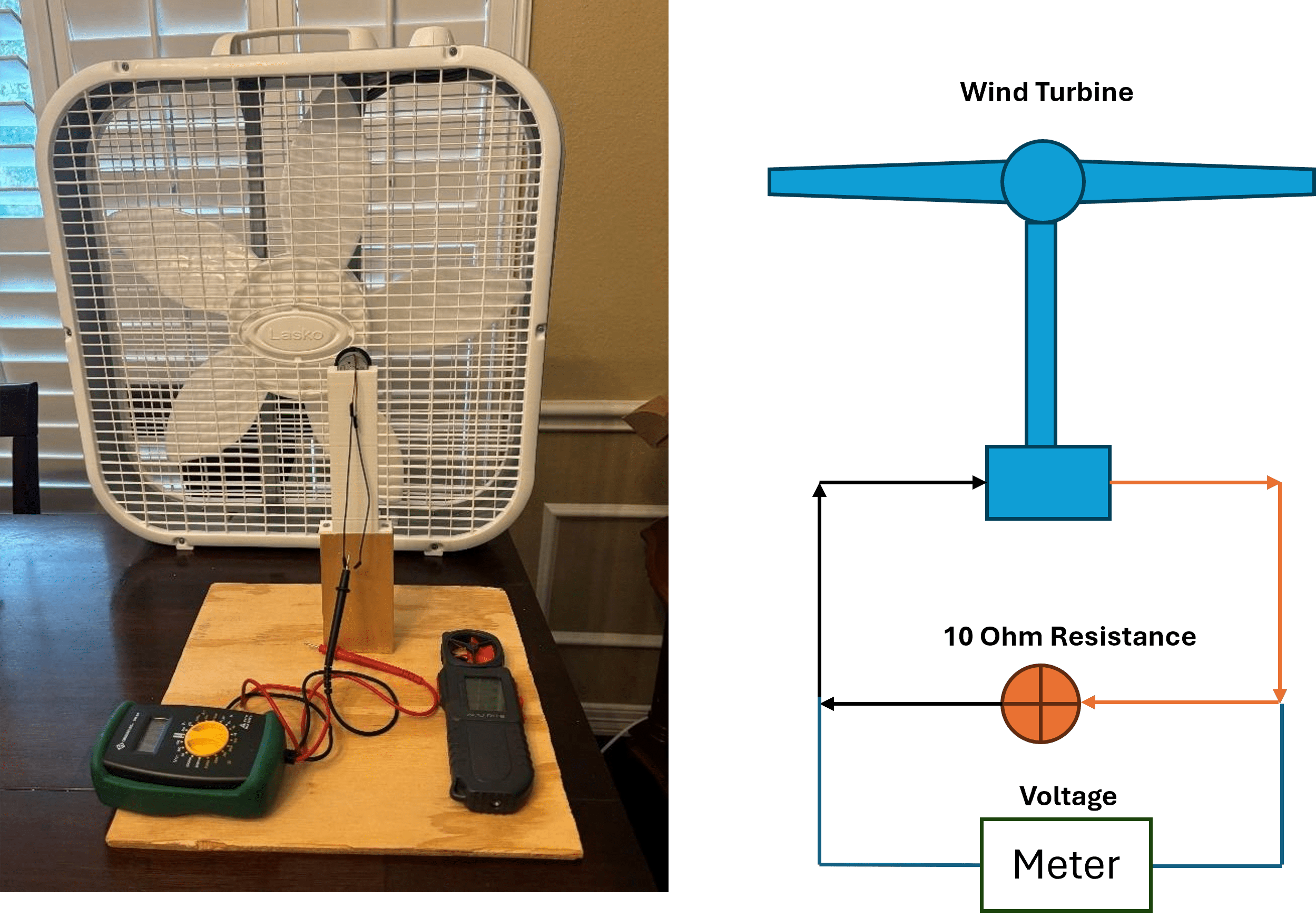
GREENLEE Multimeter (Model DM-20) was used to measure the voltage and current. A 10-ohm resistance was introduced in the circuit to measure the power outs as shown in Figure 4. By measuring the voltage cross the resistance, the power consumption can be calculated.
3 Volt DC Motor (Model RF-300CA-11400-R) was connected with the turbine blades for electricity generation.
Testing Setup
The test setup consisted of a standard Box fan, and a 3D-printed mount for the DC motor, which is attached to a Plywood board. The DC motor is then linked to a multimeter, which is used to measure output voltage and amperage. The setup is shown in the Figure 4. Detailed blade design is shown in Figure 5.

Test Procedure
Manufactured wind turbines were first attached to the testing rig. The turbine rig was positioned in a fixed position (10 cm) away from the front face of the box fan. A box fan of this type produces turbulent airflow, but it is assumed that this mimics the condition in reality and is a good way to test the turbine efficiency. Then the fan was set to the selected speed setting. The turbine was allowed to run to its maximum rotational rate. The turbine was manually initiated if it was unable to begin rotating on its own at low wind speed. The maximum voltage was recorded for the specific turbine at a specific wind speed. This “Maximum Voltage” means the highest displayed voltage of a period of roughly 30 seconds once the turbine has accelerated to its operating speed. All relevant data was collected in an air-conditioned room to avoid issues regarding changes in air density, humidity, temperature, and other external factors.
Conclusion
Through the data collected in this paper, it is concluded that higher power is generated if the drag force induced on the blade is minimized, and the lift force is maximized. This can be accomplished by reducing the angle of attack of the blade to the wind, but there are other optimizations that can also be made. In addition, this demonstrates the feasibility of 3d printing wind turbine geometries for prototyping, and even possibly constructing blades on a small scale with more advanced materials like Carbon Fiber infused Polycarbonate. The type of materials and higher wind speed should be investigated in future studies.
References
- J. Blyth. On the application of wind power to the generation and storage of electricity. Proceedings of the Philosophical Society of Glasgow. 5 (2), 1-2 (1888). [↩]
- S. E. Mouhsine, K. Oukassou, M. M. Icheninal, B. Kharbouch, A. Hajraoui. Aerodynamics and structural analysis of wind turbine blade. Procedia Manufacturing. 22, 747-756 (2018). [↩]
- U.S. Energy Information Administration, https://www.eia.gov/tools/faqs/faq.php?id=427&t=3 (2023). [↩]
- A. Tummala, R. K. Velamati, D. K. Sinha, V. Indraja, V. H. Krishna. A review on small scale wind turbines. Renewable and Sustainable Energy Reviews. 56, 1351-1371 (2016). [↩]
- M. A. Rawajfeh, M. R. Gomaa. Comparison between horizontal and vertical axis wind turbine. International Journal of Applied Power Engineering (IJAPE). 12(1), 13-23 (2023). [↩]
- S. C. Ligon, R. Liska, J. Stampfl, M. Gurr, R. Muhaupt. Polymers for 3D printing and customized additive manufacturing. Chemical Reviews. 117, 10212-10290 (2017). [↩]
- A. K. Zarzoor, A. A. Jaber, A. A. Shandookh. 3D printing for wind turbine blade manufacturing: a review of materials design optimization, and challenges. Engineering and Technology Journal. 42, 895-911 (2024). [↩]
- B. P. Conner, G. P. Manogharan, A. N. Martof, L. M. Rodomsky, C. M. Rodomsky, D. C. Jordan, J. W. Limperos. Making sense of 3D printing: creating a map of additive manufacturing products and services. Additive Manufacturing. 1, 64-76 (2014). [↩]
- S. Zhang, N. Kirumira. Techniques of recycling end-of-life wind turbine blades in the pavement industry: a literature review. Clean Technologies and Recycling. 4 (1), 89-107 (2024). [↩]
- A. Suresh, K. S. Raja, A. Belqasem, B. T. Sudhakar. Investigation of performance of 3D printed micro wind turbine composed of PLA material. Heliyon 10, e25356 (2024). [↩]
- R. A. Kishore, T. Coudron, S. Priya, Small-scale wind energy portable turbine (SWEPT). Journal of Wind Engineering and Industrial Aerodynamics. 116, 21-31 (2013). [↩]
- M. Z. Hossain, S. M. A. Rahman, M. I. Hasan, M. R. Ullah, I. M. Siddique. Evaluating the effectiveness of a portable wind generator that produces electricity using wind flow from moving vehicles. Journal of Industrial Mechanics. 8, 2582-1067 (2023). [↩]
- J. Anderson, Fundamentals of Aerodynamics. McGraw-Hill, 6th edn. [↩]


