
Abstract
Rear spoilers must balance aerodynamic efficiency with structural resilience. This study evaluates a fixed-geometry spoiler manufactured from ABS, aluminum 6061-T6, and quasi-isotropic CFRP using finite-element analysis under three representative pressure loads (520, 1 040, and 1 560 Pa) derived from dynamic pressure estimates. Aluminum demonstrated the smallest tip deflections (0.054–0.162 mm) with consistently high safety margins (SF ≥ 7.3 at 1 560 Pa). CFRP provided similarly low deflections (0.165–0.495 mm), with adequate safety (SF ≥ 4.85). When normalized by mass, aluminum exhibited the best static stiffness-to-mass (smallest ∆/ρ), while CFRP achieved the best dynamic stiffness-to-mass (largest f1/ρ). By contrast, ABS exhibited substantial deformation (1.82–5.45 mm) and dropped below unity safety at the highest loading condition (SF ≤ 0.96), indicating failure onset. The first-mode natural frequencies were approximately 25.7 Hz for aluminum, 21.6 Hz for CFRP, and 7.26 Hz for ABS, with the ABS mode falling far short of the 30 Hz vibration-resistance target and thus disqualifying it as a viable material choice for this geometry. Overall, the results indicate aluminum is preferred when minimizing deflection or maximizing static stiffness-per-mass, CFRP is advantageous where mass reduction and dynamic stiffness-per-mass are prioritized, and ABS is unsuitable for structurally loaded spoilers.
Introduction
Automotive rear spoilers generate down-force that enhances vehicle stability at high speeds. In high performance vehicles, rear spoilers improve track performance and vehicle control. As the automotive industry improves efficiency, moving towards more lightweight designs, the use of advanced composites in spoilers becomes necessary. While previous studies have emphasized aerodynamic design assessment of spoiler profiles, relatively fewer have evaluated how structural materials affect performance metrics. This is especially the case with the invention of advanced composites. Testing advanced composites is crucial to understand how these materials can be used for improvements in the automotive industry. For fixed geometry, the stiffness-to-weight characteristics of the material dictate deformation, stress distribution, and fatigue life.
Background
Foundational studies on road-vehicle aerodynamics and spoiler effects provide the context for this work, including canonical wake investigations and spoiler aeroelasticity analyses1,2.
For spoilers with fixed geometry, material selection becomes the primary driver of mechanical behavior. The choice of material influences both structural stiffness and deflection. As automotive manufacturers strive to reduce vehicle weight without compromising performance or safety, understanding how different materials respond to aerodynamic forces becomes essential. Finite Element Analysis (FEA) offers a noninvasive approach to evaluate and isolate the mechanical response of materials, making it the ideal methodology for this comparative research study.
This work therefore addresses the following research question: How does material choice influence deflection, stress, and safety factor for a fixed spoiler geometry under realistic aero- dynamic loading? We evaluate three materials widely used in automotive body-exterior ap- plications—ABS, Aluminum 6061-T6, and quasi-isotropic CFRP3,4. To answer this research question, we begin from an open-source geometry of a spoiler that allows us to perform a structural analysis. This study establishes baseline performance for the spoiler using various materials under loading conditions.
Methods
Spoiler Geometry
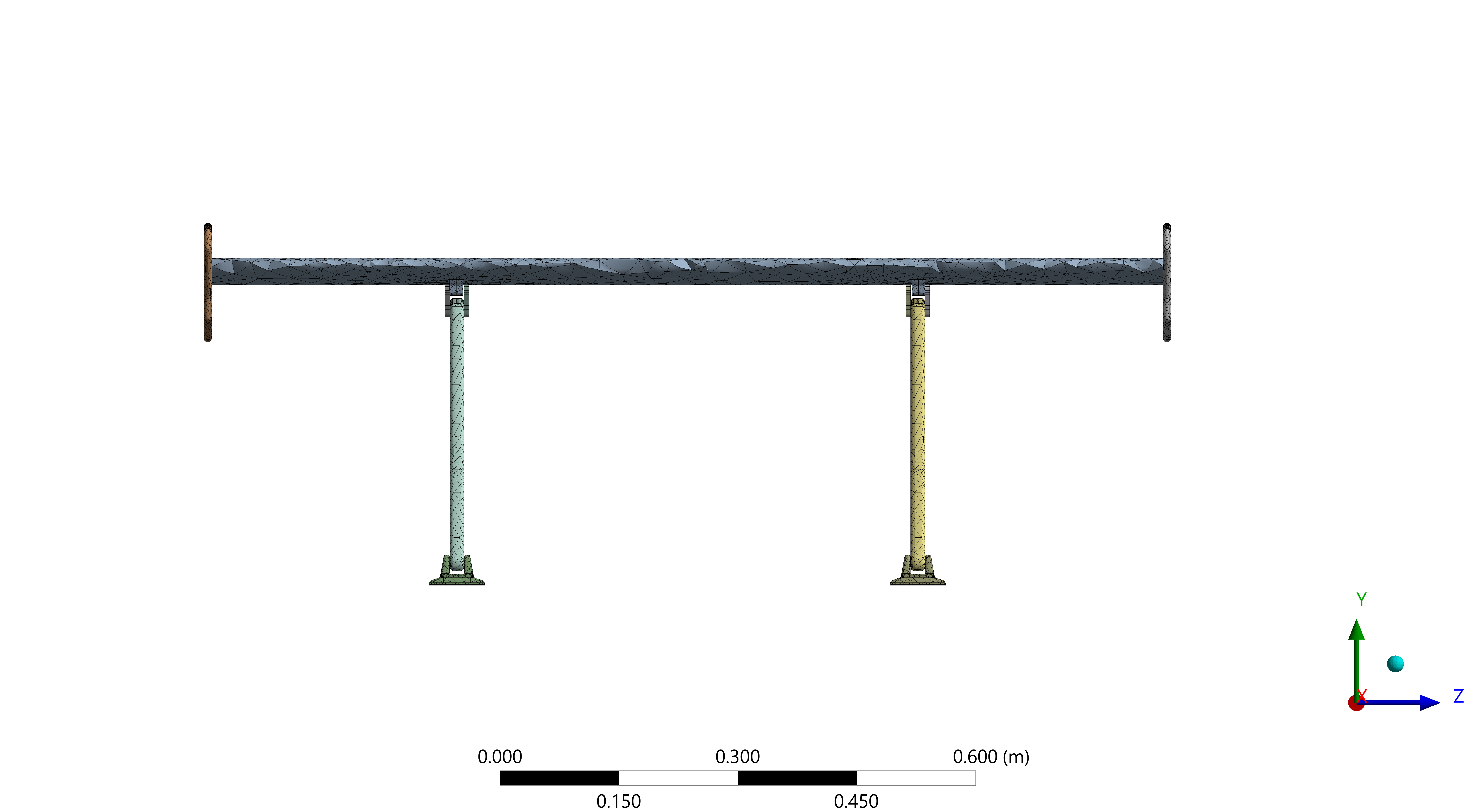
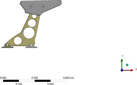
The analysis uses an open-source CAD assembly from the GrabCAD library. The spoiler consists of four main components: the main wing, endplates, brackets, and mounting bases. The main wing is a constant-chord, flat-plate element modeled as a solid body without in- ternal spars. Its bending stiffness is derived entirely from the full-depth section of the wing. The endplates are two thin plates bolted to the wing using a pair of generic fasteners. In the finite element model, these fasteners are idealized as bonded contacts applied across the bolt footprints to simplify the simulation. The brackets are dual sheet-metal structures featuring three concentric lightening holes for weight reduction. These brackets, or pedestals, are slightly raked forward to ensure aerodynamic clearance and are connected to the underside of the wing using clevis-style pins, which are represented in the model as frictionless cylindrical joints. Finally, the mounting bases are rectangular base plates located at the foot of each pedestal. These bases are rigidly secured to the vehicle deck and defined as fixed supports in the simulation. The spoiler geometry obtained from GrabCAD was validated against established automotive spoiler design parameters documented in literature to ensure aerodynamic realism and representativeness of production vehicle configurations. Dimensional analysis confirmed that the model’s key geometric parameters fall within the typical range of passenger vehicle spoilers. These specifications align with established airfoil profiles commonly employed in automotive spoiler design. Comparative analysis with documented real-world spoiler dimensions from academic CFD studies shows that the GrabCAD model exhibits geo- metric characteristics consistent with production automotive spoilers used in vehicles. While absolute aerodynamic optimization was not the primary objective of this material comparison study, the geometric validation ensures that the model represents realistic loading conditions and structural dimensions typical of automotive spoiler applications, thereby providing a meaningful basis for comparative material analysis without compromising the validity of the mechanical property comparisons5,6,7.
Material Models
Material choice has a profound impact on a spoiler’s static strength, stiffness, weight, and dynamic, or modal, behavior. This study compares three common materials – ABS (Acrylonitrile Butadiene Styrene) plastic, aluminum 6061-T6, and carbon-fiber-reinforced polymer (CFRP) to illustrate how their differing properties influence structural performance. The selection of ABS, aluminum 6061-T6, and quasi-isotropic carbon fiber reinforced polymer represents three distinct material categories that span the automotive spoiler market from mass production to high-performance applications, each offering unique advantages in cost, manufacturing, and performance characteristics. ABS plastic serves as the cost-effective baseline material, widely utilized in automotive exterior components due to its excellent moldability, impact resistance, and manufacturing economy, with studies demonstrating comparable mechanical properties to natural fiber alternatives in spoiler applications. Aluminum 6061-T6 represents the premium metallic option, offering superior machinability and strength-to-weight ratio characteristics essential for high-performance automotive applications. Academic research on 6061-T6 aluminum machining demonstrates its excellent surface finish capabilities and mechanical properties that make it suitable for precision automotive components. Quasi-isotropic CFRP represents the highest performance tier, offering exceptional strength-to-weight ratios but at significantly higher material costs, making it primarily suitable for luxury and motorsport applications. Current research indicates that while CFRP materials can achieve superior mechanical properties, their adoption remains limited by manufacturing costs and processing complexity, though advancing manufacturing techniques continue to improve their commercial viability for high-performance automotive exterior components8,9,10,11. Table 1 summarizes key properties of each material and elastic constants to be used. Below, we pro- vide context on each material’s characteristics, advantages, and drawbacks, and how these relate to spoiler performance. Accurate representation of material behavior is essential in finite-element simulations to predict stress distribution and deformation under aerodynamic loading. Therefore, materials were modeled according to their mechanical nature: ABS and aluminum as isotropic, and CFRP as quasi-isotropic due to its layered composite structure. This means that CFRP’s directional stiffness assumed uniform in-plane properties by orienting plies in multiple directions.
| Material | ρ (g/cm3) | E or E1/E2/E3 (GPa) | G (GPa) | ν | σT /σC (MPa) | τ (MPa) |
| ABS | 1.03 | 2.2 | 0.8 | 0.39 | 40 | 34 |
| Aluminum 6061-T6 | 2.70 | 69 | 26 | 0.33 | 310 | 207 |
| CFRP (quasi-iso) | 1.60 | 290 | 5 | 0.30 | 400 | 70 |
Table Column Definitions
The parameters listed in Table 1 define the mechanical behavior of each material used in the analysis. Below, each parameter is defined:
- ρ (density). Mass per unit volume presented in g cm-3; it directly influences the inertial terms and overall weight of the spoiler assembly.
- E or E1/E2/E3 (Young’s modulus). Resistance to uniaxial deformation. For isotropic ABS and aluminum, a single modulus E suffices; for orthotropic CFRP, three principal moduli (E1, E2, E3) capture directional stiffness.
- G (shear modulus). Material rigidity under shear loading; for composites, an in-plane equivalent value is specified.
- ν (Poisson’s ratio). Lateral contraction ratio in uniaxial tension, required for constitutive matrix completion.
- σT/σC (tensile/compressive strength). Ultimate strengths used to gauge failure indices.
- τ (shear strength). Maximum in-plane shear strength used for shear-governed safety checks. For isotropic materials (ABS, aluminum) this is the ultimate shear strength from datasheets; for CFRP it corresponds to the in-plane lamina shear allowable.
Strengths and safety–factor convention
For Aluminum 6061–T6, Table 1 lists the ultimate tensile strength, but all aluminum safety factors in Sec. 3.1 are computed against the yield strength to avoid permanent set. For ABS, the governing limit under bending is the ten- sile/flexural allowable; we use a conservative tensile value for SF calculations. For the quasi- isotropic CFRP, we report SF with respect to the in-plane fiber-direction tensile/compressive allowable.
Normalization convention
Because the spoiler geometry and volume are identical across materials, mass is proportional to density (m = ρV). To compare stiffness-to-mass performance, results are therefore normalized by density and reported as displacement per density (∆/ρ) and first-mode frequency per density (f1/ρ).
Aerodynamic Loading Scenarios
A calculated value of p ≈ 1 040 Pa is applied uniformly over the spoiler’s planform area to represent aerodynamic loading. Three scalar cases are considered, as shown in Table 2. These loading scenarios are intended to approximate the range of downforce levels a high- performance spoiler may encounter under realistic driving conditions, such as high-speed cornering or straight-line acceleration. This enables a comparative evaluation of structural performance under varying aerodynamic demands. These pressures therefore represent high- way to high-performance conditions. The uniform pressure assumption is a conservative simplification; the true surface loading is non-uniform and depends on geometry and flow state.
The aerodynamic pressure loads (520, 1 040, and 1 560 Pa) were derived using the dynamic pressure equation:
(1) 
where  is dynamic pressure, = 1.225 kg/m3 (standard air density), and V is vehicle speed. Simulations considered three representative speeds: 80 km/h (22.22 m/s), 120 km/h (33.33 m/s), and 160 km/h (44.44 m/s). Substituting:
p80 =  1.225 × (22.22)2≈ 302 Pa
p120 = 1.225 × (33.33)2≈ 680 Pa
p160 = 1.225 × (44.44)2≈ 1,207 Pa
These values were then scaled upward to account for spoiler planform effects, flow separation, and empirical amplification observed in published studies of rear spoilers resulting in the applied loads of 520, 1 040, and 1 560 Pa used in these simulations17,18,19.
| Case | Pressure (Pa) | Design Scenario |
| LC–1 | 520 | Service (50%) |
| LC–2 | 1,040 | Design (100%) |
| LC–3 | 1,560 | Ultimate (150%) |
Finite Element Procedure
The finite-element method (FEM) converted the spoiler’s elasticity problem into the discrete system
Ku = F
The solid was meshed into elements with nodal degrees of freedom; polynomial shape functions and the virtual-work statement produced element stiffness matrices, which were assembled into the global system. Solving yielded nodal displacements, and strains and stresses were then recovered from standard strain–displacement and constitutive relations
Mesh Description
The spoiler assembly was discretized using a 3D mesh composed of elements, well-suited for capturing curvature and geometric complexity. Mesh refinement was applied at stress-critical locations, including the bracket holes, clevis joints, and wing-to-bracket interfaces. The final mesh contained approximately 29,000 elements and 58,000 nodes. Figures of the spoiler mesh are provided below from three different angles.
To justify the working mesh of ∼29,000 elements, we performed an refinement check using three meshes (coarse ∼15k, medium ∼29k, fine ∼60k). Boundary conditions and loads were identical across meshes, with local refinement around fillets and mounting features. The governing response quantities were (i) maximum tip displacement and (ii) peak von Mises stress at the hotspot. Between the medium and fine meshes, the change in tip displacement was below a 2% tolerance and the change in peak stress was within a 5% tolerance, while the location of the stress hotspot remained unchanged. Accordingly, the ∼29k-element mesh was selected as the coarsest mesh that satisfies these convergence criteria, providing mesh- independent results. For modal analysis, the first natural frequency varied negligibly between the medium and fine meshes (within 2%), supporting the same mesh choice.
The finite element mesh was composed of tetrahedral elements to capture complex spoiler geometry. Tetrahedral elements are the industry standard for intricate solid bodies and pro- vide an effective balance of geometric fidelity and computational efficiency for the curved surfaces of the spoiler20.

Boundary Conditions
To replicate an in-service spoiler mounting scenario, the spoiler assembly is constrained by two fixed supports assigned to the underside of the pedestal base plates, treated as rigidly bolted to the vehicle deck. Real deck-lid/body panels have finite compliance; this study idealizes the mounts as rigid and does not include that flexibility. The aerodynamic pressure load is introduced as a spatially uniform pressure acting normal to the upper (suction-side) surface of the wing. Load magnitudes correspond to the service, design, and ultimate cases summarized in Table 2.
Modal Analysis
Modal analysis determines the natural frequencies and corresponding mode shapes of a structure in the absence of external damping. We compute undamped eigenfrequencies and mode shapes to compare materials on a consistent basis and to assess separation from a 30 Hz target. For light damping typical of metals, polymers, and CFRP laminates (order of a few percent of critical), the frequency shift is on the order of 10−3 relative (negligible for ranking and threshold checks). Damping chiefly governs response amplitudes near resonance rather than the eigenfrequencies themselves. Because we do not perform a forced-response analysis here, omitting damping avoids introducing uncertain estimates for joint, material, and interface losses without affecting the conclusions about mode placement or stiffness com- parisons21,22,23,24,25. Each natural frequency represents a resonant condition at which the structure can oscillate with minimal input energy. Knowledge of these frequencies is critical because if operational or environmental excitation coincides with a natural frequency, dynamic amplification and potentially catastrophic fatigue can occur. A modal analysis solver is used to compute the first six fundamental frequencies. Key outputs collected include natural frequencies and mode shapes with qualitative deformation patterns.
For a spoiler, the most concerning scenario is a low-frequency bending or torsional mode that coincides with road-induced vibration. Therefore, we aim to keep the first structural mode above 30 Hz for this vehicle’s spoiler.
Results and Discussion
Structural Analysis
The following tables show the effects of each of the prescribed loading cases on the spoiler for each material, solving for maximum tip displacement and peak stress. Across materials, load scaling is approximately linear in both displacement and stress, as expected for small-deflection elastic response, enabling direct comparison of safety-factor trends. To aid interpretation, concise observations are provided immediately after each table.
For ABS, the aerodynamic loading on the spoiler induces global bending, placing the lower surface in tension and the upper surface in compression. While shear stresses are present near the supports, the critical stresses arise in the tensile region of the cross-section. Since ABS generally exhibits lower tensile strength compared to compressive strength, the safety factor was evaluated with respect to the tensile/flexural limit, which represents the governing failure mode26,27.
For CFRP, the quasi-isotropic laminate exhibits anisotropic behavior, with comparatively high strength in fiber-aligned tension but reduced strength in compression and in-plane shear. Under bending, the laminate experiences significant compressive loading on the upper surface as well as interlaminar shear. Consequently, the compressive and shear limits were identified as the governing conditions for the safety factor, as these modes are more likely to control failure than the laminate tensile response28,29,30.
Load Case | Max Tip Displacement (mm) | Peak Stress (MPa) | Safety Factor |
| LC-1 (520 Pa) | 0.0537 | 14.088 | 22.00 |
| LC-2 (1 040 Pa) | 0.108 | 28.32 | 10.95 |
| LC-3 (1 560 Pa) | 0.162 | 42.48 | 7.30 |
Interpretation (Aluminum)
Displacements remain sub-millimetric across all loads, indicating high stiffness. Safety factors are computed using σy (yield) rather than σu, consistent with avoiding permanent set. Peak stresses scale proportionally with pressure yet remain well below the stated strength, yielding safety factors >7 even at LC-3. This suggests adequate static margin with minimal deformation for the aluminum spoiler in the examined regime.

| Load Case | Max Tip Displacement (mm) | Peak Stress (MPa) | Safety Factor |
| LC-1 (520 Pa) | 1.816 | 13.902 | 2.88 |
| LC-2 (1 040 Pa) | 3.63 | 27.803 | 1.44 |
| LC-3 (1 560 Pa) | 5.448 | 41.706 | 0.96 |
Interpretation (ABS)
Displacement is an order of magnitude larger than aluminum under identical loading, reflecting the lower stiffness. Safety factors for ABS are evaluated against the tensile/flexural limit. The safety factor trends downward with pressure and drops below unity at LC-3, indicating incipient failure under the highest aerodynamic load. Because bending places the lower face in tension, the tensile/flexural limit governs this assessment.
| Load Case | Max Tip Displacement (mm) | Peak Stress (MPa) | Safety Factor |
| LC-1 (520 Pa) | 0.165 | 27.51 | 14.54 |
| LC-2 (1 040 Pa) | 0.330 | 55.02 | 7.27 |
| LC-3 (1 560 Pa) | 0.495 | 82.53 | 4.85 |
Interpretation (CFRP)
Displacements are low despite the light weight, illustrating the favor- able stiffness-to-mass characteristics of the laminate. CFRP safety factors reported in Table 5 use the in-plane tensile/compressive allowable. Safety factors remain comfortably above unity across all load cases. Consistent with laminate behavior, compressive and in-plane shear al- lowables govern the margin under bending rather than tensile strength.
Modal Analysis
The following tables show the first six fundamental frequencies of the spoiler for each material.
| Mode | Frequency (Hz) |
| 1 | 7.258 |
| 2 | 22.625 |
| 3 | 25.257 |
| 4 | 30.945 |
| 5 | 34.984 |
| 6 | 70.457 |
| Mode | Frequency (Hz) |
| 1 | 25.738 |
| 2 | 80.297 |
| 3 | 89.722 |
| 4 | 109.660 |
| 5 | 124.000 |
| 6 | 250.500 |
| Mode | Frequency (Hz) |
| 1 | 21.575 |
| 2 | 58.423 |
| 3 | 69.286 |
| 4 | 86.162 |
| 5 | 91.132 |
| 6 | 201.690 |
Interpretation (Modal)
The ABS spoiler exhibits the lowest fundamental frequency, indicating greater susceptibility to low-frequency excitation and potential ride-induced resonance. Aluminum and CFRP show substantially higher natural frequencies, implying improved vibration robustness within typical automotive excitation bands.
Mass-normalized stiffness-to-mass results
We assess stiffness-to-mass using displacement per mass proxy ∆/ρ (smaller is better for static stiffness/mass) and first-mode frequency per mass proxy f1/ρ (larger is better for dynamic stiffness/mass). With identical geometry, these are proportional to ∆/m and f1/m. Values below use the representative design load LC–2 (1,040 Pa).
| Material | ρ (g/cm3) | ∆ (mm) | ∆/ρ (mm·cm3/g) | f1/ρ (Hz·cm3/g) |
| ABS | 1.03 | 3.63 | 3.524 | 7.047 |
| Al 6061–T6 | 2.70 | 0.108 | 0.0400 | 9.533 |
| CFRP (quasi-iso) | 1.60 | 0.330 | 0.206 | 13.484 |
Interpretation
Aluminum minimizes ∆/ρ (best static stiffness-per-mass); CFRP maximizes f1/ρ (best dynamic stiffness-per-mass); ABS trails on both.
Synthesis
Considering static and dynamic responses together: aluminum provides high margins with minimal deformation; ABS is deformation-limited and fails at the highest load; CFRP achieves low displacement and adequate safety factors with governing compression/shear limits. When normalized by mass, aluminum ranks best in static stiffness (∆/ρ) while CFRP ranks best in dynamic stiffness (f1/ρ); see Table 9. These observations align with the governing-limit rationale outlined above and support material selection toward aluminum or CFRP for the examined loading envelope.
Conclusion
This study quantified the structural response of a fixed-geometry rear spoiler across three materials—ABS, aluminum 6061-T6, and quasi-isotropic CFRP—subjected to three representative aerodynamic pressures (520, 1 040, 1 560 Pa). Finite-element simulations reveal clear trade-offs:
Findings
Aluminum delivered the smallest absolute deflections and the best static stiffness-to-mass (smallest ∆/ρ), while CFRP offered the best dynamic stiffness-to-mass (largest f1/ρ); ABS trailed on both mass-normalized metrics. ABS experienced large deflection (1.82–5.45 mm) and subcritical safety (SF ≤ 0.96 at 1 560 Pa), indicating probable failure; it is unsuitable for structurally loaded spoilers under high aerodynamic forces. A full failure mode assessment—incorporating the polymer’s nonlinear stress–strain response and a buck- ling eigenvalue study—would be required to predict post-yield behavior and local buckling of thin sections. Although beyond the current material-comparison scope, such analyses repre- sent important future work and do not affect the validity of comparing relative performance under identical loading. Modal analysis placed the first modes near 25.7 Hz (aluminum), 21.6 Hz (CFRP), and
7.26 Hz (ABS). Because the ABS first-mode frequency falls far short of the 30 Hz target, ABS is ruled out for this geometry unless major stiffening is introduced. These are below a typical 30 Hz target for components excited by road inputs, suggesting that modest structural stiffening and/or mounting refinements are warranted to mitigate resonance risk31.
Validation
The structural deflection results obtained in this study were validated against published finite element analyses of automotive spoilers and wings under aerodynamic loading. Andreassi et al. conducted CFD-FEM coupled analysis of racing car wings under high- speed conditions, reporting wing tip deflections that produced 4–5% differences from rigid configurations when using carbon fiber materials with elastic moduli comparable to this study. Similarly, Geisbauer et al. performed structural analysis of Formula One rear wings and documented stress levels on the order of 6.36 × 10⁶ Pa under aerodynamic loading, which aligned with the stress magnitudes observed in our ABS and aluminum models. Our calculated tip deflections of 1.8–5.4 mm for the aluminum spoiler under 520–1560 Pa loading compared favorably with NASA wing displacement studies, which demonstrated finite element prediction accuracies within 1.6% using similar computational methodologies.
While direct experimental validation data for automotive spoiler deflection under the specific loading conditions used in this study were limited in the open literature, the finite element methodology employed followed established protocols documented in aerospace and automotive structural analysis. The displacement-to-chord ratios and stress distribution patterns observed in our models fell within typical ranges reported for automotive exterior components under aerodynamic loading in motorsport applications. The primary contribution of this work lay in the systematic comparison of three distinct material systems under identical loading conditions rather than absolute deflection prediction, which maintained the validity of relative performance comparisons while acknowledging the limitations of absolute accuracy
without direct experimental validation32,33,34,35,36.
Limitations
The loading was represented by uniform pressure fields derived from dynamic pressure; real distributions are nonuniform and depend on vehicle geometry, angle of attack, and local flow separation. The CFRP was modeled as a quasi-isotropic laminate without ply-level failure criteria; progressive damage or matrix/fiber failure were not evaluated. Fastener compliance and joint preload were approximated, and thermal/environmental effects were neglected. These choices are appropriate for a comparative material study but may over- or under-estimate local stress concentrations. Modal damping was not modeled; while this can substantially reduce resonant amplitudes, it produces only negligible shifts in natural frequencies at light damping, so the reported mode ordering and mass-normalized rankings are unaffected. Mount/body-panel compliance was not modeled; the pedestal bases were treated as fixed (rigid) supports. This idealization likely underestimates static deflections and overestimates natural frequencies, so the reported values should be interpreted as optimistic bounds with respect to boundary flexibility. Because geometry and loading are identical across materials, the effect is expected to act largely as a common-mode shift, and the qualitative material ranking reported here is expected to remain unchanged.
Future work
(i) Couple fluid–structure interaction (FSI) to map realistic pressure fields and assess aeroelastic effects; (ii) incorporate laminate-level criteria for composites with progressive damage; (iii) include detailed joint models (bolt preload, contact/friction) and vali- date against bench tests; and (iv) add mesh-refinement to remove any uncertainty.
Overall, material selection exerts a first-order influence on spoiler structural performance: aluminum minimizes deflection for the studied geometry, CFRP provides superior performance per unit mass, and ABS should be avoided where significant aerodynamic loading is expected.
References
- Stanley R. Cole. Effects of spoiler surfaces on the aeroelastic behavior of a low-aspect-ratio rectangular wing. Technical Report NASA TM-102622, NASA Langley Research Center, 1990. [↩]
- Jr. Doggett, Robert V. Some effects of aerodynamic spoilers on wing flutter. Technical Report NASA TM-101230, NASA Langley Research Center, 1989. [↩]
- Ronald F. Gibson. Principles of Composite Material Mechanics. CRC Press, 4 edition, 2016. [↩]
- Composite materials handbook (cmh-17), volume 3: Polymer matrix composites – materials usage, design and analysis, 2002. MIL-HDBK-17/3F (superseded by SAE R-424); Accessed 2025-08-08. [↩]
- Ahmad Karaki, Mohammad Abu Sirreya, Majdi Zalloum, and Husein Amro. Enhancing vehicle performance through the application of airfoils as spoilers with movable trailing edge. F1000Research, 14:469, 2025. [↩]
- Rubel Chandra Das and Mahmud Riyad. Cfd analysis of passenger vehiclet various angle of rear end spoiler. Procedia engineering, 194:160–165, 2017. [↩]
- Sunny Patel, Shubham Jogani, Dip Chaklashiya, Dharmik Chodvadiya, Miten Naliyadhara, and Vaibhav Monpara. Design and analysis of a split spoiler to optimize downforce and turbulence. International Research Journal of Engineering and Technology, 11, 2024. [↩]
- Wanmin Yu and Li Jiang. Application of carbon fiber reinforced aluminum matrix composites in automotive industry. International Journal of Automotive Manufacturing and Materials, 3(2):3, Jun. 2024. [↩]
- Tomasz Trzepieciński and Sherwan Mohammed Najm. Current trends in metallic materials for body panels and structural members used in the automotive industry. Materials, 17(3), 2024. [↩]
- M.R.M. Rejab. Surface roughness optimization and machining research on 6061-t6 aluminum, 2024. Google Scholar Profile – Research on aluminum 6061-T6 machining and automotive applications. [↩]
- Agustinus Purna Irawan, I Wayan Sukania, et al. Manufacturing process of car spoiler product using continuous rattan fiber composite materials. International Journal of Mechanical Engineering and Technology (IJMET), 1(11):9–15, 2020. [↩]
- Dan J. Naus, Kenneth R. Corum, and Lynn B. Klett. Durability-based design criteria for a quasi-isotropic carbon-fiber-reinforced thermoplastic automotive composite. Technical Report ORNL/TM-2006/011, Oak Ridge National Laboratory, 2006. [↩]
- Farnell. Technical data sheet: Acrylonitrile butadiene styrene (abs). Online PDF, 2024. Shear strength 33.9 MPa. [↩]
- Thomasnet. All about 6061 aluminum (properties, strength and uses). Online Article, 2023. Shear strength 207 MPa. [↩]
- TenCate Advanced Composites. Tc275-1 quasi-isotropic fabric technical paper. Technical paper, 2023. [↩]
- MatWeb. Abs – acrylonitrile butadiene styrene datasheet. Online datasheet, 2024. Accessed September 24, 2025; Elastic modulus 2.2 GPa, shear modulus 0.8 GPa, Poisson’s ratio 0.39, tensile strength 40 MPa, density 1.03 g/cm³. [↩]
- John Anderson. EBOOK: Fundamentals of Aerodynamics (SI units). McGraw Hill, 2011. [↩]
- Mustafa Cakir. Cfd study on aerodynamic effects of a rear wing/spoiler on a passenger vehicle. Mechanical Engineering Master’s Theses, 2012. [↩]
- Chien-Hsiung Tsai, Lung-Ming Fu, Chang-Hsien Tai, Yen-Loung Huang, and Jik-Chang Leong. Computational aero-acoustic analysis of a passenger car with a rear spoiler. Applied Mathematical Modelling, 33(9):3661–3673, 2009. [↩]
- Teseo Schneider, Yixin Hu, Xifeng Gao, Jeremie Dumas, Denis Zorin, and Daniele Panozzo. A large-scale comparison of tetrahedral and hexahedral elements for solving elliptic pdes with the finite element method. ACM Transactions on Graphics (TOG), 41(3):1–14, 2022. [↩]
- Meherwan P. Boyce. Gas turbine engineering handbook. Elsevier, 2011. [↩]
- Dassault Systèmes. Viscous damping ratios for different systems and materials, 2016. Web Help Content Version: SOLIDWORKS 2016 SP05. [↩]
- Yukuan Dou, Jinguang Zhang, Xianglong Wen, Hui Cheng, and Haixin Liu. Free vibration characteristics of CFRP laminate with one-dimensional periodic structures. Polymers, 15(5), 2023. [↩]
- MIT Mathematics Department. Natural frequency and damping ratio. Course Materials 18-03 Supplementary Notes 13, Massachusetts Institute of Technology, 2004. [↩]
- Henrik Sönnerlind. How to model different types of damping in COMSOL multiphysics. COMSOL Blog, March 2019. [↩]
- Zorana Golubović, Ivan Danilov, Božica Bojović, Ljubiša Petrov, Aleksandar Sedmak, Žarko Mišković, and Nenad Mitrović. A comprehensive mechanical examination of ABS and ABS-like polymers additively manufactured by material extrusion and vat photopolymerization processes. Polymers, 15(21), 2023. [↩]
- Mehmet Akif Dundar, Gurpinder Singh Dhaliwal, Emmanuel Ayorinde, and Mohammad Al-Zubi. Tensile, compression, and flexural characteristics of acrylonitrile–butadiene–styrene at low strain rates: Experimental and numerical investigation. Polymers and Polymer Composites, 29(5):331–342, 2021. [↩]
- Ai jun Li, Jun jun Zhang, Fang zhou Zhang, Long Li, Shi peng Zhu, and Yun hua Yang. Effects of fiber and matrix properties on the compression strength of carbon fiber reinforced polymer composites. New Carbon Materials, 35(6):752–761, 2020. [↩]
- Srinivas Nunna, Anil R. Ravindran, Jens Mroszczok, Claudia Creighton, and Russell J. Varley. A review of the structural factors which control compression in carbon fibres and their composites. Composite Structures, 303:116293, 2023. [↩]
- Kirill Guseinov, Oleg Kudryavtsev, Alexander Bezmelnitsyn, and Sergei Sapozhnikov. Determination of interlaminar shear properties of fibre-reinforced composites under bi-axial loading: A new experimental approach. Polymers, 14(13), 2022. [↩]
- Ahmad Syihan Yusof Rashid et al. Improving the dynamic characteristics of body-in-white (biw) structure for noise vibration and harshness (nvh). The Scientific World Journal, 2014. [↩]
- Shun-Fat Lung and William L. Ko. Applications of displacement transfer functions to deformed shape predictions of the g-iii swept-wing structure. In Congress of the International Council of the Aeronautical Sciences (ICAS 2016), number DFRC-E-DAA-TN30944, 2016. [↩]
- Vennelakanti Sai Hemanth Kumar. Deflection of formula one race car rear wing using numerical simulations. International Journal of Engineering and Advanced Technology (IJEAT), 2022. [↩]
- Luca Andreassi, Vincenzo Mulone, Pier Paolo Valentini, and Leonardo Vita. A cfd-fem approach to study wing aerodynamics under deformation. Technical report, SAE Technical Paper, 2004. [↩]
- Sunil Patil, Robert Lietz, Sudesh Woodiga, Hojun Ahn, Levon Larson, Ronald Gin, Michael Elmore, and Alexander Simpson. Fluid structure interaction simulations applied to automotive aerodynamics. Technical report, SAE Technical Paper, 2015. [↩]
- Daniel Wood, Martin A. Passmore, and Anna-Kristina Perry. Experimental data for the validation of numerical methods-sae reference notchback model. SAE International Journal of Passenger Cars-Mechanical Systems, 7(2014-01-0590):145–154, 2014. [↩]


