
Abstract
Most previous studies have addressed centralized platooning, which is suitable for highway systems, has limited scalability and low fault tolerance, making it unsuitable for urban areas and high-dynamic scenarios. Decentralized platooning, where every vehicle has the capability to communicate with nearby vehicles, is the most suitable approach in urban environments. The objective of this work was to propose a low-cost, reliable localization and communication system appropriate for a decentralized vehicle platooning system. This work proposes a decentralized vehicle platooning system utilizing low-cost components – the Jetson Nano and Pixhawk for localization, and the nRF24L01+ for inter-vehicle communication. Comprehensive testing was conducted in indoor environments to analyze latency, reliability, and accuracy across various distances, baud rates, and packet sizes. Results showed 100% reliability and a latency of 3 ms for distances of up to 20 meters with 32-byte packets. The localization system, based on Pixhawk and Jetson Nano, achieved 99% accuracy in open environments and 98% in dense environments. A comparative study indicates that the suggested system achieves a balance between performance and cost, providing meter-level localization and highly reliable communication. Future improvements involve the integration of RTK-GPS for centimeter-level precision, cybersecurity features, and string stability control. The nRF24L01+-based communication system necessitates a comprehensive outdoor evaluation under real-world conditions to validate its reliability and suitability for vehicle platooning. However, preliminary results indicate that a decentralized architecture based on open-source, low-cost platforms has the potential to meet the practical requirements of small-scale urban platooning and open the way for scalable deployment.
Keywords: Affordable, Decentralized Platooning, Jetson Nano, Localization, nRF24L01+, Pixhawk, Platooning, Wireless Communication.
Introduction
Increasing transportation demand is leading to higher energy demand, enhanced CO2 emissions (causing global warming), increased road congestion, and more road accidents.
The problem can be solved mainly by implementing a vehicle platooning system, which is affordable (to increase adaptability) and also suitable for both highway systems and urban setups effectively.
Increase In Adaptability With Affordable Autonomous Vehicles
A study by researchers from the University of Michigan and Delft University of Technology developed a model forecasting Autonomous Vehicle (AV) adoption. It was found that with an annual AV price reduction of 5% from an initial price of $40,000, and high user satisfaction, AVs could achieve around 85% market share in 30 years1.
Advantages of Decentralized Platooning
A decentralized system reduces communication delays and increases reliability, as each vehicle communicates with others and does not rely on a central controller. Since each vehicle handles its own communication and decision-making process, decentralized platooning is more scalable. It also has higher fault tolerance, which means that if one vehicle encounters an issue, the rest of the platoon can continue to operate effectively2.
Recent platooning research focuses on the need for decentralized solutions to address scalability and robustness in dynamic real-world conditions. One study presented a two-level decentralized learning framework in which each vehicle decides, based on its local knowledge, whether to form or join a platoon3. In another study, a deep reinforcement learning framework was developed that enabled platoons to coordinate at signalized intersections in mixed traffic conditions, thereby improving traffic throughput through decentralized control4. A further study demonstrated a “join-in-the-middle” behavior for dynamic platoons, whereby vehicles can join a mobilizing platoon through local decision-making protocols and decentralized control5.
Establishing Affordable & Reliable Technologies for The Vehicle Platooning System
Scope
Vehicle platooning requires a robust and reliable inter-vehicle communication system, as well as an effective localization system. As part of this project, an nRF24L01+ wireless module was used to establish wireless communication between two Arduino Due boards. A CAN (Controller Area Network)-based wired communication system was also established between the Arduino Due and
Jetson Nano to determine the viability of this system for intra-vehicle communication. The localization system was established by using Pixhawk (integrated with GPS) and Jetson Nano. Additionally, research was conducted to determine that Pixhawk and Jetson Nano are the most inexpensive technologies for localization, and a low-cost nRF24L01+ wireless module can be explored for urban vehicle platooning.
While previous work provides a solid foundation in coordination algorithms and high-accuracy localization, minimal effort has been focused on integrating low-cost, modular, and open-source technology aimed at decentralized vehicle platooning, particularly for urban and community-scale deployments. Existing literature tends to presume high-end GPS, cellular infrastructure, or commercial-level AI hardware, thereby creating a disincentive for low-cost implementation. This study bridges that gap by introducing a proof-of-concept that combines the nRF24L01+ for wireless communication and the Pixhawk–Jetson Nano for localization. This study demonstrates the feasibility of utilizing low-cost systems to achieve high-accuracy localization and reliable inter-vehicle communication, paving the way for further studies on scalable autonomous vehicle solutions.
Background research
Intra-vehicle communication
A reliable and robust intra-vehicle communication system is necessary for real-world vehicle platooning. Wired CAN-based in-vehicle communication has been utilized for decades. Key features of CAN-based Communication, which are ideal for Vehicle Platooning: –
- Real-time Communication:Platooning requires real-time coordination. CAN’s high-priority message arbitration capability can provide this6.
- Multi-Master Architecture: CAN supports multiple electronic control units (ECUs) that communicate data on a shared bus, eliminating the need for a host computer. This increases the reliability and flexibility of the system and also helps reduce costs (by minimizing wiring) and simplify system design6,7.
- Messages and Data Identifiers:The ability for users to define message identifiers enables system designers to provide specific identifiers for different data types, such as speed control, location tracking, or sensor data. Such flexibility promotes orderly and effective processing of the data throughout the network.
- Safety: CAN has robust error detection and handling, in addition to acknowledgement and retransmission. This renders CAN-based communication extremely reliable, a requirement for safety.
- Synchronization: CAN’s synchronization features are integral to modern automotive systems, enabling accurate coordination among ECUs for safety-critical applications like braking and acceleration. In systems like vehicle platooning, this synchronization allows several vehicles to operate safely and effectively as a single unit.
CAN-Based Communication Using Arduino Due and Jetson Nano
Arduino Due is ideal for low-level hardware communication and real-time control (e.g., CAN-based communication), whereas Jetson Nano is AI-enabled and more suitable for processing power, machine learning, and higher-level decision-making (e.g., sensor fusion and vehicle coordination).
Arduino Due: The Arduino Due can utilize CAN (Controller Area Network) communication to receive and transmit data messages, including vehicle status, sensor data, and vehicle control commands such as speed control and relative position. It provides a real-time communication interface among vehicles.
Jetson Nano: Is known for intensive tasks like vehicle localization, data fusion from different sensors, and high-level decision-making. These capabilities will enable the Jetson Nano to handle the overall coordination of the platoon. It is also capable of image processing, deep learning, or object detection tasks when integrated with cameras8.
Inter-Vehicle Wireless Communication
Inter-vehicle communication is key for platooning and demands a wireless technology that is reliable, fast, and scalable. The nRF24L01+ transceiver module can be explored for its capabilities in vehicle platooning applications. Here is a detailed overview of the key features of nRF24L01+, which make it suitable for inter-vehicle wireless communication.
- Bi-directional communication:The nRF24L01+ supports two-way data communication through its Enhanced ShockBurst™ protocol. The protocol includes automatic packet retransmission and acknowledgment, enabling guaranteed communication between devices, a significant requirement for providing synchronization in vehicle platooning applications9.
- Multiple communication channels:Operating in the 2.4 GHz ISM band, the nRF24L01+ has 125 channels to choose from. This allows separate communication links to be established between different vehicle pairs, reducing interference9.
- Enhanced ShockBurst™: Enhanced ShockBurst™ is a sophisticated, packet-based data link layer designed to incorporate key features such as automatic packet assembly and timing, automatic packet acknowledgment, and packet retransmission capability. This sophisticated technology, known as Enhanced ShockBurst™, is specifically designed to provide support for ultra-low-power and high-performance communication, while remaining compatible with low-cost host microcontroller implementations. Furthermore, the various features provided by Enhanced ShockBurst enable extreme power efficiency gains in both bidirectional and unidirectional systems. All this is without adding host controller complexity, thereby simplifying integration efforts9
Enhanced ShockBurst™ builds and schedules data packets for transmission. When received, it searches for a valid address in the incoming signal. Once identified, it demodulates the packet and verifies it using CRC (Cyclic Redundancy Check). If the packet is valid, the payload is moved into an empty slot in the receiver’s (RX) FIFO (First-In-First-Out). ShockBurst™ manages all high-speed bit handling and timing9.
Enhanced ShockBurst™ offers packet transaction management on a reliable two-way data link by automating the process. It is a packet exchange between a Primary Receiver (PRX) and a Primary Transmitter (PTX) that starts with the transmission of the packet by the PTX. The exchange is completed when the PTX gets an ACK packet from the PRX. The PRX can include user data in the ACK packet to provide a two-way data connection9.
Enhanced Shockburst™ packet format:The Enhanced ShockBurst™ packet contains a preamble, address, packet control, payload, and CRC field (Figure 1)9.

Figure 1 : Enhanced Shockburst™ packet format10
Preamble – The preamble synchronizes the receiver demodulator to the bit stream. It is a single byte, either 01010101 or 10101010. If the address starts with 1, it initializes to 10101010; if it begins with 0, to 01010101. This gives enough transitions to stabilize the receiver.
Address – This is the recipient’s address. An address makes sure that the packet is detected and received by the correct receiver, preventing accidental cross-talk between multiple nRF24L01+ systems.
Packet control field – The control field holds a 6-bit payload length, a 2-bit PID, and a 1-bit NO_ACK flag.
The payload field indicates the length of the payload in bytes, from 0 through 32 bytes.
The PID 2-bit field is utilized to define whether the packet is new or a retransmission.
The Selective Auto Acknowledgement option processes the NO_ACK flag. The flag is used only when the auto-acknowledgement mode is enabled. The flag is set high to notify the receiver not to auto-acknowledge the packet.
Payload – Payload is user-defined packet data, 0 to 32 bytes, that is transmitted over the air when sent to an nRF24L01+.
CRC – It is a mandatory error detection technique in packets, calculated over the address, Packet Control Field, and Payload, with 1 or 2 bytes.
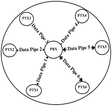
- Addressing and network topology: Each nRF24L01+ can communicate with up to six other modules, each with a dedicated address. This enables the achievement of complex network topologies, such as leader-follower topologies in platooning. The PRX uses MultiCeiver™ (Figure 2) and Enhanced ShockBurst™ to accept packets from multiple PTXs. It routes the ACK packet to the appropriate PTX by using the received data pipe address as a TX address9.
Preamble – The preamble synchronizes the receiver demodulator to the bit stream. It is a single byte, either 01010101 or 10101010. If the address starts with 1, it initializes to 10101010; if it begins with 0, to 01010101. This gives enough transitions to stabilize the receiver.
Address – This is the recipient’s address. An address makes sure that the packet is detected and received by the correct receiver, preventing accidental cross-talk between multiple nRF24L01+ systems.
Packet control field – The control field holds a 6-bit payload length, a 2-bit PID, and a 1-bit NO_ACK flag.
The payload field indicates the length of the payload in bytes, from 0 through 32 bytes.
The PID 2-bit field is utilized to define whether the packet is new or a retransmission.
The Selective Auto Acknowledgement option processes the NO_ACK flag. The flag is used only when the auto-acknowledgement mode is enabled. The flag is set high to notify the receiver not to auto-acknowledge the packet.
Payload – Payload is user-defined packet data, 0 to 32 bytes, that is transmitted over the air when sent to an nRF24L01+.
CRC – It is a mandatory error detection technique in packets, calculated over the address, Packet Control Field, and Payload, with 1 or 2 bytes.
- Addressing and network topology: Each nRF24L01+ can communicate with up to six other modules, each with a dedicated address. This enables the achievement of complex network topologies, such as leader-follower topologies in platooning. The PRX uses MultiCeiver™ (Figure 2) and Enhanced ShockBurst™ to accept packets from multiple PTXs. It routes the ACK packet to the appropriate PTX by using the received data pipe address as a TX address9.

- Data rate and range considerations:The module supports data rates of 250 kbps, 1 Mbps, and 2 Mbps. Lower data rates can be used to increase the range and reliability of communications, allowing vehicle links to be established at various distances9.
- Error handling and retransmission:Acknowledgment packets and automatic retransmission enhance the reliability of communications by guaranteeing that control messages are received correctly. The Enhanced ShockBurst™ protocol supports these features, including automatic packet assembly and timing9.
Comparison Of nRF24l01+ with Other Wireless Technologies
A cost-benefit analysis was conducted for the nRF24L01+ wireless communication module in contrast to other wireless technologies on the market.
nRF24L01+
Range – In open air with clear line-of-sight, an nRF24L01+ can cover on the order of tens to hundreds of meters with simple antennas, and approach ~1 km with amplified modules and good antennas. In contrast, any significant obstacles or ground-level placement will shrink that range substantially11,12.
Data Rate – The nRF24L01+ supports air data rates of 250 kbps, 1 Mbps, and 2 Mbps; however, the effective throughput for user data is significantly lower in practice. While the nRF24L01+ can be configured to operate at up to 2 Mbps, real-world applications often achieve an effective throughput of ~0.01–0.05 Mbps per stream, depending on payload sizes and acknowledgment, which is about 50% higher than ZigBee11,13.
Latency – Measured latencies for nRF24L01+ links are relatively low (tens of milliseconds) and significantly better than those of protocols like ZigBee. In vehicle communication trials, nRF24L01+ links exhibited one-hop message latency ranging from ~40 ms (best) to ~300–350 ms (worst case). In practice, a well-configured nRF24 network (with auto-acknowledgment and minimal processing delays) can achieve a latency of tens of milliseconds for small packets under good conditions, rising to a few hundred milliseconds under poor link conditions or heavy retry scenarios14.
Power Consumption – One advantage of the nRF24L01+ is its low power operation. Empirical measurements show the transceiver drawing roughly 13–16 mA when actively transmitting or receiving in typical configurations15.
Interference Resilience – Raw nRF24 links are susceptible to 2.4 GHz noise. Still, with careful channel selection and possibly frequency-hopping, they have shown robust performance (≪1% loss) even in the presence of Wi-Fi, outshining many integrated Wi-Fi or ZigBee solutions in reliability under interference16.
Scalability – The nRF24L01+ is often used in star or mesh networks, and experiments have explored its scalability with many nodes. The device supports up to 6 logical addresses in hardware for listening (e.g., for star networks), but more complex topologies are enabled by software protocols (e.g., RF24Network, custom TDMA, etc.). In one of the research studies, up to 3-hop chains were tested, and it was noted that while the throughput per hop dropped only slightly, maintaining routing in larger topologies can be challenging without disconnections15.
Reliability and Suitability for safety-critical use – Multiple studies with real-world tests report very high reliability (≳99% successful packet delivery) for nRF24L01+ links in mobile and robotic scenarios, provided that features like acknowledgements/retries and proper antenna/channel configurations are used. This level of performance suggests the nRF24L01+ can be suitable for certain safety-critical wireless links (such as a fail-safe vehicle communicator or robot telemetry), as long as network design best practices are followed14,17.
Cost – ≈ $5 per node (plus a minimal microcontroller unit). No dedicated gateways needed.
LoRa (Long Range)
Range – LoRa’s communication range is one of its strongest features. LoRa links can span a few km in urban areas and tens of km in rural or line-of-sight conditions18.
Data Rate – LoRa’s long-range capabilities come at the cost of reduced data throughput. It has modest data rates, typically ranging from approximately 0.3 kbps to around 50 kbps19.
Latency – LoRa can achieve latency on the order of a few hundred milliseconds for a single short packet, but network-level latency (from sensor to application) can rise to seconds if duty-cycle backoffs or multiple hops are involved. This is acceptable for delay-tolerant IoT applications but challenging for time-critical use cases without protocol enhancements18.
Power Consumption – A well-configured LoRa device can often operate for several years on a battery for low reporting rates. For example, LoRa radios, such as the Semtech SX127x series, typically draw on the order of tens of milliamps when transmitting at full power and only microamps to a few milliamps in sleep or listen mode18.
Interference Resilience – LoRa is considered highly robust in noisy environments relative to other LPWANs. According to one study, its modulation is “resistant to fading and interference by design,” but achieving near-100% reliability may require careful network planning or enhancements when interference and traffic increase20.
Scalability – There are real deployments with hundreds or thousands of nodes. As device density increases, network capacity and reliability degrade due to the increasing probability of collisions and duty-cycle limitations. Researchers have identified scalability and throughput as key challenges associated with an increasing number of devices21.
Reliability and suitability for safety-critical use – LoRa is gaining a foothold in safety-critical systems; however, achieving the necessary ultra-high reliability and low latency pushes the standard LoRaWAN to its limits, often necessitating augmented solutions, as evidenced by recent Research22,23.
Cost – LoRa modules are offered at a low price, thus making them suitable for a range of applications. For example, the RFM95W LoRa module is priced between $1.90 and $4.90 per module, subject to the supplier and the quantity ordered.
ZigBee
Range – ZigBee (IEEE 802.15.4) links are short-range, typically spanning a few meters to a few dozen meters in practice. A standard 2.4 GHz ZigBee radio is rated for roughly 30 m indoors and over 200 m line-of-sight outdoors under ideal conditions24.
Data rate – The data throughput of the Zigbee protocol can reach up to 250 Kbps, depending on the number and types of nodes, transmission medium, operating frequency, and allocated bandwidth. However, it varies greatly and is reduced to 4.5–5 Kbps in a real-world scenario for point-to-point communication with actual transceivers25.
Latency – One-hop ZigBee links introduce only tens of milliseconds of latency, which is relatively low for many IoT applications, but adding hops or encryption will increase the delay26.
Power Consumption – A significant strength of ZigBee/802.15.4 is its low power requirements, making it popular for battery-operated devices. The transmit and receive currents are on the order of only a few tens of milliamps for typical modules27.
Interference Resilience – ZigBee is comparatively robust against 2.4 GHz interference. In one study, ZigBee’s one-hop message delay remained near 60 ms across distances of up to 50 m, even with heavy Wi-Fi traffic on the 2.4 GHz band27.
Scalability – ZigBee is designed for mesh networking and supports large networks in principle. However, practical scalability is limited by the shared medium and duty cycle. Recent studies have concluded that ZigBee networks are well-suited for dozens of nodes with low data rates; however, high node densities or heavy traffic can lead to congestion24,27.
Reliability and suitability for safety-critical use – ZigBee’s limitations, like low throughput, CSMA delays, and limited range, mean it is not ideal for real-time safety-critical control loops that require guaranteed low latency and zero packet loss. The vehicle platooning/formation study explicitly recommended ZigBee only for non-critical inter-vehicle messaging and should be limited to small, non-time-critical packets such as status updates28.
Cost – ≈ $44 + coordinator (~ $20) per node. Low-power PAN; no license fees.
ESP-NOW
Range – ESP-NOW generally achieves a range comparable to or greater than that of standard Wi-Fi and Bluetooth Low Energy (BLE) in similar conditions. In direct-line-of-sight tests, maximum ranges of approximately 180–200 m have been demonstrated with on-board antennas. One comparative study found that ESP-NOW’s range (~185 m) was more than double that of Wi-Fi (~84 m) and over 12 times that of BLE (~15 m) using identical ESP32 hardware29.
Data rate – ESP‑NOW trades off throughput for simplicity and range. It uses a base data rate of 1 Mbps at the PHY layer by default, but the effective application-level throughput is lower30. One study reported ESP-NOW throughput ≈of ~0.59 Mb/s (588 kbps) under optimal conditions, compared to ~2.0 Mb/s for Wi-Fi and 0.94 Mb/s for BLE in the same setup31,32.
Latency – A key advantage of ESP‑NOW is its low communication latency. Because it is connectionless and lightweight, one-way transmission times are very short. Measurements indicate that an ESP-NOW packet can be delivered in approximately 1–2 milliseconds under optimal conditions29.
Power Consumption – Several studies highlight ESP‑NOW’s low power operation relative to Wi-Fi. The savings come from the duty cycle: ESP-NOW can wake, send a short packet, and return to sleep more quickly. One ESP-NOW optimization study introduced “Sync-ESP-NOW” with synchronized beacons, achieving ~90% energy reduction compared to a device that kept its radio constantly on, listening for messages33.
Interference resilience – while ESP‑NOW shares spectrum with Wi-Fi, it has proven robust for moderate levels of interference; critical applications can further mitigate issues by using dedicated Wi-Fi channels for ESP‑NOW communication to avoid overlap with nearby Wi-Fi networks32.
Scalability – ESP-NOW is designed for small to medium-sized peer-to-peer networks. It supports star and mesh-like topologies, but there are limits on the number of peers due to memory and address table constraints. An ESP32 in station mode can have up to 10 encrypted peer connections, and in total (encrypted and unencrypted), an ESP-NOW network should not exceed 20 devices per transceiver30.
Reliability and suitability for safety-critical use – Research indicates that ESP-NOW offers very high reliability at short ranges and deterministic low latency, but, like any wireless technology, it can suffer reduced reliability at the edge of its range. In strong signal conditions (within a few tens of meters indoors or ~50 m line-of-sight outdoors), ESP‑NOW achieves >99% packet delivery with one or two retransmissions, effectively providing a near-zero packet loss link. However, caution is warranted for mission-critical use. Several studies emphasize that range and reliability can degrade suddenly in unfavorable conditions – for instance, packet loss shot up from 0% to ~17% when an ESP‑NOW node moved just beyond ~55 m in one experiment, and beyond ~60–70 m no packets got through29 Cost – Low.
Dedicated Short-Range Communications (DSRC – IEEE 802.11p)
Range – IEEE 802.11p (DSRC) was designed for a “several hundred meters” range. In practice, a line-of-sight (LOS) reliable range is on the order of a few hundred meters34.
Data Rate – DSRC uses 10 MHz channels with raw PHY rates 6, 9, 12, 18, 24, 27 Mbps35.
Latency – DSRC is optimized for low latency. In simulations, DSRC V2I delays were ≪100 ms (typically a few ms) even under load36.
Power Consumption – Typical DSRC OBUs (On-Board Unit)/RSUs (Road Side Unit) transmit at up to 23 dBm EIRP (≈200 mW)31.
Interference Resilience – DSRC uses CSMA/CA (listen-before-talk). Under light load, it works well, but in dense scenarios, collisions rise. According to a study, an increasing number of channel collisions have occurred, and larger latency problems are expected to arise as the penetration rate of WAVE/DSRC devices rises. DSRC handles moderate traffic reliably; under heavy congestion, collisions spike36,37.
Scalability – Studies show that DSRC packet delivery remains very high, even with thousands of vehicles per hour. For example, in V2I simulations, DSRC maintained a PDR of over 96% at up to 1,500 vehicles per hour30. However, as density increases, channel occupancy also rises. Without congestion control, DSRC collision rates increase, resulting in higher latency and packet loss beyond ~1000 vehicles per hour37.Reliability and suitability for safety-critical use – DSRC was designed for vehicle safety. It supports 10 Hz beaconing (100 ms) as required by standards31. The standard’s multi-channel and CCH/SCH design isolates safety messages. In practice, DSRC has been used in emergency braking and platooning trials (500 m engagement range), and is generally considered capable of the required reliability for collision avoidance and platooning in normal traffic34.
Cost – Moderate; requires investment in special infrastructure.
Cellular Vehicle-to-Everything (C-V2X)
Range – Recent open-access studies consistently report that C-V2X (LTE/5G V2X) offers a significantly extended range compared to DSRC. According to one study, C-V2X coverage extends up to ~10 km in ideal conditions38.
Data Rate – C-V2X also supports substantially higher data rates. One of the simulation studies cites a raw data rate of up to ~100 Mbps38.
Latency – C-V2X is designed for lower latency than DSRC. Typical figures are ≈20 ms end-to-end for C-V2X (PC5 sidelink) versus ≈50 ms for DSRC38.
Power Consumption – Open literature has few direct measurements of C-V2X power consumption; however, system parameters suggest higher power consumption compared to DSRC. For example, one simulation setup used 40 dBm transmit power for C-V2X (LTE) vs 20 dBm for DSRC36.
Interference Resilience – C-V2X (especially Mode 4/5 scheduling) is generally more robust to interference than DSRC’s contention-based access. One analysis observes that C-V2X “improves resilience to interference” relative to IEEE 802.11p39.
Scalability – Cellular V2X scales more gracefully to high vehicle counts. Studies report that C-V2X maintains robust communication over several km even in high-density urban traffic, whereas DSRC’s contention leads to congestion38.
Reliability and suitability for safety-critical use – C-V2X’s 20 ms latency meets the <50 ms safety target for emergency braking/avoidance requirement32. Platooning requires ~10–25 ms end-to-end and >90% packet delivery ratio; C-V2X technology is explicitly designed to support these stringent needs40.
Cost – On-Board unit cost is similar to DSRC. It utilizes current cellular networks but will require subscription fees and infrastructure upgrades.
UWB (Ultra-Wideband)
Range – Typically up to ~30 m in practice41; specialized configs can reach ~290–300 m42.
Rate – Raw PHY rates up to ~6–7 Mbps on COTS UWB modules42; 802.15.4a/z allows ≈100+ Mbps in theory (impulse-UWB).
Latency – Very low (order 1–2 ms single-hop)41.
Power Consumption – Ultra-low energy per pulse. UWB transceivers use only μW–mW in idle/sleep and tens of mA in TX/RX; overall energy use is low43.
Interference Resilience – Wideband pulses are immune to narrowband noise41; experiments show negligible range impact under light RF interference44.
Scalability – High potential density. Theoretically supports thousands of tags per cell45.
Reliability and suitability for safety-critical use – Centimeter-level ranging, less than 2 ms latency, and high update rates suit real-time localization (collision avoidance, platooning). Reliability in dynamic environments is high41.
Cost – Relatively high; requires dedicated UWB anchors/tags and infrastructure41.
BLE (Bluetooth Low Energy)
Range – Individual links can span up to a few hundred meters line-of-sight. One of the field tests of BLE 5 found communication ranges up to ≈300 m under favorable conditions46.
Rate – In practice, BLE Mesh throughput is very low, on the order of tens of kilobits per second. One analysis measured only ~60 kbps effective throughput, even when using BLE 5’s 2 Mbps physical rate, due to advertising and protocol overhead47.
Latency – In a controlled 10-node experiment (nodes ≈1‑and 2 m apart), median hop-to-hop latency was ≈4.5 ms, but this grows rapidly in larger networks48.
Power Consumption – Measured idle current for a BLE Mesh relay is on the order of a few milliamps. In one testbed, each relay drew ≈6.2 mA at 3.3 V when constantly scanning. BLE chipsets are designed to be inexpensive and energy-efficient; however, BLE Mesh generally consumes more power than single-hop BLE or other low-power mesh networks due to the flooding protocol48.
Interference Resilience – BLE Mesh is quite vulnerable to 2.4 GHz interference. By specification, only three advertising channels (out of 40 BLE channels) carry all the mesh traffic. If those channels are congested (e.g., by Wi‑Fi or Bluetooth Classic), BLE Mesh packets collide and are lost. In practice, experiments show BLE Mesh suffers significant packet loss under heavy Wi‑Fi use49.
Scalability – BLE Mesh is theoretically scalable to large numbers (the spec allows up to ≈32 000 node addresses). However, flooding inherently limits practical scalability. Each new relay rebroadcasts every message, leading to a “broadcast storm” where the medium becomes saturated in dense networks. Studies find that reliability and latency degrade sharply as node count increases49.
Reliability and suitability for safety-critical use – BLE Mesh was designed for IoT (e.g., lighting, sensors), not for real-time vehicular control. It provides no deterministic delivery guarantees, and its flooding and jitter mean that end-to-end latency and reliability are not bounded. Vehicular safety use cases (e.g., platooning) often demand sub-100 ms updates with greater than 99.9% reliability. BLE Mesh’s measured latencies (hundreds of ms) and packet loss under interference suggest it cannot meet these requirements45.
Cost – A key advantage of BLE Mesh is low cost and ubiquity. BLE radio chips are mass-produced (used in smartphones, etc.), so node cost is low50.
nRF24L01+ was selected due to its optimal balance of low latency, high reliability, and cost-effectiveness. In contrast to ZigBee and BLE Mesh, which exhibit high delays and scalability limitations in mobile or dense scenarios, the nRF24L01+ has a latency of 40–300 ms. It has shown over 99% packet delivery in mobile robotic field tests. Although LoRa offers a more extended range, its low throughput and high latency are not suitable for platooning applications. DSRC and C-V2X also provide good performance but at the expense of high deployment costs, hardware complexity, and infrastructure dependence. In contrast, nRF24L01+ modules are low-power, can be used in the 2.4 GHz band, allow multi-hop communication using custom protocols, and cost around $5 per node, making them well-suited to low-cost, decentralized platooning systems with stringent latency and reliability requirements.
nRF24L01+ can be leveraged in decentralized platooning by using one of the following communication patterns.
- Predecessor-Follower: Each vehicle communicates with its immediate predecessor. Maximum of one direct peer per vehicle.
- Predecessor-Leader-Follower: Each vehicle communicates with its immediate predecessor and platoon leader. A maximum of two direct peers per vehicle will occur.
- Two-Hop or Bidirectional: Each vehicle communicates with its predecessor and follower. A maximum of two direct peers per vehicle will occur.
- Neighbor-based/Consensus-based: Each vehicle communicates with 2 to 4 vehicles.
Localization System for Vehicle Platooning
| Solution | Localization Accuracy | Update Rate | Estimated cost per vehicle |
| RTK-GPS | ~0.02 m (centimeter-level)51 | Up to 20 Hz | $200 – $300 (ZED-F9P – GPS module supporting RTK + antenna; excludes host system) |
| DWM1001 | ~0.1 m (10 cm) | ~10 Hz | $100 – $150 per tag + anchors (~ $300+ total) |
| Sensor Fusion (GPS + IMU EKF) | ~2–3 m (GPS nominal) | 10–50 Hz (GPS at 5–10 Hz, IMU up to 100 Hz) | $30 – $60 (standard GPS + IMU module) |
| Pixhawk + Jetson Nano (Standard GPS) | ~1–2 m | 10–50 Hz (from MAVLink EKF2/3 outputs) | $120 – $180 (Pixhawk ~ $100, Jetson ~ $60, GPS ~ $20) |
| Pixhawk + Jetson Nano + RTK-GPS | ~0.02–0.05 m (RTK-accurate) | 10–20 Hz (depends on RTK module config) | $250 – $350 (Pixhawk + Jetson + ZED-F9P – GPS module supporting RTK + antenna) |
Integrating a Pixhawk flight controller with an NVIDIA Jetson Nano provides a robust localization system for autonomous vehicles. The combination of Pixhawk and Jetson Nano offers the best of both worlds: powerful AI and sensor fusion capabilities from Jetson Nano, along with reliable, real-time control and waypoint navigation from Pixhawk52,53,54,55,56.
Robust AI and Sensor Fusion with Jetson Nano:
- Computer Vision and SLAM: The Jetson Nano can run sophisticated computer vision processes (e.g., object detection) and AI-based localization algorithms. Vehicles can move more intelligently and autonomously in challenging environments, as the Jetson Nano can process information from cameras, LiDAR, or other sensors53.
- Real-time Processing: Through the GPU acceleration of the Jetson Nano, real-time processing of high-resolution data is a reality. This enables the car to make decisions in real-time based on camera streams, LiDAR, or other sensors53,56.
- Deep Learning Integration: Pre-trained deep learning models can be integrated for obstacle detection and path planning tasks. This integration will render the vehicle more autonomous and efficient via waypoint navigation53,56.
Trustworthy Control and Navigation with Pixhawk:
- Waypoint Navigation: Pixhawk performance is excellent. It enables the establishment and maintenance of a series of GPS waypoint, ensuring the vehicle remains on course52,55.
- Real-Time Control: The Pixhawk flight controller prepares the vehicle to respond in real-time to sensor inputs, thereby maintaining stability and enabling precise movement52,55.
- Sensor Fusion and Localization: Pixhawk can be integrated with a wide range of sensors, including GPS, IMUs, and magnetometers, and fused to provide accurate localization52,57,55.
- Mission Planning: It is possible to plan a mission with intricate waypoint paths for autonomous flight using ground control software such as QGroundControl or Mission Planner55.
Complementary Strengths:
- High-Precision Localization + AI: Pixhawk provides basic GPS and Inertial Measurement Unit (IMU)-based localization for accurate outdoor navigation, and Jetson Nano enables high-level localization based on vision-based SLAM or sensor fusion (for example, LiDAR + camera). This achieves strong localization even in dense environments52,53,57,55,56.
- Complex Computation with Jetson Nano: The Jetson Nano is capable of performing advanced calculations, such as vision processing and artificial intelligence decision-making. The Pixhawk is also capable of conducting real-time control and feedback loops. This enables the system to be more effective and efficient overall52,53,57,55,56.
- Flexibility and Expandability: If needed, additional advanced sensors and algorithms may be added to the Jetson Nano without having to replace the Pixhawk system53,56.
Low-Cost and Modular:
Both Pixhawk and Jetson Nano are relatively inexpensive. This kit is an excellent choice for prototyping and research that can be scaled in the future (e.g., adding more sensors or improved processing units).
Decentralized Platooning
Any potential latency issues with nRF24L01+ can be resolved by applying Decentralized Platooning, which enables every vehicle to act autonomously. Under this configuration, vehicles communicate directly with each other to maintain optimal spacing, coordinate speeds, and adapt to changing roadway conditions. This approach enhances the platooning system’s flexibility, scalability, and resilience.
Here is a comprehensive comparison between centralized and decentralized platooning.
| Aspect | Centralized Platooning | Decentralized Platooning |
| Control Strategy | Leader controls all follower vehicles. | Each vehicle makes decisions based on neighbors. |
| Computational Load | High on leader, low on followers. | Distributed across all vehicles. |
| Scalability | Limited (bottleneck at leader). | High (no single point of coordination). |
| Fault Tolerance | Low (failure of leader disrupts system). | High (local failures don’t collapse the whole system). |
| Communication Pattern | One-to-many (leader broadcast). | Many-to-many (peer-to-peer). |
| Consensus Algorithms | Not required or minimal. | Required for maintaining coordinated behavior. |
| Suitability | Highways or structured convoys. | Urban or dynamic, heterogeneous environments. |
Arduino Due – This will resolve real-time tasks, such as acquiring sensor data, controlling actuators, and communicating with the nRF24L01+ module.
nRF24L01+ Module – This will facilitate wireless communication between vehicles.
Pixhawk – The Pixhawk provides real-time GPS-based localization. This GPS data is passed to the Jetson Nano over MAVLink.
Jetson Nano – This will perform high-level processing tasks such as path planning, object recognition, and decision-making routines.
Proposed Communication Flow
Intra-vehicle communication- Pixhawk provides real-time localization information to Jetson Nano. The Jetson Nano process the information and gives high-level commands to the Arduino Due. The Arduino Due runs these commands, drives actuators, and reads sensor information. Sensor data is transmitted back to the Jetson Nano for processing.
Inter-vehicle communication- Each Arduino Due uses the nRF24L01+ module to broadcast its state (e.g., position, speed) to other vehicles in proximity. The vehicles receive information from others to control their behavior, maintaining the platoon formation.
Materials and Methods
Intra-Vehicle and Inter-Vehicle Communication
The primary sets of materials used in this project are:
- Arduino Duo board – Arduino board based on a 32-bit ARM core microcontroller.
- MCP2551 transceiver – This is a high-speed transceiver that provides differential transmit and receive capability for the CAN protocol controller.
- MCP2515 CAN Controller
- nRF24L01+ wireless module
- Arduino IDE & required libraries.
This project was executed in 3 steps:
- Two Arduino Due boards were connected separately to the NRF24L01+ Wireless Transceiver Module, and code was written for both the sender and receiver using the RF24 library. Arduino Due was able to transmit and receive signals wirelessly successfully. This experiment was repeated with three Arduino Due boards, kept at varying distances, and attached separately with nRF24L01+ Wireless Transceiver Module.
- The Arduino Due and Jetson Nano were attached for CAN-based (using MCP2551 and MCP2515) wired serial communication and tested for messages sent from the Arduino Due to the Jetson Nano.
- End-to-end communication (wireless communication between Arduino Due boards and wired communication from Arduino Due and Jetson Nano), depicted in figure 4.

In this particular scenario, Arduino Due A transmitted data wirelessly to Arduino Due B via nRF24L01+ modules. Arduino Due B then relayed the data it received to a Jetson Nano via a wired serial connection.
The system was validated using three different baud rates: 9600, 57600, and 115200. To investigate how spatial distance affects communication performance, the distance between Arduino Due A and Arduino Due B was extended in seven intervals: 1 m, 5 m, 10 m, 15 m, 20 m, 25 m, and 40 m. For each baud rate and distance combination, 1000 messages were sent to validate reliability, latency, and accuracy readings. This test was repeated with packet sizes of 8, 16, and 32 bytes.
This test was conducted indoors, in the presence of Wi-Fi, and with common obstructions such as furniture, human movement, and glass walls. Tests were done by keeping nodes behind dry walls to simulate real-world obstructions in platooning scenarios. To avoid collision, the Time Division Multiple Access method was used, where each node transmits only during its assigned time slot (10 ms) and all nodes share a common cycle time (30 ms).

Localization And Path Navigation of The Vehicle
The primary set of materials used to build the localization system:
- Arduino Duo board – Arduino board based on a 32-bit ARM core microcontroller.
- Pixhawk – This enables autonomous navigation by providing real-time control based on sensor data, such as GPS, IMU (Inertial Measurement Unit), and onboard computer vision. This enables features such as obstacle avoidance, path planning, and precise positioning.
- Jetson Nano – The Jetson Nano serves as the primary processing unit for real-time AI tasks, such as object detection, lane keeping, and obstacle avoidance. It utilizes computer vision algorithms to analyze data from sensors, such as cameras and LiDAR, enabling the vehicle to make informed driving decisions based on its surroundings. All while maintaining a compact and power-efficient design, the Nano can do this.
- GPS – mRo location one GPS.
- Antenna – RF ANT 1.56/1.575 GHz CER PATCH. The antenna was used to receive signals from GPS or other GNSS (Global Navigation Satellite System) satellites operating in this frequency range.
- High-Performance NIMH Battery
- Chargers
- Tricycle platform to test the movement capability
- Laptop
Also, the following software was used in this project:
- Ubuntu
- VirtualBox
- Python
- Dronekit
- ArduPilot
- MAVProxy
- Mission Planner
It’s an excellent concept to have an environment where the vehicle can be simulated for traversing paths and debugging the code prior to pushing it to the actual vehicle. Installing Ubuntu using VirtualBox is an excellent option, given that Ubuntu is highly compatible with the Jetson Nano. Thus, it is possible to create a virtual environment that simulates the Jetson Nano environment, allowing for testing and debugging of the vehicle navigation code without requiring changes to the main operating system.
MAVProxy58 was installed on Ubuntu to simulate the vehicle’s navigation. MAVProxy is an open-source, powerful application for controlling and operating MAVLink-enabled vehicles. It is a command-line ground control station (GCS) that enables simulation and controls vehicles in a simulated environment (Figure 5).

Ardupilot and dronekit59 were both leveraged for programming navigation on a vehicle from waypoint to waypoint. ArduPilot is an open-source autopilot system designed for unmanned vehicles, including drones (UAVs), ground vehicles (UGVs), boats (USVs), and submarines. DroneKit is an open-source software development kit (SDK) designed to support developers in building applications capable of communicating and controlling unmanned vehicles (drones) that use the ArduPilot or PX4 autopilot systems.
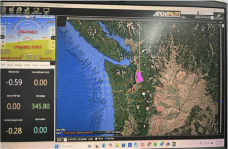
Mission Planner was installed on the laptop to set up ground control. Mission Planner is a ground control software for configuring, controlling, and monitoring autonomous vehicles using ArduPilot or PX4 flight control software, such as Pixhawk. Mission Planner was used for compass and accelerometer calibration, setting up PID parameters, and telemetry monitoring, including vehicle status, position, battery level, GPS data, and sensor readings (Figure 6). This helps monitor the vehicle’s health and performance.
A portable, handmade test stand (Figure 7) was used to experiment with the localization system.
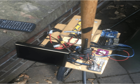
In this prototype, the Ground Station code runs on the Jetson Nano, which is mounted on the portable test stand. It communicates with the Pixhawk over USB. GUI selects the initial course before the mission starts. After the mission begins, there should be no user control, and the keyboard and screen should no longer be needed. The Jetson Nano directs the vehicle prototype to travel from waypoint to waypoint.
The program, written to simulate the vehicle’s navigation in a virtual environment, was leveraged to program the vehicle’s navigation in the real world using a Jetson Nano.
The program sets a set of waypoints (using altitude, longitude, and latitude). Once the GPS was locked, the Jetson Nano monitor displayed the details of the first waypoint for navigation. As the tricycle prototype reached each waypoint, the monitor updated with the details of the next waypoint, continuing until the prototype reached the final waypoint.
The test was repeated 10 times by traveling 20 miles in an open area, with checkpoints after every 2 miles, and 10 times by traveling 2 miles in a dense area, with checkpoints after every 1 mile.
%Accuracy was derived by using Root Mean Square Error (RMSE) calculation for each trial.
![\[\text{RMSE} = \sqrt{\frac{1}{N} \sum_{i=1}^{N} \left( e_i \right)^2 }\]](https://nhsjs.com/wp-content/ql-cache/quicklatex.com-c9cf32224f31effe3c9117efd0c5d226_l3.png "Rendered by QuickLaTeX.com")
N=number of trials
ei =Absolute localization error at checkpoint (Difference between estimated GPS point and GPS actual value).
Result
Intra-Vehicle and Inter-Vehicle Communication
| Distance (m) | Baud Rate | Reliability (%) | Avg Latency (ms) | Data Accuracy (%) |
| 1 | 9600 | 100 | 2 | 100 |
| 1 | 57600 | 100 | 2 | 100 |
| 1 | 115200 | 100 | 2 | 100 |
| 5 | 9600 | 100 | 2 | 100 |
| 5 | 57600 | 100 | 2 | 100 |
| 5 | 115200 | 100 | 2 | 100 |
| 10 | 9600 | 100 | 4 | 100 |
| 10 | 57600 | 100 | 3 | 100 |
| 10 | 115200 | 100 | 3 | 100 |
| 15 | 9600 | 100 | 4 | 100 |
| 15 | 57600 | 100 | 3 | 100 |
| 15 | 115200 | 100 | 3 | 100 |
| 20 | 9600 | 98 | 4 | 100 |
| 20 | 57600 | 99 | 4 | 100 |
| 20 | 115200 | 100 | 3 | 100 |
| 25 | 9600 | 97 | 5 | 100 |
| 25 | 57600 | 98 | 4 | 100 |
| 25 | 115200 | 98 | 4 | 100 |
| 40 | 9600 | 96 | 9 | 100 |
| 40 | 57600 | 96 | 8 | 100 |
| 40 | 115200 | 97 | 6 | 100 |
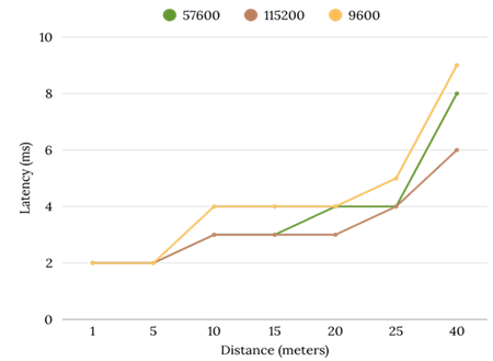
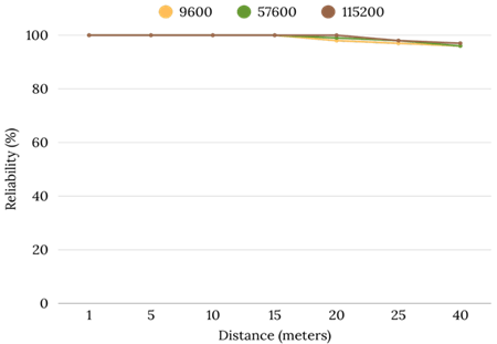
From the test results, wireless communication between two Arduino Due boards, separated by a distance of 20 meters, demonstrates viability for vehicle-to-vehicle communication in vehicle platooning applications. The highest latency at 20 meter was 4 milliseconds (9600 and 57600 baud rate), which is well within the threshold for such applications (Figure 8). Notably, a baud rate of 115200 yielded 100% reliability and accuracy at this distance (Figure 9), whereas lower baud rates did not maintain complete reliability.
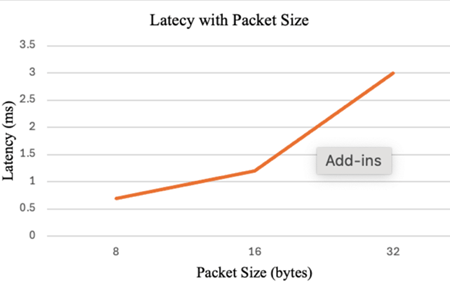
It was also observed (keeping the same baud rate and distance) that latency increases with packet size (Figure 10). A packet size of 32 bytes (sufficient to handle vehicle platooning) exhibits the highest latency of 3 milliseconds at a 115200 baud rate, keeping nodes 20 meters apart.
These tests were conducted indoors in a static environment. Performance parameters, such as latency and reliability, are expected to differ in a real-world scenario.
Localization And Path Navigation of A Vehicle
In the initial run, navigation was about 95% accurate for the short distance. However, it was giving only about 80-85% accuracy in the long-distance run.
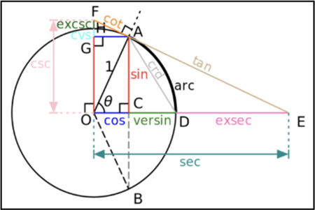
The system had this inaccuracy because the distance was calculated based on the assumption that the Earth is flat. The Python script was revised to calculate the distance using the Haversine Formula, which calculates the distance on a sphere (Figure 11)60.


Result after revising the algorithm
Test 1
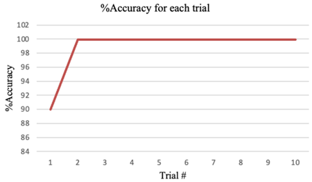
This test was conducted in an open area by traveling 20 miles, with checkpoints every 2 miles (Figure 12).
Result after revising the algorithm
Test 1
This test was conducted in an open area by traveling 20 miles, with checkpoints every 2 miles (Figure 12).
| Trial # | RMSE (meter) | %Accuracy |
| 1 | 1.25 | 90% |
| 2 | 1.09 | 99.9% |
| 3 | 0.88 | 99.9% |
| 4 | 1.09 | 99.9% |
| 5 | 1.04 | 99.9% |
| 6 | 1.09 | 99.9% |
| 7 | 0.91 | 99.9% |
| 8 | 0.93 | 99.9% |
| 9 | 1.05 | 99.9% |
| 10 | 0.93 | 99.9% |
Test 2
This test was conducted in a dense area (covered by large cedar trees) by traveling 2 miles with a checkpoint every 1 mile (Figure 13).
| Trial # | RMSE (meter) | %Accuracy |
| 1 | 26.9 | 98.3% |
| 2 | 26.9 | 98.3% |
| 3 | 26.9 | 98.3% |
| 4 | 26.9 | 98.3% |
| 5 | 26.9 | 98.3% |
| 6 | 26.9 | 98.3% |
| 7 | 26.9 | 98.3% |
| 8 | 26.9 | 98.3% |
| 9 | 27.5 | 98.3% |
| 10 | 27.3 | 98.3% |
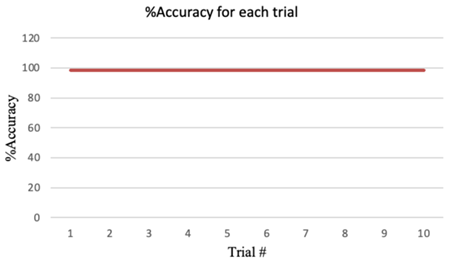
It achieved approximately 99% accuracy in open areas and approximately 98% accuracy in dense areas.
Limited Testing of The Integrated Inter-Vehicle Communication And Localization System
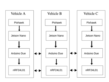
Each experimental vehicle setup is equipped with a Pixhawk flight controller (equipped with GPS), a Jetson Nano, an Arduino Due, and an nRF24L01+ module. The Pixhawk provides real-time GPS-based localization. This GPS data is passed to the Jetson Nano over MAVLink. The Jetson Nano then sends waypoint information to the Arduino Due via an onboard CAN bus. Simultaneously, inter-vehicle communication is handled by each Arduino Due and its nRF24L01+ module. Each Arduino Due sends its vehicle’s state (e.g., current GPS coordinates received from Arduino Due) and broadcasts it over the nRF24L01+ link. The second vehicle’s Arduino receives these packets and relays the state of the first vehicle to its own Jetson for coordination.
In summary, the conceptual dataflow is:
PixhawkA (Vehicle 1) → JetsonA (Vehicle 1)→ ArduinoA (Vehicle 1)→ nRF24L01+ (Vehicle 1)→ (nRF24L01+) (Vehicle 2) → ArduinoB (Vehicle 2).
GPS coordinates were successfully delivered to ArduinoB. However, the initial run showed reduced reliability (~15% less than individual systems) and higher latency (up to ~20 ms). Pixhawk, Jetson Nano, and Arduino Due run asynchronously, causing Synchronization and latency issues. Pixhawk localization messages can be received at different rates than communication messages via nRF24L01+, resulting in unmatched timestamps. To mitigate this, messages can be timestamped, and minimal processing delays can be introduced between messages within modules. Overall system delay (localization to communication response) must be < ~100 ms for safe platooning.
Conclusion
This work presents a low-cost and modular approach to decentralized vehicle platooning utilizing nRF24L01+ wireless communication and a Pixhawk–Jetson Nano-based localization system. The proposed solution emphasizes low cost and accessibility, offering an alternative to more expensive systems such as DSRC and C-V2X. Comparative analysis reports the communication latency, reliability, and localization accuracy of a number of low-cost technologies, demonstrating that, in controlled settings, the nRF24L01+ can sustain an average communication latency of 3 milliseconds and 100% reliability at a baud rate of 115200 when devices are 20 meters apart. After that, however, reliability deteriorated regardless of baud rate. Such a setup is viable for small-scale, short-distance vehicle platoons (e.g., 2–3 vehicles traveling at low speeds).
However, the work also outlines several limitations. Specifically, latency increases in multi-hop environments, which could impact safety-critical coordination. In addition, the current validation is based on controlled environments; large-scale field tests in the real world are still needed to confirm robustness against varying conditions such as interference, node mobility, and environmental noise.
The localization system achieved 99% accuracy in open spaces and approximately 98% accuracy in densely populated areas. GPS satellites will be shielded by dense space, resulting in lower accuracy. In general, this level of accuracy can be utilized to deploy navigation systems in real-world applications. Accuracy fluctuation also indicates that the system is versatile and adaptable to changing environments, which is essential for real-world navigation.
However, the accuracy observed in the experiment is in meters. Whereas, platooning needs accuracy in centimeters. This requires integrating and testing a better GPS module with Pixhawk and Jetson Nano.
Despite these constraints, the results indicate that low-cost platforms can feasibly support decentralized platooning at a basic functional level.
Limitations And Future Work
Inter-vehicle wireless communication
This experimental evaluation was done in controlled and static indoor environments. Although this provides a solid baseline for evaluating the latency and accuracy of the proposed communication system, further tests in outdoor, dynamic, and multi-vehicle environments are necessary to demonstrate scalability, real-time performance, and stability in real-world platooning conditions. This experiment will be extended to multi-vehicle outdoor settings in the future phase of this research. Additionally, performance under interference, dynamic mobility, and vehicle-to-vehicle handover will be evaluated to benchmark against standardized technologies such as DSRC and C-V2X. In a previous study, the nRF24L01+ showed slight variations in performance across different environments, maintaining short, reliable communication distances with 0% error rates and achieving a high effective communication rate. This makes it ideal for high-frequency, low-latency applications that prioritize fast message exchanges in short ranges, potentially suitable for critical safety messaging62.
Cybersecurity measures are not implemented in this phase. The nRF24L01+ module lacks built-in encryption and authentication, making it vulnerable to common wireless threats, including spoofing, eavesdropping, replay attacks, and denial-of-service (DoS) attacks.
| Threat Type | ISO 21434 Requirement | Current System Status |
| Spoofing | Identity verification and authentication | No authentication or ID verification |
| Eavesdropping | Confidentiality via encryption (e.g., AES-128) | Unencrypted transmission |
| Replay Attack | Use of nonces/timestamps to ensure freshness | No freshness check or replay prevention |
| Denial of Service | Resilience strategies (timeouts, fallback logic) | Basic timeouts; no DoS-specific handling |
| Integrity Violation | Message integrity via MAC/hashing | No integrity validation |
| Key Management | Secure storage and distribution of crypto keys | Not yet implemented |
The next phase of this research will involve incorporating light cryptographic protocols into the nRF24L01+ communication system. Cryptographic protocols, such as AES-128 encryption and SipHash message authentication, will be considered for providing secure communication, and nonce-based replay protection mechanisms will be incorporated. A fallback logic system and multi-path redundancy will also be designed to provide improved resistance to denial-of-service attacks. All these incorporations will be made in accordance with ISO/SAE 21434 standards, addressing vulnerabilities as specified in the Threat and Risk Assessment (TARA) framework.
The current system also lacks implementation to maintain string stability. String stability means that disturbances (speed or spacing errors) attenuate rather than amplify along the vehicle chain. This property is critical for safety and efficiency: only a string-stable platoon can safely maintain short gaps and achieve optimal fuel and throughput.
In future work, the following theoretical frameworks will need to be evaluated for the implementation of string stability.
Consensus-based control – A Distributed (consensus) control strategy where each vehicle adjusts its state (velocity/spacing) based on local information to converge with the platoon. Such consensus-based controllers can be designed to enforce string stability explicitly by incorporating stability constraints into the control law.
Local V2V-only communication – Each vehicle communicates only with its immediate predecessor (or nearest neighbors) rather than relying on a centralized broadcast. This local V2V topology simplifies the network but makes string stability highly sensitive to delays. In practice, this means our consensus controller must be robust: it will only attenuate upstream disturbances if the local V2V link is high-speed and reliable.
Given the safety‐critical nature of vehicle platooning, the system design must explicitly account for common failure modes and include basic fail-safe measures. Typical failure modes in wireless platooning include lost or corrupted messages (e.g., packet drops or interference), power interruptions, sensor or actuator failures, and software faults. To mitigate these, standard fault-tolerance strategies will be evaluated and implemented in future research work. For example, a watchdog timer running on each controller can detect if the software hangs or stops sending updates. On timeout, it forces a safe shutdown or reset. Similarly, heartbeat/status messages exchanged periodically between vehicles (and/or a leader) can detect link losses. If a node fails to receive heartbeats within a predefined interval, it should assume the communication has failed and command an emergency brake or halt. Basic timeout and retransmission logic should be implemented in the radio protocol to address occasional packet loss by resending messages if acknowledgments are not received within a short period.
To further evaluate the robustness of the Enhanced ShockBurst (ESB) protocol in real-world conditions, the following testing will simulate adverse network conditions by using controlled packet loss. Packet drops scenarios (e.g., 5%, 10%, and 20%) will be simulated by utilizing either software-based packet loss injection tools or physical testbed setups with RF (Radio Frequency) interference sources. These tests are necessary to evaluate ESB’s automated acknowledgement and retransmission features in response to degradation in communication quality in real-life scenarios.
Overcoming the 6-pipe limit on nRF24L01+ typically involves software techniques. By either reusing pipes with address tags (as in “multi-network” protocols), structuring nodes into a routed tree/mesh (e.g., RF24Network), or time-multiplexing transmissions, practitioners have connected dozens to hundreds of nodes. These techniques have been demonstrated in open-source projects and academic experiments, often with performance data. For example, software-addressed networks have been tested with up to 255 virtual nodes, and hierarchical mesh networks have been run with dozens of Arduinos15,63,64. This can be implemented in the future phase of the project if it is decided to handle communication involving more than six vehicles.
Furthermore, the following options can be considered to enhance scalability and reliability in the nRF24L01+ wireless communication system for larger vehicle platoons.
- Implement a multi-hop network topology:
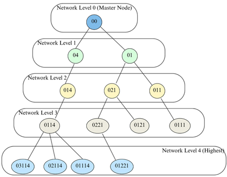
The RF24Network library can be used to create a hierarchical network configuration. In this configuration, messages can be relayed through intermediate nodes, effectively increasing the communication range and helping other vehicles. Each node can communicate with its child and parent nodes, hence facilitating efficient message routing within the network (Figure 14)65.
- Optimize antenna and transmission settings:
- High-gain antennas can be used to increase signal strength and extend the range of communications.Data rate adaptation, by reducing the data transmission rate (e.g., to 250 kbps), can increase the communication range because lower rates are less susceptible to interference66.
- Provide a stable power supply to the nRF24L01+ modules. Inserting a capacitor (e.g., 10 µF) across the power input can help reduce voltage fluctuations and enhance performance.
- Use Radio Environment Maps (REM):
Include REMs to identify and select optimal channels based on environmental interference. This improves dynamic frequency selection, reducing interference for assured communication under varying conditions67.
Localization System
Research suggests that using RTK GNSS, centimeter-level accuracy is consistently achievable in dynamic outdoor conditions68.Pixhawk can be integrated with RTK (Real-Time Kinematic) GNSS, which provides centimeter-level accuracy.
Acknowledgement
I am grateful to Professor Tyler Folsom (School of STEM, University of Washington, Bothell, USA) for letting me use the devices for this research and for sharing the idea that inspired it.
References
- Dubey, S., Sharma, I., Mishra, S., Cats, O., & Bansal, P. (2021). A General Framework to Forecast the Adoption of Novel Products: A Case of Autonomous Vehicles. ArXiv.org. http://arxiv.org/abs/2109.06169 [↩]
- Sarker, A., Qiu, C., & Shen, H. (n.d.). A Decentralized Network with Fast and Lightweight Autonomous Channel Selection in Vehicle Platoons for Collision Avoidance. Retrieved June 27, 2025, from https://www.cs.virginia.edu/~hs6ms/publishedPaper/Conference/2016/Platoon-Shen-MASS16.pdf? [↩]
- Ralf, E., Felix, R., & Michael, R. (2025). Decentralized coordination of platoons – A conceptual approach using deep reinforcement learning. Transportation Research Procedia, 82(0). https://trid.trb.org/View/2493196? [↩]
- Trinh, H. T., Bae, S.-H., & Tran, D. Q. (2022). Deep Reinforcement Learning for Vehicle Platooning at a Signalized Intersection in Mixed Traffic with Partial Detection. Applied Sciences, 12(19), 10145. https://doi.org/10.3390/app121910145 [↩]
- Lee, G., & Jung, J. (2021). Decentralized Platoon Join-in-Middle Protocol Considering Communication Delay for Connected and Automated Vehicle. Sensors, 21(21), 7126. https://doi.org/10.3390/s21217126 [↩]
- CAN specification 2.0, Part A. (n.d.). Retrieved June 28, 2025, from https://www.port.de/fileadmin/user_upload/Dateien_IST_fuer_Migration/CAN20A.pdf? [↩] [↩]
- Falch, M. (2025, January). CAN bus explained – a simple intro (2021). CSS Electronics. https://www.csselectronics.com/pages/can-bus-simple-intro-tutorial [↩]
- (n.d.). https://www.mistralsolutions.com/blog/nvidia-jetson-modules-use-cases-part-2/ [↩]
- Technical documentation. (2025). Nordicsemi.com. https://docs.nordicsemi.com/bundle/nRF24L01P_PS_v1.0/resource/nRF24L01P_PS_v1.0.pdf [↩] [↩] [↩] [↩] [↩] [↩] [↩] [↩] [↩] [↩] [↩] [↩]
- Technical documentation.
(2025). Nordicsemi.com.https://docs.nordicsemi.com/bundle/nRF24L01P_PS_v1.0/resource/nRF24L01P_PS_v1.0.pdf [↩] - Bustamante, M. V., Arteaga, J. G., Vera, C. Y., Aldrin Reyes Narváez, & Molina, H. B. (2024). Communication System Comparison of IoT Applications Using Custom-Designed Antennas: A Basic Experimental Study. 16–16. https://doi.org/10.3390/engproc2024077016 [↩] [↩]
- Martínez, A., Cañibano, E., & Romo, J. (2020). Analysis of Low Cost Communication Technologies for V2I Applications. Applied Sciences, 10(4), 1249. https://doi.org/10.3390/app1004124 [↩]
- Saha, H., Mandal, S., Mitra, S., Banerjee, S., & Saha, U. (2017). Comparative Performance Analysis between nRF24L01+ and XBEE ZB Module Based Wireless Ad-hoc Networks. International Journal of Computer Network and Information Security, 9(7), 36–44. https://doi.org/10.5815/ijcnis.2017.07.05 [↩]
- Martínez, A., Cañibano, E., & Romo, J. (2020). Analysis of Low Cost Communication Technologies for V2I Applications. Applied Sciences, 10(4), 1249. https://doi.org/10.3390/app10041249 [↩] [↩]
- Saha, H., Mandal, S., Mitra, S., Banerjee, S., & Saha, U. (2017). Comparative Performance Analysis between nRF24L01+ and XBEE ZB Module Based Wireless Ad-hoc Networks. International Journal of Computer Network and Information Security, 9(7), 36–44. https://doi.org/10.5815/ijcnis.2017.07.05 [↩] [↩] [↩]
- EBYTE. (2022). Technical characteristics:NRF24L01 short-range wireless communication Chip_Industry dynamics_Blog_. Cdebyte.com. https://www.cdebyte.com/news/1007 [↩]
- EBYTE. (2022). Technical characteristics:NRF24L01 short-range wireless communication Chip_Industry dynamics_Blog_. Cdebyte.com. https://www.cdebyte.com/news/1007 [↩]
- Tamang, D., Mugnaini, M., Parri, L., Valerio Vignoli, & Abrardo, A. (2022). Designing a Reliable and Low-Latency LoRaWAN Solution for Environmental Monitoring in Factories at Major Accident Risk. Sensors, 22(6), 2372–2372. https://doi.org/10.3390/s22062372 [↩] [↩] [↩]
- Foubert, B., & Mitton, N. (2020). Long-Range Wireless Radio Technologies: A Survey. Future Internet, 12(1), 13. https://doi.org/10.3390/fi12010013 [↩]
- Alkhayyal, M., & Mostafa, A. (2024). Recent Developments in AI and ML for IoT: A Systematic Literature Review on LoRaWAN Energy Efficiency and Performance Optimization. Sensors, 24(14), 4482. https://doi.org/10.3390/s24144482 [↩]
- Banti, K., Karampelia, I., Dimakis, T., Boulogeorgos, A.-A. A., Kyriakidis, T., & Louta, M. (2022). LoRaWAN Communication Protocols: A Comprehensive Survey under an Energy Efficiency Perspective. Telecom, 3(2), 322–357. https://doi.org/10.3390/telecom3020018 [↩]
- Tamang, D., Mugnaini, M., Parri, L., Valerio Vignoli, & Abrardo, A. (2022). Designing a Reliable and Low-Latency LoRaWAN Solution for Environmental Monitoring in Factories at Major Accident Risk. Sensors, 22(6), 2372–2372. https://doi.org/10.3390/s22062372 [↩]
- Kaur, G., Balyan, V., & Gupta, S. H. (2025). Nature inspired optimization of IoT network for delay resistant and energy efficient applications. Scientific Reports, 15(1). https://doi.org/10.1038/s41598-025-95138-z [↩]
- Fitch, R., & Lal, R. (n.d.). Experiments with a ZigBee wireless communication system for self-reconfiguring modular robots. Retrieved July 4, 2025, from https://static.aminer.org/pdf/PDF/000/352/028/resource_modelling_and_combination_in_modular_robotics_systems.pdf [↩] [↩]
- Gheorghiu, R., & Iordache, V. (2018). Use of Energy Efficient Sensor Networks to Enhance Dynamic Data Gathering Systems: A Comparative Study between Bluetooth and ZigBee. Sensors, 18(6), 1801. https://doi.org/10.3390/s18061801 [↩]
- Haque, K. F., Abdelgawad, A., & Yelamarthi, K. (2022). Comprehensive Performance Analysis of Zigbee Communication: An Experimental Approach with XBee S2C Module. Sensors, 22(9), 3245. https://doi.org/10.3390/s22093245 [↩]
- Haque, K. F., Abdelgawad, A., & Yelamarthi, K. (2022). Comprehensive Performance Analysis of Zigbee Communication: An Experimental Approach with XBee S2C Module. Sensors, 22(9), 3245. https://doi.org/10.3390/s22093245 [↩] [↩] [↩]
- Gheorghiu, R., & Iordache, V. (2018). Use of Energy Efficient Sensor Networks to Enhance Dynamic Data Gathering Systems: A Comparative Study between Bluetooth and ZigBee. Sensors, 18(6), 1801. https://doi.org/10.3390/s18061801 [↩]
- Becker, B., Oberli, C., Zobel, J., Steinmetz, R., & Meuser, T. (n.d.). ESP-NOW Performance in Outdoor Environments: Field Experiments and Analysis. Retrieved July 4, 2025, from https://dl.ifip.org/db/conf/wons/wons2025/1571077625.pdf [↩] [↩] [↩]
- Pasic, R., Kuzmanov, I., & Atanasovski, K. (n.d.). ESP-NOW communication protocol with ESP32. https://doi.org/10.37886/ip.2021.019 [↩] [↩]
- Eridani, D., Rochim, A., Faiz, N., & Cesara. (n.d.). Comparative Performance Study of ESP-NOW, Wi- Fi, Bluetooth Protocols based on Range, Transmission Speed, Latency, Energy Usage and Barrier Resistance. https://doc-pak.undip.ac.id/id/eprint/24998/1/Article_Comparative_Study.pdf [↩]
- Data transmission reliability over ESP-NOW protocol in indoor environment. (2024, December 19). Developer Portal. https://developer.espressif.com/blog/reliability-esp-now/ [↩] [↩]
- Labib, M. I., ElGazzar, M., Ghalwash, A., & AbdulKader, S. N. (2021). An efficient networking solution for extending and controlling wireless sensor networks using low-energy technologies. PeerJ Computer Science, 7, e780. https://doi.org/10.7717/peerj-cs.780 [↩]
- Arena, F., Pau, G., & Severino, A. (2020). A Review on IEEE 802.11p for Intelligent Transportation Systems. Journal of Sensor and Actuator Networks, 9(2), 22. https://doi.org/10.3390/jsan9020022 [↩] [↩]
- Almeida, T. T., Lucas, Ortiz, F. M., Jose, & Luis. (2018). IEEE 802.11p Performance Evaluation: Simulations vs. Real Experiments. https://doi.org/10.1109/itsc.2018.8569676 [↩]
- Petrov, T., Sevcik, L., Pocta, P., & Dado, M. (2021). A Performance Benchmark for Dedicated Short-Range Communications and LTE-Based Cellular-V2X in the Context of Vehicle-to-Infrastructure Communication and Urban Scenarios. Sensors, 21(15), 5095. https://doi.org/10.3390/s21155095 [↩] [↩] [↩]
- Tsai, M.-F., Chao, Y.-C., Chen, L.-W., Naveen Chilamkurti, & Rho, S. (2015). Cooperative emergency braking warning system in vehicular networks. EURASIP Journal on Wireless Communications and Networking, 2015(1). https://doi.org/10.1186/s13638-015-0262-0 [↩] [↩]
- Eduard Zadobrischi, & Ștefan Havriliuc. (2024). Enhancing Scalability of C-V2X and DSRC Vehicular Communication Protocols with LoRa 2.4 GHz in the Scenario of Urban Traffic Systems. Electronics, 13(14), 2845–2845. https://doi.org/10.3390/electronics13142845 [↩] [↩] [↩] [↩]
- Manshaei, M., Krunz, M., & Yousseef, A. (n.d.). Performance Evaluation of DSRC and C-V2X Coexistence in the 5.895-5.925 GHz Spectrum. https://wicon.arizona.edu/sites/default/files/2024-07/ICNC2024_V2X.pdf [↩]
- Nardini, G., Virdis, A., Campolo, C., Molinaro, A., & Stea, G. (2018). Cellular-V2X Communications for Platooning: Design and Evaluation. Sensors, 18(5), 1527. https://doi.org/10.3390/s18051527 [↩]
- Rodrigues, R. L., & Santhosh, K. V. (2025). Enhancing safe mobility through V2V communication: a focus on short-range performance with UWB. Deleted Journal, 7(5). https://doi.org/10.1007/s42452-025-06928-z [↩] [↩] [↩] [↩] [↩]
- Juston, M. F. R., & Norris, W. R. (2024). Ad Hoc Mesh Network Localization Using Ultra-Wideband for Mobile Robotics. Sensors, 24(4), 1154. https://doi.org/10.3390/s24041154 [↩] [↩]
- Paszek, K., Grzechca, D., & Becker, A. (2021). Design of the UWB Positioning System Simulator for LOS/NLOS Environments. Sensors, 21(14), 4757. https://doi.org/10.3390/s21144757 [↩]
- Tiemann, J., Friedrich, J., & Wietfeld, C. (2022). Experimental Evaluation of IEEE 802.15.4z UWB Ranging Performance under Interference. Sensors, 22(4), 1643. https://doi.org/10.3390/s22041643 [↩]
- Ridolfi, M., Van de Velde, S., Steendam, H., & De Poorter, E. (2018). Analysis of the Scalability of UWB Indoor Localization Solutions for High User Densities. Sensors, 18(6), 1875. https://doi.org/10.3390/s18061875 [↩]
- Aza, A., Melendi, D., García, R., Pañeda, X. G., Pozueco, L., & Corcoba, V. (2021). Bluetooth 5 performance analysis for inter-vehicular communications. Wireless Networks, 28(1), 137–159. https://doi.org/10.1007/s11276-021-02830-9 [↩]
- Perez-Diaz-De-Cerio, D., Hernandez-Solana, A., Garcia-Lozano, M., Bardaji, A. V., & Valenzuela, J.-L. (2021). Speeding Up Bluetooth Mesh. IEEE Access, 9, 93267–93284. https://doi.org/10.1109/access.2021.3093102 [↩]
- Cortesi, S., Vogt, C., Reinschmidt, E., & Magno, M. (n.d.). ETH Library Latency and Power Consumption in 2.4GHz IoT Wireless Mesh Nodes: An Experimental Evaluation of Bluetooth Mesh and Wirepas Mesh Conference Paper Latency and Power Consumption in 2.4 GHz IoT Wireless Mesh Nodes: An Experimental Evaluation of Bluetooth Mesh and Wirepas Mesh. https://www.research-collection.ethz.ch/bitstream/handle/20.500.11850/631059/rzzknfqfhtyswjqvdvfnkwtdmwnqwjhq.pdf [↩] [↩]
- Rondon, R., Mahmood, A., Grimaldi, S., & Gidlund, M. (2020). Understanding the Performance of Bluetooth Mesh: Reliability, Delay, and Scalability Analysis. IEEE Internet of Things Journal, 7(3), 2089–2101. https://doi.org/10.1109/jiot.2019.2960248 [↩] [↩]
- Hernandez-Solana, angela, Perez-Diaz-De-Cerio, D., Garcia-Lozano, M., Bardaji, A. V., & Valenzuela, J.-L. (2020). Bluetooth Mesh Analysis, Issues, and Challenges. IEEE Access, 8, 53784–53800. https://doi.org/10.1109/access.2020.2980795 [↩]
- [↩]
- Rudenko, R. (2021, August 26). Pixhawk Integration Custom Solutions an Open Source Flight Controller. Inertial Labs. https://inertiallabs.com/custom-solutions-from-pixhawk-integration-an-open-source-flight-controller-2/ [↩] [↩] [↩] [↩] [↩] [↩]
- Kornel Sarvajcz, Ari, L., & Jozsef Menyhart. (2024). AI on the Road: NVIDIA Jetson Nano-Powered Computer Vision-Based System for Real-Time Pedestrian and Priority Sign Detection. Applied Sciences, 14(4), 1440–1440. https://doi.org/10.3390/app14041440 [↩] [↩] [↩] [↩] [↩] [↩] [↩]
- Markovic, L., Kovac, M., Milijas, R., Car, M., & Bogdan, S. (2021). Error State Extended Kalman Filter Multi-Sensor Fusion for Unmanned Aerial Vehicle Localization in GPS and Magnetometer Denied Indoor Environments. ArXiv.org. https://arxiv.org/abs/2109.04908? [↩]
- ArduPilot Documentation — ArduPilot documentation. (n.d.). Ardupilot.org. https://ardupilot.org/ardupilot/ [↩] [↩] [↩] [↩] [↩] [↩] [↩]
- NVIDIA Documentation Hub. (n.d.). NVIDIA Docs. https://docs.nvidia.com/ [↩] [↩] [↩] [↩] [↩] [↩]
- Markovic, L., Kovac, M., Milijas, R., Car, M., & Bogdan, S. (2021). Error State Extended Kalman Filter Multi-Sensor Fusion for Unmanned Aerial Vehicle Localization in GPS and Magnetometer Denied Indoor Environments. ArXiv.org. https://arxiv.org/abs/2109.04908? [↩] [↩] [↩]
- MAVProxy — MAVProxy documentation. (n.d.). Ardupilot.org. https://ardupilot.org/mavproxy/ [↩]
- DroneKit Tutorial — Dev documentation. (2022). Ardupilot.org. https://ardupilot.org/dev/docs/droneapi-tutorial.html [↩]
- Kettle, S. (2017, October 5). Distance on a sphere: The Haversine Formula. Esri Community. https://community.esri.com/t5/coordinate-reference-systems-blog/distance-on-a-sphere-the-haversine-formula/ba-p/902128 [↩]
- Kettle, S. (2017, October 5). Distance on a sphere: The Haversine Formula. Esri Community. https://community.esri.com/t5/coordinate-reference-systems-blog/distance-on-a-sphere-the-haversine-formula/ba-p/902128 [↩]
- Iordache, V., Minea, M., Gheorghiu, R. A., Florin Bădău, Cormoș, A. C., Stan, V. A., Ion Nicolae Stăncel, & Stoica, V. (2024). Integrating Connected Vehicles into IoT Ecosystems: A Comparative Study of Low-Power, Long-Range Communication Technologies. Sensors, 24(23), 7607–7607. https://doi.org/10.3390/s24237607 [↩]
- Alex. (2017, April 10). nRF24 Multi-Network – Allowing for 255 addresses «insideGadgets. Insidegadgets.com. https://www.insidegadgets.com/2013/06/09/nrf24-multi-network-allowing-for-255-addresses/ [↩]
- Arduino Wireless Network with Multiple NRF24L01 Modules. (2018, July 31). How to Mechatronics. https://howtomechatronics.com/tutorials/arduino/how-to-build-an-arduino-wireless-network-with-multiple-nrf24l01-modules/ [↩]
- Optimized RF24Network Layer: Network Layer for RF24 Radios. (2024). Github.io. https://nrf24.github.io/RF24Network/? [↩]
- RTK GNSS/GPS (PX4 Integration) | PX4 Guide (main). (2025). Docs.px4.Io. https://docs.px4.io/main/en/advanced/rtk_gps.html? [↩]
- Dynamic Frequency Selection (DFS). (2020, October 5). Cisco Meraki Documentation. https://documentation.meraki.com/MR/Radio_Settings/Dynamic_Frequency_Selection_(DFS) [↩]
- Tavasci, L., Nex, F., & Gandolfi, S. (2024). Reliability of Real-Time Kinematic (RTK) Positioning for Low-Cost Drones’ Navigation across Global Navigation Satellite System (GNSS) Critical Environments. Sensors, 24(18), 6096. https://doi.org/10.3390/s24186096 [↩]


