
Abstract
This paper is an extensive review of the technological advancements in capillary-fed electrolysis (CFE) for production of hydrogen with special emphasis on the comparison of the Hysata electrolyser with the replication attempts of the Eindhoven University of Technology. The Hysata design has registered unprecedented levels of energy efficiencies of over 98%, with new materials and geometries used for improving the efficiency of the electrolysis process and reducing losses of energy. The Eindhoven prototype, while achieving a more limited efficiency of about 55%, still demonstrates the feasibility of the CFE concept and provides key insights into membrane behavior, capillary flow, and design factors that can guide further improvements.By careful analysis of the electrochemical performance, materials employed, and performance figures of merit reported in the literature, this study identifies the most important parameters governing the efficiency and scalability of CFE systems. Published experimental observations are examined alongside theoretical predictions, emphasizing the need for tuning membrane properties and electrode design. The feasibility of these systems from a cost perspective is also discussed, with guidance on the need for thorough cost-benefit analyses for large-scale implementation. Finally, this research adds to the current body of literature on sustainable production of hydrogen, offering findings that can inform research and development into the technology in the future. In addressing the challenges observed in the Eindhoven design and extending the achievement of the Hysata electrolyzer, the research opens the door for more advanced and economically more viable production of hydrogen technology necessary for addressing global energy needs and mitigating climate change.
Keywords: capillary-fed electrolysis, electrolyzer efficiency, green hydrogen, bubble-free electrolysis, porous separator, low-cost energy, technology scalability.
Introduction
The world is facing a tremendous shift in the energy landscape that is brought about by the imperative need of tackling climate change and addressing escalating energy needs. Energy demands are expected to jump by 50% by the year 2050, posing a new nature of challenge for achieving clean and sustainable supplies of energies1.
Hydrogen, specifically green hydrogen generated from renewable means via the process of electrolysis of water, presents itself as one of the most worthwhile alternatives for doing away with zero-emission fueling. Its applications are diverse, ranging from transport through industries and power generation, setting it as the backbone of next-generation energy systems. Despite this, production through current means of hydrogen is based predominantly on fossil fuels. Therefore, it produces approximately 900 million tons of CO₂ per year2. This huge footprint erodes its environmental benefits and constitutes a significant hindrance for adoption.
To date, barriers remain for economically sustainable production of hydrogen. Water electrolyzers, while mature technology for the production of green hydrogen, are far from optimized for competing with fossil-fuel-based hydrogen production, which is valued at $0.8–2.1 per kilogram against $4–6 per kilogram for green hydrogen in 2022 based on global averages3.
History of water electrolysis
Water electrolysis has evolved significantly in pursuit of economically viable and efficient hydrogen production. The phenomenon was first documented in 1800 by William Nicholson and Anthony Carlisle, who used voltaic piles to decompose water into oxygen and hydrogen. These early systems were rudimentary, exhibiting low energy conversion efficiencies and limited practical utility due to substantial energy losses and a poor understanding of electrode materials.
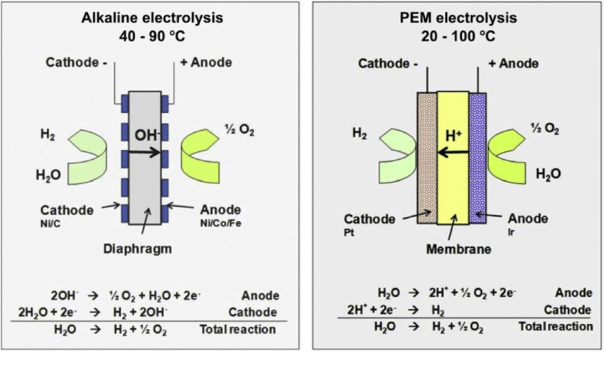
Alkaline electrolysis of water had become the industrial standard for producing hydrogen by the 1920s. This system used nickel or nickel-plated steel electrodes immersed in potassium hydroxide (KOH) electrolyte. The diaphragm, usually of asbestos or equivalent, used to separate the cathode from the anode avoided mixing of gas. Such systems had efficiencies of about 50–60% with losses of energy caused through bubble formation on the surfaces of the electrodes, raising electrical resistance. Though it could be scaled for industrial processes like ammonia synthesis, the process needed large amounts of input energy and posed risks in terms of gas crossover4.
The development of proton exchange membrane (PEM) electrolysis commenced in the 1960s, enabled by the introduction of solid polymer electrolytes such as Nafion by General Electric. The PEM electrolyzers had compact sizes and improved current densities, with efficiencies ranging from 70–80%. Figure (1) illustrates the difference in design and the reaction between alkaline and PEM electrolyzers. The adoption of noble-metal catalysts like platinum and iridium skyrocketed costs, with platinum costing approximately $29,000 per kilogram on average. The dependence on costly membranes further slowed down the general adoption, with PEM electrolyzers confined only to specialized applications like space missions5.
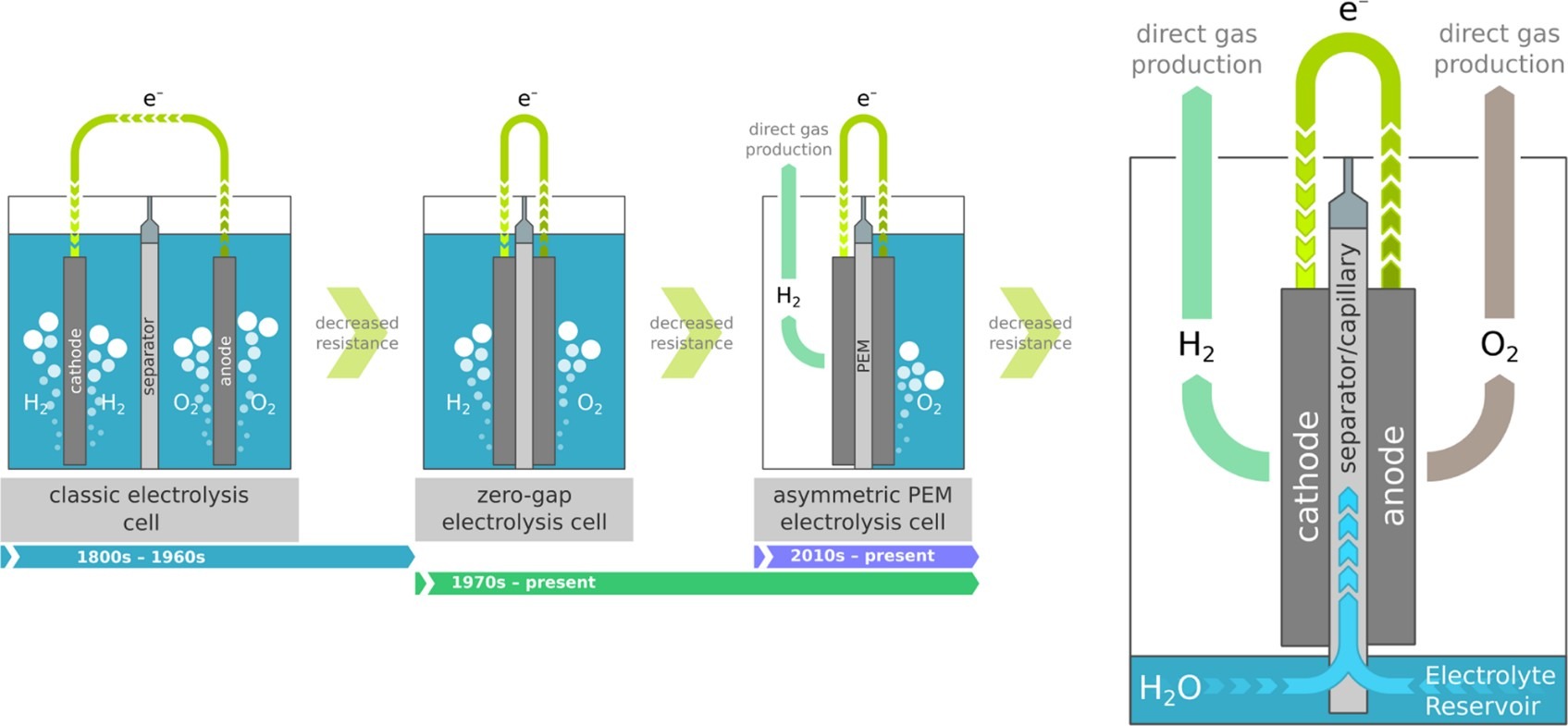
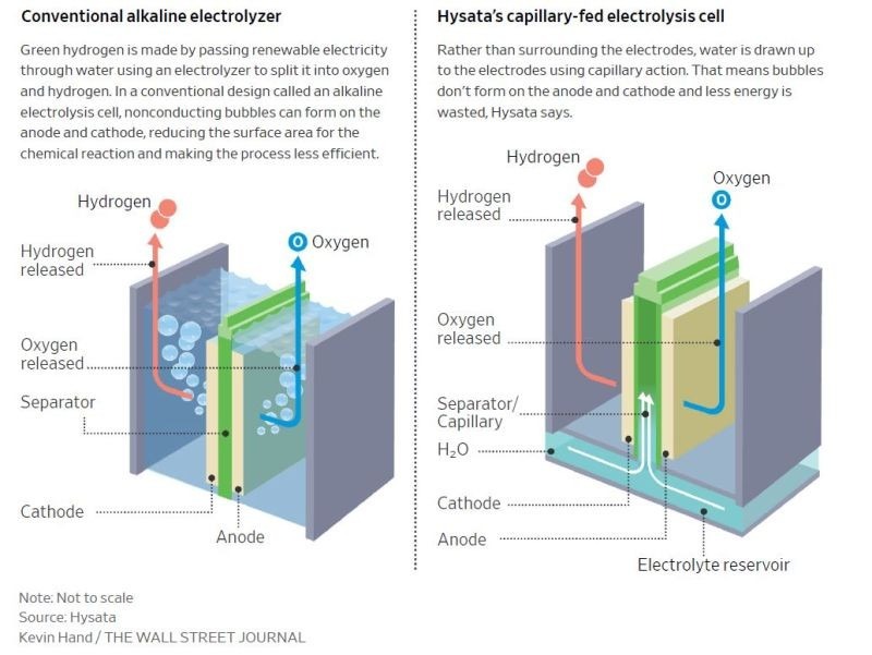
There have been several attempts that have been made in enhancing efficiency and lowering the cost of electrolyzers through redesign or changing the materials used. This paper is a review of literature that discusses the advanced technology of capillary-fed electrolysis (CFE) that is a major breakthrough in the production of green hydrogen since it removes bubble formation on the surface of the electrode which usually lowers active surface, lowering efficiency by 10–20%. Drawing from Hysata’s 2022 technology depicted in figure (2)7, the technology is based on the application of porous membrane which utilizes capillary action for the movement of the electrolyte with abandonment of external pumps and significant losses of energy. With the design of Hysata, it attained the record-high efficiency of 95% with only 40.4 kWh of electricity needed for the production of 1 kg of hydrogen, which is well above existing industrial standards and even target values for the future of relevant bodies such as IRENA.
While there are these promising findings, there are challenges in scaling and replicating this efficiency. For instance, Eindhoven University of Technology tested a CFE prototype applying a polyether sulfone (PES) membrane in a study conducted in 2023. Though chemically stable and mechanically strong, PES lacked consistency in maintaining capillary action and had large ionic resistance, bringing down efficiency to 55%8. However, the existing literature lacks a direct, systematic comparison between these two implementations. The root causes of this performance gap, specifically, which membrane properties and design choices are most critical for success remain unaddressed. This study will tackle such hurdles through determination of the most suitable membrane properties—porosity, pore size, and wettability—to enhance ionic conductivity while ensuring constant electrolyte flow. The study further aspires to create scalable processes for scaling up CFE from laboratory demonstrator levels to industrial production levels, promoting more economical and environmentally friendly production of more sizes of hydrogen on a bigger scale.
Hysata’s Capillary-Fed Electrolyzer Concept
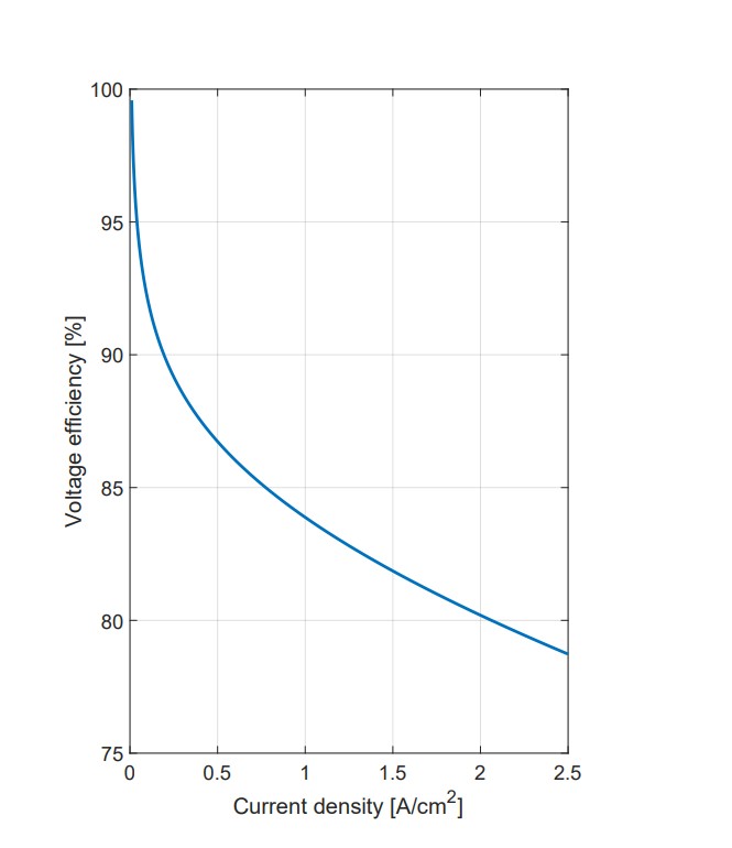
The Hysata electrolyzer fed with the capillary is a unique method of producing green hydrogen, one that overcomes most of the ineffectiveness of conventional electrolyzers while being aligned with global sustainability goals. The design is incredibly energy-efficient, with the cell operating on 1.51 V of voltage over the current density of 0.5 A/cm² with an operating temperature of 85°C. This translates into a whopping 98% efficiency of electricity consumed, requiring only 40.4 kWh of electricity for one kilogram of produced hydrogen. Commercial electrolyzers, for comparison, require approximately 47.5 kWh/kg, pointing out the huge efficiency improvements brought about by the innovative setup.
Green hydrogen is becoming more recognized as one of the most significant tools for the decarbonizing of hard-to-electrify industries like the production of steel, long-distance transport, shipping, and aviation. Outside industrial processes, green hydrogen is used as a vital medium for seasonally storing renewable electricity and as feedstock for chemicals in several processes, pointing out its multi-functional role in a clean-energy economy. The uptake of green hydrogen is, however, affected by multiple obstacles:
A significant barrier to green hydrogen adoption is the high Levelized Cost of Hydrogen (LCOH), which currently makes it non-competitive with fossil fuel-based methods. The primary contributors to this include high CAPEX, from significant initial investments in electrolyzer infrastructure and related technologies, and high OPEX, where operational expenses are driven by energy inefficiency and the cost of renewable electricity.
The energy requirements are also a key factor. State-of-the-art water electrolysis technologies demand approximately 53 kWh of electricity to produce 1 kg of hydrogen, which has an energy value of 39.4 kWh when measured using its Higher Heating Value (HHV)9. This translates to an efficiency of about 83% (HHV) under typical operating conditions.2.1. Global Efficiency Targets.
To improve the viability of green hydrogen, efficiency gains are essential. The International Renewable Energy Agency (IRENA) has ambitious targets for 2050 of bringing down the energy required for producing hydrogen to less than 42 kWh/kg of hydrogen produced. Reducing the LCOH this far would considerably bring down the cost of producing green hydrogen economically, while lessening the environmental impact of production as well.
Capillary-Fed Electrolysis (CFE) Design and Mechanism
The Hysata capillary-fed electrolyzer employs a novel approach that eliminates many of the inefficiencies associated with traditional flow-based systems:
- Design Innovations: The system’s core is a porous, hydrophilic separator that facilitates the flow of water through a capillary action instead of pumps with extensive energy requirements. The pore size of the PES membranes controls the flow rate and the highest height a liquid will be able to flow through the action of capillarity, narrow pore size will indicate more height the liquid will be able with less flow rate, while in turn this will result in lower flow rate with improved height the liquid will be able to cover. This is even more clear from the equation for height h of liquid column according to Jurin’s law10:
![\[h = \frac{2\gamma \cos\theta}{\rho g r}\]](https://nhsjs.com/wp-content/ql-cache/quicklatex.com-65e80de753a28f4239c0d3d647890c79_l3.png "Rendered by QuickLaTeX.com")
Where γ is the liquid-air surface tension, θ is the contact angle, ρ is the density of the liquid, g is the local acceleration due gravity and r is the radius of the capillary. The equation clearly shows that for a higher r, a lower h can be expected, and vice-versa11
– The separator is partially immersed in a water reservoir, initiating upward and in-plane electrolyte flow to the electrodes.
– Porous gas diffusion electrodes are positioned on either side of the separator, facilitating efficient electrochemical reactions.
- Operational Mechanism: The electrolyte is delivered to the electrodes via capillary forces, ensuring a thin and uniform liquid layer for optimal electrolysis. The design as shown in figure (3) minimizes bubble formation during electrolysis, allowing hydrogen and oxygen gases to migrate directly into designated collection chambers without resistance.
Efficiency and Simplification in Hysata’s Capillary-Fed Electrolyzer
The Hysata capillary-fed electrolyzer incorporates various efficiency and design enhancements that improve performance while also easing the balance-of-plant (BoP) and lowering costs. The advancements demonstrate the capability of this technology for transforming the production of green hydrogen.
Efficiency Advantages
The capillary-fed system prevents the formation of bubbles, which can block catalytic sites, especially in micro-crevices or surface defects on electrodes. By avoiding counteracting water and gas flows, the system enhances mass transport, ensuring a steady and efficient supply of reactants to the catalytic surfaces. The elimination of these bubble-related problems dramatically reduces energy losses associated with transport rate limitations and active-site masking. This directly contributes to the electrolyzer’s high energy efficiency, further lowering operational energy demands.
Simplifications in the Electrolyzer Design
The capillary-fed design eliminates the need for liquid circulation systems such as gas-liquid separator tanks, pipes, pumps, and fittings, which reduces engineering complexity and maintenance requirements. The ability to use air-cooling or radiative self-cooling instead of water-cooled chillers further simplifies the system. Each cell incorporates a small liquid electrolyte reservoir, significantly reducing total water consumption compared to conventional systems. Furthermore, the capillary-fed design inherently avoids unwanted shunt currents—unintended electrical currents that flow through parallel pathways and reduce efficiency in traditional alkaline electrolyzers—thereby ensuring consistent performance. By streamlining the system design and eliminating auxiliary components, the capillary-fed electrolyzer reduces both capital expenditure (CAPEX) and operating expenditure (OPEX).
Simplifications in the Balance-of-Plant (BoP)
The absence of bubbles in the electrolyzer operation simplifies the overall engineering system. This lowers the energy load of added elements and decreases the capital expense of the BoP which includes all of the auxiliary systems and devices needed to assist the primary system operation. CFE cells obviate the necessity for liquid circulation pumps, gas-liquid separators, and water-cooled coolers since there are no liquid-enveloped gas bubbles that need to be removed from it.
Hysata’ method
Capillary-Induced Flow System: A hydrophilic polyether sulfone (PES) separator carries the electrolyte by capillary action in the capillary-fed electrolysis system. The separator is coupled with a 27 wt% potassium hydroxide (KOH) solution equaling a 6 M concentration employed in industrial settings. The water is successfully carried by the capillary action a distance of 18 cm by the operational conditions of ≥80°C and 1 A/cm². A top-placed reservoir may also help to overcome gravity-based limitations.
Electrocatalysts and Performance: The system made use of NiFeOOH as an anode for oxygen evolution and Pt/C as a cathode for hydrogen evolution. The materials provide efficient catalytic behavior in water splitting. The performance tests carried out at 80°C and 85°C showed high durability and low overpotentials in accordance with the efficiency targets of high-performance electrolyzers.
Modeling and Analysis: A transport model based on the modified Hagen-Poiseuille equation provides insights into liquid flow behavior. Porosity, tortuosity, viscosity, and surface tension are the critical parameters. The equation for the flow rate combines these parameters. The predicted liquid transport was experimentally validated, and data was provided for system design optimization.
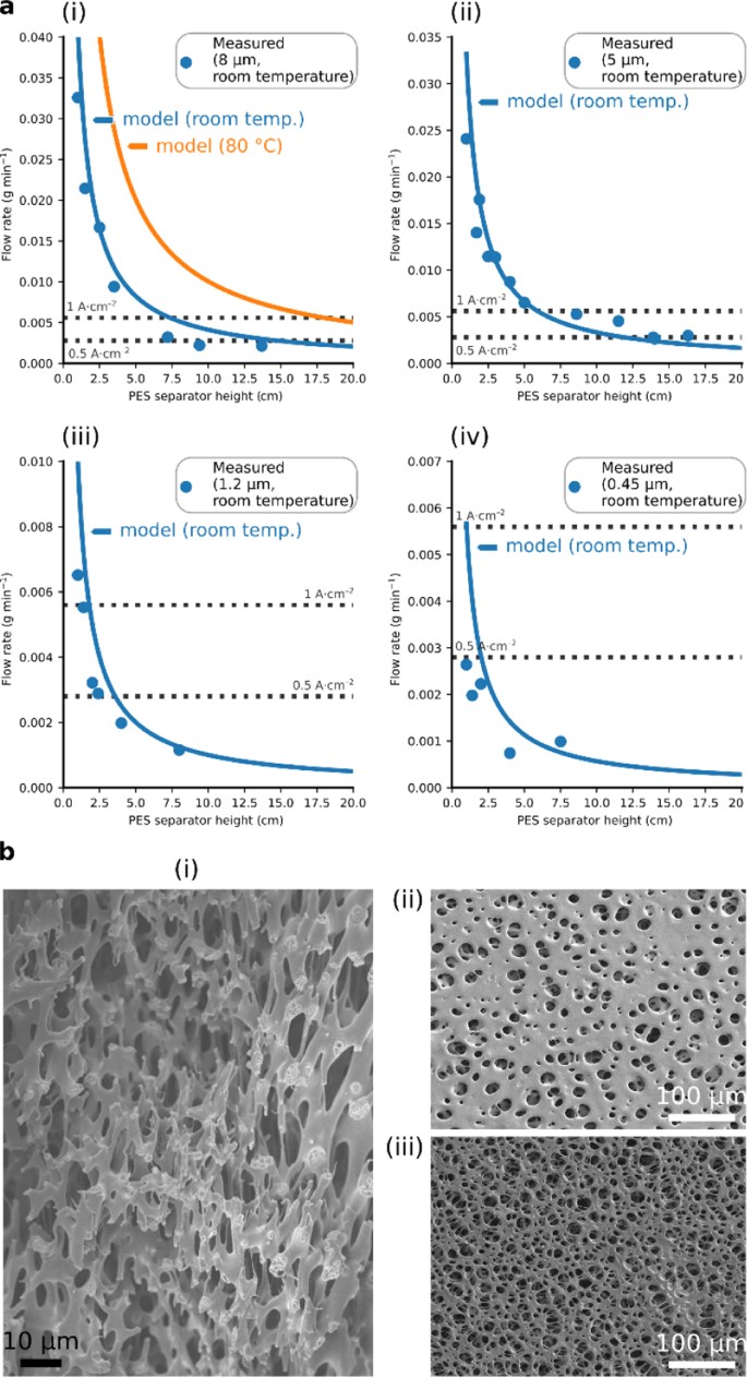
Materials and Equipment Specifications: The materials and equipment specifications included polyethersulfone (PES) filters with pore diameters of 0.03 μm, 0.45 μm, 1.2 μm, 5 μm, and 8 μm. Catalysts used were carbon black, 10% Pt on Vulcan XC-72, nickel chloride (NiCl₂·6H₂O), and iron chloride (FeCl₂·4H₂O). Membrane materials consisted of PTFE dispersion (60 wt%) and Nafion™ dispersion (5 wt%). Other materials included Sigracet™ carbon paper, Zirfon PERL membranes, KOH (90%), and nickel mesh.
Cathode Preparation: A slurry is produced by combining 10% platinum (Pt) on Vulcan XC-72 conductive carbon support, Nafion (proton-conductive binder), deionized water and isopropanol. The mixture is homogenized employing a 10,000-rpm high-speed mixer to provide an even dispersion of materials. The slurry is then applied onto the carbon fiber paper by air brushing to uniformly deposit the catalyst layer. The Pt loading (level of Pt per area) produced is calibrated to 0.5 mg/cm² and strikes a balance between efficiency and cost of materials.
Anode Preparation: The nickel mesh serves as the anode substrate where it is ultrasonically cleaned to remove impurities. It undergoes acid pickling to enhance surface roughness and improve catalyst adhesion. The mesh is then coated with NiFe catalysts through an electrochemical deposition process; Cyclic voltammetry is performed between -1.0 V and -0.2 V to ensure a uniform catalyst layer. Finally, the anode is treated with a PTFE dispersion (10 g/L) to make the surface hydrophobic. This treatment helps manage gas release and maintain stable performance during operation13.
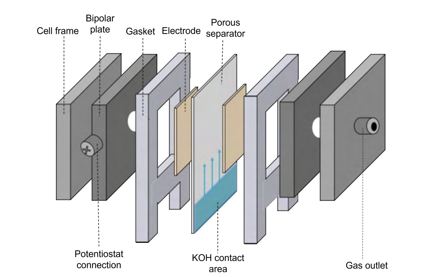
Capillary-Fed Cell Setup: Each cell is equipped with a PES separator that has been soaked overnight in deionized water and 27 wt% KOH for optimal wetting. Nickel gas diffusion bipolar plates with exit holes support the structure. Electrodes are securely pressed against their substrates, and the separator is partially submerged in a KOH electrolyte reservoir. This design eliminates the need for complex circulation systems, simplifying the setup.
Electrochemical Characterization: A BioLogic VMP3 potentiostat is used to analyze the electrolyzer’s performance. This device applies controlled voltages and records current responses, providing detailed electrochemical data. Linear sweep voltammetry (LSV) measures the electrolyzer’s voltage-current relationship by sweeping the voltage between 1.2 and 1.4 V at a rate of 10 mV/s. This technique helps identify the operating voltage needed to sustain specific current densities, which is crucial for determining energy efficiency. To replicate operational conditions and assess thermal stability, the tests are conducted at elevated temperatures of 80°C and 85°C. Galvanostatic electrochemical impedance spectroscopy (GEIS) involves applying a constant current and measuring the resulting impedance across a range of frequencies. This analysis provides insights into various resistance components, including ohmic resistance from materials and connections, and charge transfer resistance, which reflects the efficiency of catalytic reactions at the electrode surfaces. Additionally, GEIS offers valuable information on electrode kinetics, aiding in the refinement of materials and configurations to minimize energy losses.
Results of the Hysata Capillary-Fed Electrolyzer
The Hysata capillary-fed electrolyzer demonstrates groundbreaking advancements in hydrogen production, with notable improvements in efficiency, energy consumption, and system design. These results position it as a competitive alternative to traditional electrolyzers, addressing key industry challenges.
Faradaic and Energy Efficiency
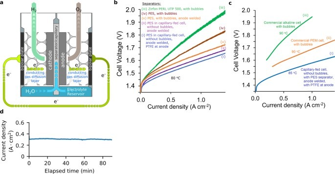
The electrolysis was mainly tested at 80 °C and also at 85 °C for a comparison with industrial systems. The Hysata system demonstrated its high efficiency across different operating conditions. At 80 °C and a current density of 1 A/cm², the cell required 1.59 V (with PTFE) and 1.61 V (without PTFE). When operated at 85 °C and a lower current density of 0.5 A/cm², the cell voltage was 1.506 V. This voltage corresponds to a 98% energy efficiency, calculated using the Higher Heating Value (HHV), and results in a specific energy consumption of 40.4 kWh per kg of hydrogen produced. At a current density of 0.8 A/cm², the system displayed 95% HHV efficiency. At 0.3 A/cm² operation, it achieved an outstanding 100% HHV efficiency, which is the theoretical limit for hydrogen production. These accomplishments correspond to an energy demand of 39.4–41.6 kWh/kg H₂, which exceeds targets by the International Renewable Energy Agency (IRENA) by 2050. This decrease in energy demand makes the use of renewable hydrogen an even more sustainable energy option.
Advanced Separator Characteristics
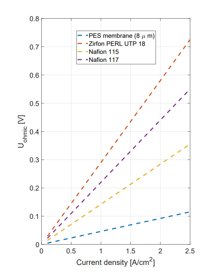
A polyether sulfone (PES) membrane serves as the separator, delivering superior performance through its unique properties14 as shown in Table 17: Comparative measurements revealed that the PES separator had an ionic resistance of 244 mΩ cm² lower than Zirfon PERL UTP 50015, 174 mΩ cm² lower than Nafion 117, and 96 mΩ cm² lower than Nafion 115.
These results indicate that the PES membrane significantly reduces cell voltage requirements, enhancing the overall efficiency of the electrolyzer.
| Separator | Electrolyte | Thickness (µm) | Porosity (%) | Ionic Resistance (mΩ cm²) |
|---|---|---|---|---|
| PES (8 µm) | 27 wt% KOH | 140 | 80 | 46 |
| Zirfon PERL UTP18 | 30 wt% KOH | 500 | 55 | 290 |
| Nafion 11519 | Hydrated | 125 | 0 | 142 |
| Nafion 11719 | Hydrated | 183 | 0 | 220 |
With an average pore size of 8 µm and 80% porosity, the PES membrane supports efficient capillary action and high ionic conductivity as shown in figure 5 which demonstrates its flow rates.
Performance Metrics and Stability
Under testing conditions at 80 °C, the electrolyzer demonstrated exceptional performance: With PTFE-enhanced anodes, it required 1.59 V to achieve 1 A/cm². Without PTFE, the voltage slightly increased to 1.61 V.When tested at a higher temperature of 85 °C, it achieved 0.5 A/cm² at only 1.506 V, equating to 98% HHV energy efficiency with an energy consumption of 40.4 kWh/kg H₂. Stability tests showed that the electrolyzer is strong. It maintained good performance for 30 days at room temperature and for shorter times at higher temperatures. This durability highlights its potential for long-term use in industrial settings.
Enhanced Cell Design and Materials
The cell design incorporated innovative materials and configurations to optimize performance. The polyether sulfone separator reduced ionic resistance and improved capillary flow. Meanwhile, nickel bipolar plates integrated with gas diffusion layers and gas release holes provided structural stability and efficient gas management.
The electrodes further enhanced efficiency: The anode, coated with a NiFeOOH electrocatalyst and PTFE, achieved lower overpotentials and hydrophobicity. Welding the anode to the bipolar plate reduced contact resistance significantly. The cathode, which used a Pt/C electrocatalyst (0.5 mg/cm² Pt loading) on a carbon paper gas diffusion layer, reduced resistance in a reducing environment. The electrolyte, a 27 wt% aqueous KOH solution, supported optimal ionic conductivity and reaction kinetics. Construction modifications, like welding the anode and using precise contact materials, decreased resistance to achieve an 80 mΩ cm² drop in total cell resistance.
Stability and Steady-State Performance
The capillary-fed electrolyzer exhibited outstanding operational stability, maintaining consistent performance for 30 days at room temperature and shorter durations at 80 °C. Its steady-state operation had minimal voltage changes compared to bubbled cells. For example, voltage changes in bubbled cells had a standard deviation (σ) of 1.03 mV, while the Hysata electrolyzer had a much lower σ of 0.14 mV, thanks to its bubble-free design. This stability ensures dependable performance and positions the system as a strong alternative to traditional technologies.
Faradaic Efficiency and Gas Crossover
The electrolyzer achieved a Faradaic efficiency of 99.5 ± 1.3% at 0.35 A/cm², indicating nearly perfect conversion of electrical energy into hydrogen and oxygen gases. Additionally, hydrogen crossover in the anodic oxygen stream ranged from 0.04-0.14 vol%, while crossover in the cathodic hydrogen stream was almost undetectable at 0.001 vol%16. These results highlight the system’s ability to minimize energy losses and gas contamination, which is a critical aspect for safe and efficient hydrogen production.
Comparison with Conventional Electrolysis
The Hysata capillary-fed design outperformed traditional systems: In bubbled cells with Zirfon separators, voltages up to 1.86 V were required for 1 A/cm². In contrast, the Hysata system lowered this to 1.66 V with improved separator and electrode designs. These results show the promise of capillary-fed electrolyzers to meet and even surpass energy efficiency goals. However, the system’s dependency on platinum-group catalysts and highly corrosive potassium hydroxide electrolyte presents challenges for cost-competitiveness and operational safety, underscoring the need to develop transition metal-based catalysts and safer electrolyte management systems. Addressing these issues is key to providing a more affordable and straightforward way to produce hydrogen than traditional alkaline and PEM electrolyzers.
Capillary Fed Electrolyzer design by Eindhoven University
The Hysata demand for a huge efficiency up to 98%, and design innovations put into the forefront of this technology, making the production of hydrogen new and exciting. But producing very-high efficiencies also represents a series of challenges.
Researchers from Eindhoven University of Technology began a project to replicate the Hysata capillary electrolyzer, a new method that uses capillary action for enhanced electrolysis. The project aims to analyze the CFE cell for its performance and scalability in an industrial setting. With design, modeling, and experimental validation of the CFE cell, the investigations address principal problems of hydrogen production, such as energy efficiency and current density. The following chapter will give a detailed insight into the design considerations and approaches employed for the development of the CFE cell8.
Design Overview
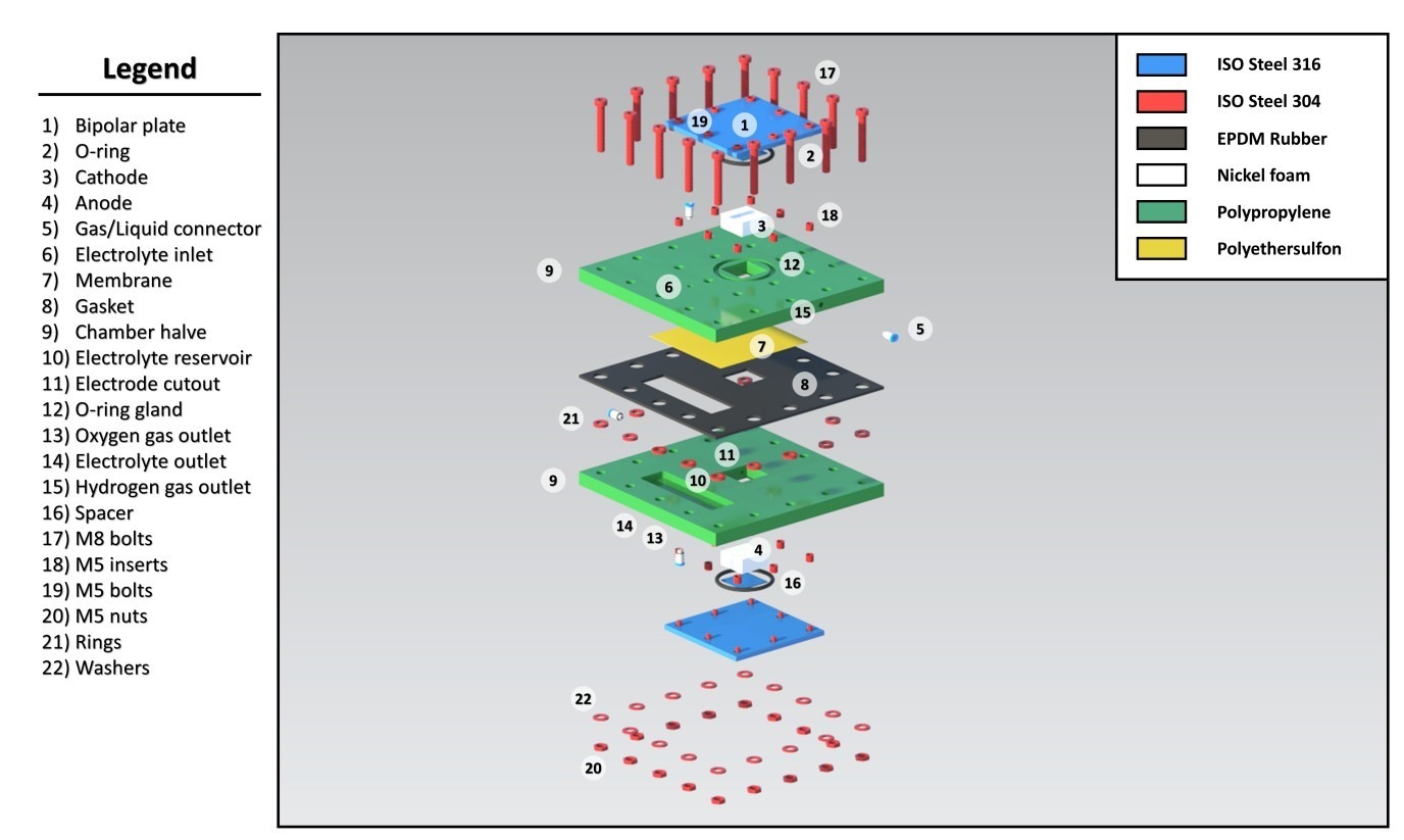
Chamber: The chamber of the Capillary-Fed Electrolysis (CFE) cell is designed to hold the electrolyzer components, ensuring efficient gas and electrolyte flow while minimizing leakage. The chamber is made out of polypropylene (PP) given its excellent chemical resistance and stability under operating condition. The chamber measures 100 mm x 100 mm x 50 mm, which conveniently accommodates electrodes and the electrolyte reservoir.
Face Sealing: The face sealing plays an important role in the design of the CFE cell as it prevents leakage of gases and electrolyte that would otherwise diminish the cell efficiency or even the safety. Different sealing methods were used, including gasket seals on the rear of the cell generated by EPDM (Ethylene Propylene Diene Monomer) rubber gaskets to allow a tight fit that will hold under operational pressures, and adhesive seals used inside the cell with silicone-based adhesives, which serve as reinforcements to the seal against attack from the electrolyte and gases produced by the electrolysis. Face sealing at the rear sides of the cell features grooves for sealing materials, ensuring a secure fit, with sealing effectiveness rigorously tested under pressures up to 2 bar to confirm there is no leakage. Face sealing at the inner part of the cell utilizes materials selected based on their compatibility with the 30 wt% KOH electrolyte and the hydrogen and oxygen gases produced during electrolysis, with sealing performance evaluated through pressure tests and long-term use assessments to ensure durability.
Electrode: The electrodes have been optimized in design so as to provide maximum surface area needed for electrochemical reactions while still maintaining sufficient structural integrity. Each electrode measures 33 mm x 33 mm x 1 mm. There is focus on selecting electrode materials in order to attain optimum conductivity and catalytic properties, which is why nickel foam is chosen for its high surface area and conductivity, thus leading to better performance.
Bipolar Plate: The bipolar plate acts as a conductor between two adjacent cells in a stack setup, allowing for even current distribution. The bipolar plate is designed with a thickness of 5 mm, to be fabricated from SAE 304 stainless steel, which resists corrosion within the electrolyzer. Flow channels, measuring 2 mm x 2 mm, are also machined into the plate to allow for the flow of electrolyte and gases, thus improving mass transport and reaction efficiency.
Spacers: Spacers act as setting for fixing the distance between the electrodes and enabling the uniform flow of the electrolyte. The parts are made of PES or polyethersulfone material, which is chemically resistant, and it is about 1 mm thick. The correct placement of spacers is important to avoid short circuiting and to establish perfect flow dynamics within the cell.
Membrane: The CFE cell will use two different commercial PES membranes having average pore sizes of 0.2 and 8 µm, with approximately similar thicknesses ranging from 110 µm to 150 µm17. Nickel foam will protrude a slight amount (0.1 to 0.5 mm) to be compressed in contact with the bipolar plate to ensure suitable conduction. Care must be taken to avoid heavy compression against the membrane as it may block the pores.
The ultimate objectives for designing the CFE cell are for its great energy efficiency from 70-84% and a very high consumption current density of about 1 A/cm² to 3 A/cm². The design addresses various problems concerning leakage, electrolyte transport, and structural integrity of the cell when under operation.
Objective:
The primary goal of Case 1 is to establish a baseline for the performance of the Capillary-Fed Electrolysis cell under standard conditions. This case serves as a reference point for subsequent analyses and comparisons.
Parameters:
- Electrode Area (A_e): 1 cm²
- Electrolyte Concentration: 30 wt% KOH (Potassium Hydroxide)
- Membrane Thickness (L): 1 cm
- Operating Temperature (T): Room temperature, approximately 25 °C
- Current Density (J_con): Targeting 1 A/cm²
Modeling Approach:
Electrochemical Model: It takes into account the overpotential, which is the extra voltage needed above the theoretical voltage to make the electrochemical reaction occur. The theoretical voltage can be calculated using the Nernst equation, while the actual voltage is usually determined from empirical data.
![\[E = E^0- (\frac{RT}{nF}) \ln (Q)\]](https://nhsjs.com/wp-content/ql-cache/quicklatex.com-99ef8b5ba1ee4587353140db8a4e0d58_l3.png "Rendered by QuickLaTeX.com")
Here, E0 is the standard electrode potential, R is the gas constant (8.314 J/(mol·K)), T is the temperature in Kelvin, n is the number of electrons transferred in the reaction, F is Faraday’s constant (96485 C/mol), and Q is the reaction quotient.
Flow Model: This flow model focuses on how the electrolyte behaves inside the membrane. It concentrates on flow rate or Q and its relation to the membrane size and to the electrolyte properties. The flow rate can be formulated as:
![\[Q = A * v\]](https://nhsjs.com/wp-content/ql-cache/quicklatex.com-361207cad211f3d8eb04e3b67fe596b1_l3.png "Rendered by QuickLaTeX.com")
where A is the cross-sectional area of the flow path and v is the velocity of the electrolyte.
Results:
- The model predicts that under the baseline conditions, the cell can achieve a current density of approximately 1 A/cm². This is significant as it indicates the cell’s capability to operate efficiently at a small scale.
- Energy efficiency (η) is dependent on the actual voltage measurement during the process of electrolysis with respect to the theoretical voltage. The efficiency is important in ascertaining the viability of a CFE cell for industrial use.
Challenges Identified:
The model highlights some problems that might occur, such as electrolyte resistance limiting the current density. Resistance varies with concentration of electrolytes and distance ions need to travel through the membrane. Optimum flow dynamics around the membrane is required to make sure the electrolyte arrives at the electrode properly, thus avoiding situations of flooding or dry-out.
Case 2: Increased Electrode Area
Objective:
The second case aims to investigate the effects of increasing the electrode area on the performance of the CFE cell. This is critical for understanding how the cell can be scaled up for industrial applications.
Parameters:
- Electrode Area: Increased from 1 cm² to 11 cm²
- Electrolyte Concentration: 30 wt% KOH
- Operating Temperature (T): Initially at room temperature (25 °C), with considerations for increasing to 80 °C
- Current Density (Jcon): Targeting 1 A/cm²
Modeling Approach:
Electrochemical Model: Like in Case 1, the electrochemical model predicts how well the electrolysis process works. However, With the larger electrode area, the model must account for the higher resistance and potential changes in the overpotential.
Flow Model: The flow model is updated to match the larger electrode area. The flow rate must be enough to meet the higher demand for electrolyte at the bigger electrode surface. The model examines how the flow dynamics change with the increased area and what that means for current density.
![\[J_{con}= \frac{I}{A}\]](https://nhsjs.com/wp-content/ql-cache/quicklatex.com-2cf6f63fb53d50c36009d92c964a4e6b_l3.png "Rendered by QuickLaTeX.com")
where Jcon is the consumption current density, I is the current, and A is the electrode area.
Results:
The model predicts that, while the current density can initially be maintained at 1 A/cm², challenges arise as the electrode area increases. The resistance of the electrolyte goes up. This increase can cause a drop in current density if not managed properly. According to the analysis, a higher temperature of about 80 °C may be required to attain the current density at a larger electrode area. This temperature increase lowers the viscosity of the electrolyte, thereby enhancing its flow and ion transport.
Challenges Identified:
- The increase in electrode area introduces significant challenges related to cell utilization. For instance, while measurements at J_con = 1 A/cm² are possible at smaller heights (up to 12 cm), this capability diminishes with the larger electrode area.
- The model indicates that to reach a current density of 1 A/cm² at an 11 cm² electrode area, the design must include a 1 cm membrane soaking in the reservoir and a 1 cm barrier between the electrode and the electrolyte cutouts. This setup leaves only 1 cm for the electrode height, creating practical design challenges.
- The findings suggest that, while the CFE cell has potential for industrial applications, it will require significant improvements to address issues occasioned by larger electrode areas and their operational conditions.
Case 3: Application to Industrial Geometry
Objective
The objective of Case 3 was to investigate scaling of the Capillary-Fed Electrolysis (CFE) concept for industrial use, particularly with regard to obtaining a consumption current density (Jcon) of 1 A/cm² on a larger electrode area. From here, they wanted to try and identify the problems and constraints affecting the upsizing of the electrode dimensions while maintaining efficient operation.
Parameters
In this case, the area of the electrode was increased to 1 m², which is about the size used for industrial applications. The electrolyte concentration was held constant at 30 wt% KOH, while the temperature was varied to analyze its effect on performance. Key parameters included:
- Electrode Area: 1 m²
- Electrolyte Concentration: 30 wt% KOH
- Operating Temperature: Varied (25 °C to 80 °C)
Modeling Approach
For Case 3, the modelling was based on modification of the previous electrochemical and flow models to accommodate the larger dimensions. The electrochemical model was adapted to estimate the efficiency (η) and current density (Jcon) under the new conditions, however the flow model was amended to evaluate the influence of mass transport restrictions at higher heights. The study concentrated on association between electrode surface area, current density and related problems in operation.
Results
For Case 3, the simulation results indicate that it is extremely difficult to reach the specified current density of 1 A/cm². Initial modeling indicated current densities at practical heights achieved in model experiments could be kept at 0.16 A/cm², further analysis indicated a reduction to 0.11 A/cm² due to strain-related factors and flow limitations. The increased electrode area introduced complexities in maintaining uniform electrolyte distribution, leading to inefficiencies in the electrolysis process.
Challenges Identified
Several critical challenges emerged from the analysis of Case 3:
- Impractical Dimensions: The requirement to achieve a J_con of 1 A/cm² at a 1 m² electrode area necessitated impractical dimensions for the electrodes. For instance, to maintain the necessary height and width ratios, the design would require an electrode with a height of 1 cm and a width of 1 m, which poses significant engineering challenges.
- Inconsistent Flowrates: The analysis emphasized the continuing issue of low flowrates over the large heights that consequently might result in uneven distribution of electrolyte and lowered efficiency.
- Temperature Management: Current density requirements at higher scales necessitated the temperature to go to 80 °C, which added another layer of complexity to the design-from the thermal point of view.
Fluid Analytical Modelling
In this section, the analysis delves into the implications of the findings from the previous cases, particularly focusing on the feasibility of achieving high consumption current densities (Jcon) in practical applications of capillary-fed electrolysis. The primary objective was to critically evaluate the claims made in the literature regarding the ability to sustain a current density of 1 A/cm² under realistic operational conditions.
- Case 1 Recap: In Case 1 analysis, the first aim was to determine the theoretical limit of current density attainable in a capillary-fed electrolysis system. The results have shown that, initially, under practical heights, it was overly hard for a current of 1 A/cm² to be achieved; but this was made more optimistic when the presence of the electrolyte adjustements was considered. It was then suggested that a current density of 0.5 A/cm² could be sustained to a height of 10 cm, and current densities of up to 1 A/cm² probably could be sustained to heights of around 12 cm. This tempered the initial skepticism regarding the concept’s applicability to industrial current densities, suggesting that with the right conditions, significant performance could be achieved.
- Case 2 Recap: The analysis of a larger electrode area in Case 2 provided critical insights into the challenges associated with scaling up the system. It was observed that the anticipated current density experienced a strain-related reduction, dropping from 0.16 A/cm² to 0.11 A/cm² for the designed cell. That in itself brings out the complex challenges while going for the larger dimensions of the electrolyzer, as the larger geometries bring factors into play that diminish efficiencies and performance, such as increased resistance and decreased flow rates of the electrolyte.
- Challenges Identified: The analysis emphasized persistent challenges in achieving the desired current densities in larger geometries. Key issues included:
- Low Flow Rates As the height of the electrolyzer increases, it becomes more challenging to maintain the electrolyte flow to the electrodes. This becomes crucial as the electrochemical reaction requires the continuous supply of the electrolyte to sustain the current density..
- Electrode Design Limitations: The design of the electrodes must accommodate the increased dimensions while still allowing for effective electrochemical reactions. Larger electrodes may require more sophisticated designs to ensure uniform current distribution and minimize localized overheating or depletion of the electrolyte.
- Thermal Management: Increase in currents also possibly means increase in thermal generation within the cell. Managing heat, if this situation arises, is very critical to avoid degrading the cell components and to store in optimal working conditions.
Meeting Hydrogen Production Demands
High-end industrial Proton Exchange Membrane (PEM) electrolyzers are capable of producing significant quantities of high-purity hydrogen daily—up to 450 kg.
- Calculating Cell Requirements: To judge the scaling capability of the designed electrolyzer, this analysis seeks to find out how many cells would be required to produce 1 kg of hydrogen gas within a day. Such a determination is needed to work out the economic and otherwise operational feasibility of the proposed system for the production of hydrogen on an industrial scale.
- Hydrogen Production Rate: The production rate of hydrogen depends mainly on the current density and the efficiency of the electrolyzer. For instance, if the electrolyzer works at a current density of 1 A/cm², then the total surface area of the electrodes and the amount of operating hours will determine the total hydrogen production.
- Scaling Up: The analysis draws out the importance of designing proper scale to meet high production rates being sought for industrial settings. It asserts that whereas theoretical models may well state certain current densities to be achievable, practicality must adhere to considerations of flow rates, electrode dimensions, and, more broadly, to the design of the system itself.
- Efficiency Considerations: The section also touches on the energy efficiency of the electrolyzer. achieving about 70% energy efficiency is widely accepted as standard in the industry. The efficiency is given as the thermoneutral voltage (U_tn = 1.48V) over the measured current and is thus considered to assess the economic viability of the hydrogen generation method.
- Energy Input vs. Output: The energy input required for electrolysis must be balanced with that energy output, through hydrogen production. The electrolyzer’s efficiency determines the operating cost and overall sustainability of hydrogen production.
- The cell potential: The potential of the cell can be written as the summation of the following contributions from the surface overpotentials18:
![\[Vcell = Ucell + |\eta anode| + |\eta cathode| + |\eta ohmic|\]](https://nhsjs.com/wp-content/ql-cache/quicklatex.com-f7dece2008affc8ce0c6f085596ac58d_l3.png "Rendered by QuickLaTeX.com")
Where Ucell is the contribution from the equilibrium voltage. Which is the potential at equilibrium conditions where there is no current and no concentration gradient to cause irreversibilities18. ηanode and ηcathode are the overpotentials of the anode and cathode respectively, and ηohmic is the overpotential due to the ohmic losses, which can be defined in the context of this cell as the resistances caused by the PES membrane and the bipolar plates
- Impact of Temperature and Concentration: The efficiency can also be influenced by the temperature of the electrolyte and its concentration. Higher temperatures can enhance reaction kinetics, potentially allowing for higher current densities, but they also require careful thermal management to avoid damaging the cell components.
Results
In summarizing the findings from the analysis, several key points emerge:
- Feasibility of High Current Densities: According to the study, high current densities are theoretically realistic but are difficult to attain in practice mainly because of the restriction in flow rate and electrode design. This finding points toward the need for innovative designs and configurations to circumvent such limitations.
- Impact of Scaling: Changes that introduce complexity from small to large industrial operating systems are responsible for performance degradation. Hence, the analysis shows that with the increase of electrode area and height, the current density does not increase in a consistent manner, and thus, the design strategies need to be reconsidered.
- Non-linear Scaling Effects: As the electrode area increases, the behavior of current density becomes more complex. Also, during the design of the electrodes, factors such as resistance, heat generation, and electrolyte flow dynamics need to be considered.
- Need for Further Research: The challenges identified in the analysis call for further exploration and refinement of the electrolyzer design. This includes investigating alternative geometries, materials, and operational strategies that could enhance performance and efficiency.
- Innovative Design Approaches: Future research may focus on developing novel electrode materials that can withstand higher current densities, as well as optimizing the geometry of the electrolyzer to improve electrolyte flow and reduce resistance.
- Industrial Application Viability: Ultimately, the analysis raises questions about the practical application of the proposed concept in industrial settings. While the theoretical models provide valuable insights, the real-world implementation must address the identified challenges to ensure successful hydrogen production.
- Economic Considerations: The economic viability of the electrolyzer design will depend not only on its performance but also on the cost of materials, energy consumption, and maintenance requirements. A comprehensive cost-benefit analysis will be essential for determining the feasibility of large-scale deployment.
Experimental Setup and Procedure
Understanding the performance of the Capillary-Fed Electrolysis (CFE) cell necessitates a crucial experiment. In particular, the section lays out the goals, methods used, and layout of the experiments for reviewing the electrochemical behavior of the cell.
Objectives of the Experiments
Validation of Modeling Predictions: The experiments seek to verify what the modeling section predicted with respect to the actual performance and industrial viability of the CFE concept. It essentially puts to test the theoretical assumptions made and parameters established during the modeling phase.
Critical Assessment of Design Performance: The experiments seek to critically assess performance of CFE cell design which covers determination of critical factors influencing performance and how these factors can be controlled towards better efficiency and current density.
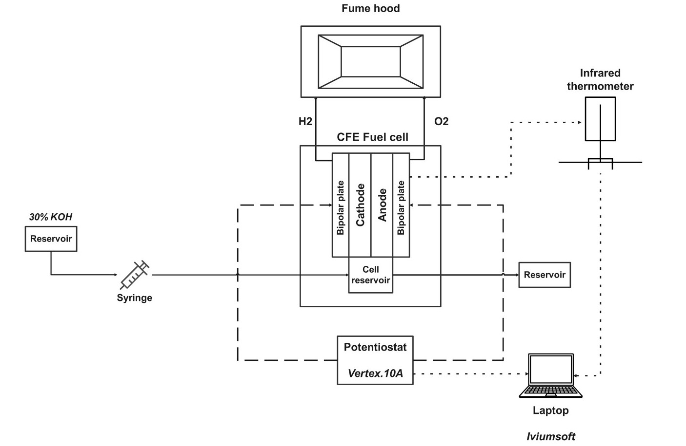
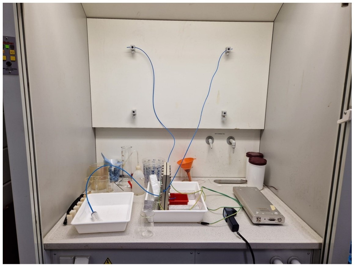
Experimental Configuration
The experimental setup itself is purposely designed for appropriately taking measurements and closely studying the CFE cell’s accurate performance. Some of the key components of the experimental setup are as follows:
- Electrochemical Testing Apparatus: At the heart of the setup stands an electrochemical cell in which the electrolysis is supposed to occur. This cell is designed in such a manner that a controlled current is passed through the electrodes and the voltage may be measured across them.
- Electrodes: The electrodes used for this experiment are selected keeping in view their material nature and surface area. The design calls for considerations of gas evolution at these electrodes with limited resistance in the electrochemical reactions.
- Membrane Selection: The membrane plays a critical role in the CFE cell’s operation. Different membrane types with varying pore sizes (8 μm, 5 μm, and 0.2 μm) are utilized to assess their impact on the flow dynamics and overall performance of the cell. The choice of membrane is crucial for optimizing the capillary action and ensuring efficient electrolyte transport to the electrodes.
- Compression Levels: The experiments involve varying the compression levels applied to the membrane. Two specific compression levels are tested: 0.5 mm and 0.1 mm. This variation is essential to understand how membrane compression affects the flow rate, resistance, and overall efficiency of the electrolysis process.
- Electrolyte Solution: A 30 wt% KOH solution is used as the electrolyte in the experiments. The concentration of the electrolyte is critical for achieving the desired ionic conductivity and facilitating the electrochemical reactions at the electrodes.
Methodology
The methodology employed in the experiments is structured to ensure systematic data collection and analysis. The following steps outline the experimental procedures:
Placement of the Electrochemical Cell: The electrochemical cell is assembled with the chosen electrodes and membrane. All components must be aligned and sealed to avoid leakage of the electrolyte.
Electrolyte Filling: The cell is filled with the 30 wt% KOH electrolyte solution. The filling process is conducted under controlled conditions to avoid introducing air bubbles, which could interfere with the electrochemical reactions.
Two-Electrode Setup: Due to design constraints, a two-electrode rather than a three-electrode configuration is used. The simpler design makes it hard, however, to control the voltage and comprehend the individual behavior of each electrode. The use of a two-electrode setup was chosen mainly because of the needs of the CFE cell design.
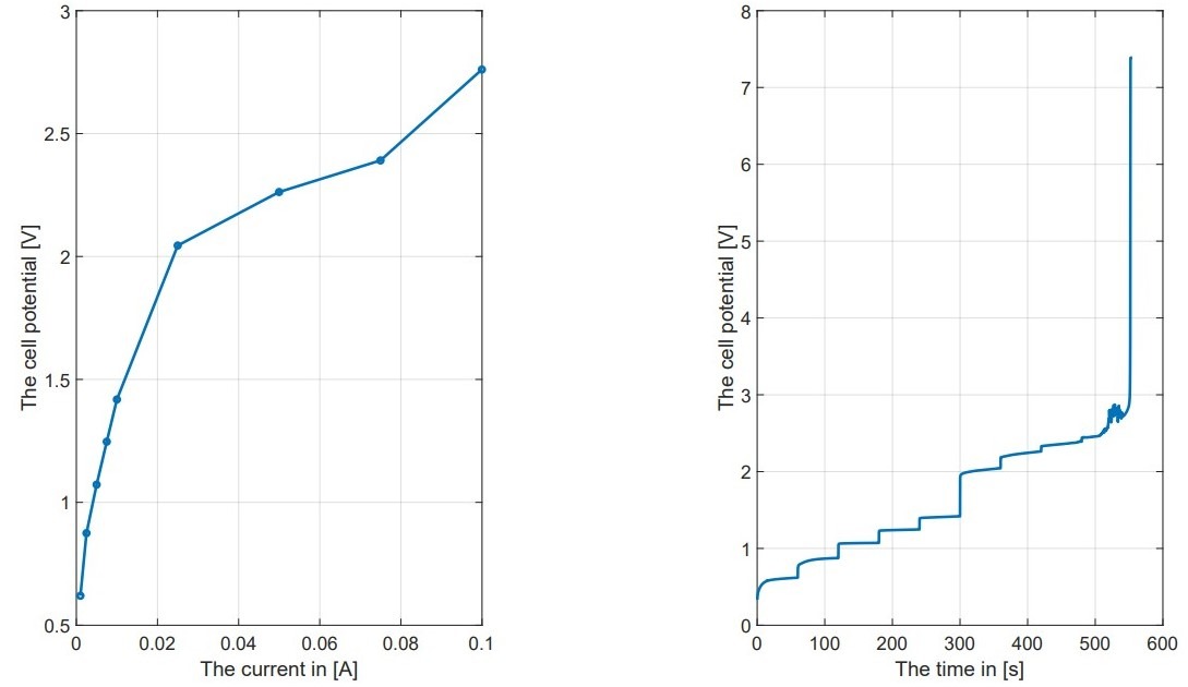
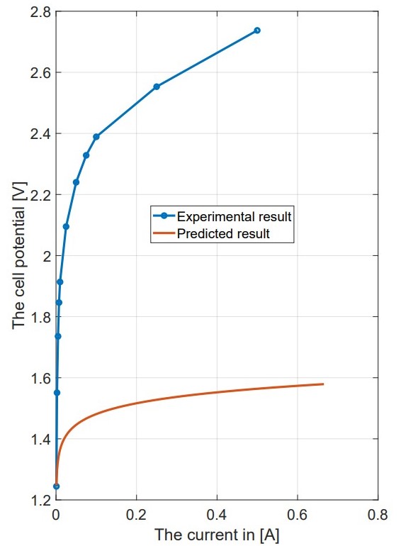
Current Application: The potentiostat applies a controlled current to the cell and voltage of 2.7V at 8 µm. The current is changed systematically such that polarization (I-V) curves and time-dependent potential (V-t) curves are generated. These curves are necessary for studying the electrochemical features of the given cell.
Data Collection: At regular time intervals, voltage measurements are taken as current is applied. Such data collection is so important as it helps calculate overpotential, which is the difference in voltage between the actual voltage and the thermoneutral voltage.
Variation of Parameters: The experiments involve varying with the key parameters, such as the membrane pore size and compression levels, which is to measure their impact on the electrolysis performance. Each combination of parameters is tested multiple times to ensure the reliability of the results.
Analysis of Electrochemical Behavior: The data is studied to analyze the electrochemical behavior of the CFE cell under various operating conditions. This includes studying current density, voltage, and efficiency relationships.
Limitations and Considerations: The absence of reference electrodes in the two-electrode setup is acknowledged as a limitation. While this setup may hinder precise voltage control and limit the understanding of individual electrode behavior, it is obviously necessary for the specific design and experimental goals. Future experiments are recommended to include reference electrodes for improved accuracy.
Experimental Findings
Polarization Curves and Overpotential: The experiments gave polarization curves (I-V characteristics) and V-t curves, which are necessary to understand the electrochemistry of the CFE cell. The polarization curves showed the current applied to the cell versus the resultant voltage, which is then used to calculate the overpotential. The overpotential is an important parameter as it denotes an additional voltage required over and above the thermoneutral voltage to bring on the onset of the electrochemical reaction. It was observed that by changing the membrane pore sizes (8 μm, 5 μm, and 0.2 μm) and varying the compression (-0.5 mm and 0.1 mm), there lies a significant expected influence on the cell performance. The cell seemed to show more potential than the computational potential as shown in the figure.
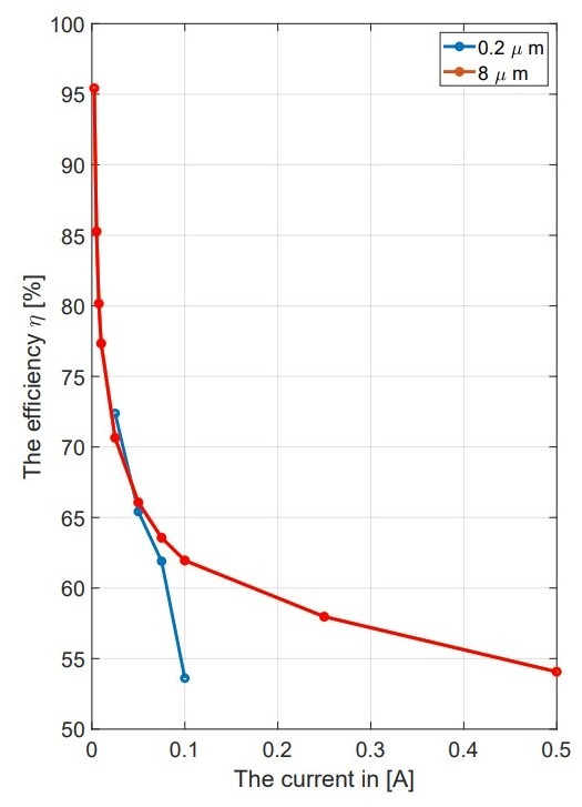
Impact of Membrane Characteristics: The experiments showed that pore size and compression of the membrane are critical elements for the cell performance. For instance, large-pore membranes (8 μm) showed a lower overpotential than those contained smaller pores (0.2 μm) under the same compression conditions19. This suggests that larger pores facilitate better electrolyte transport, thereby enhancing the electrochemical reaction efficiency. Additionally, reducing the compression from 0.5 mm to 0.1 mm resulted in improved performance metrics, indicating that less compression allows for better ion transport and reduced internal resistance.

Consumption Current Density: The maximum consumption current density (Jcon) that the cell could sustain was evaluated. The experiments showed that the cell could maintain a current density of 1 A/cm² under specific conditions, but challenges appeared when trying to increase the electrode area. For instance, increasing the electrode area from 1 cm² to 11 cm² made it hard to keep the desired current density without overheating the system. The experiments revealed that achieving Jcon of 1 A/cm² up to 12 cm using 30 wt% KOH at room temperature is possible, but this ability disappeared with the larger electrode area20.
Challenges with Scaling: The scaling of the CFE cell faced several challenges. As the electrode area and the membrane length or thickness increased, maintaining optimal performance became harder. The experiments showed that while the cell worked well at smaller scales, moving to larger scales needed major changes in design and operating parameters. For example, the requirement for a 1 cm membrane soaking in the reservoir and a 1 cm barrier between the electrode and electrolyte cutouts limited the effective height for the electrode, making the design more complicated for larger applications.
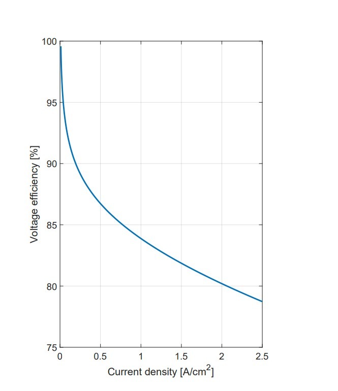
Energy Efficiency Measurements: At lower currents, the cell still needs to overcome a 1.48V barrier to produce hydrogen, which can lead to efficiencies over 100%. Therefore, these data points have been excluded. After these low currents, efficiency drops to about 55% at 0.5A, and then it stabilizes at a more consistent level. However, this level is below the industrialization threshold, as efficiency falls under the desired η = 75% before reaching the current density levels needed for industrial uses.
Comparative Analysis with Modeling: The experimental results were compared to the predictions made during the modeling phase. This comparison was important for checking the model’s accuracy and understanding the differences between theoretical predictions and practical outcomes. The findings showed that while the model provided a good starting point, some real-world factors, like temperature changes and material properties, were not completely considered, resulting in differences in performance metrics.
Discussion and Future Recommendations
This research has analyzed the performance of capillary-fed electrolysis (CFE) cells, demonstrating that membrane properties, such as a pore size of 8 μm and 80% porosity, and compression levels are critical parameters governing ionic resistance and capillary flow, directly impacting the hydrogen production efficiency. The results underscore that optimizing these parameters is the key to achieving the record-high efficiencies demonstrated by the Hysata system. However, to translate this lab-scale potential into a commercially viable technology, CFE must be contextualized within the broader landscape of hydrogen production and its specific challenges must be addressed.
The path forward for CFE involves tackling key limitations also faced by other advanced systems. While CFE achieves superior electrical efficiency (~95-98% HHV), its reliance on platinum-group metal catalysts, even at low loadings of ~0.5 mg/cm², and corrosive 27-30 wt% KOH electrolytes, presents cost and safety hurdles. For perspective, this places CFE in a middle ground: it seeks the high efficiency of Proton Exchange Membrane (PEM) electrolyzers but must overcome PEM’s high cost from using ~1-2 mg/cm² of platinum and iridium.
Simultaneously, CFE must achieve a longer lifespan and better performance than traditional alkaline electrolyzers (50-60% efficiency) while managing a similar corrosive electrolyte. The development of high-performance, non-precious metal catalysts—such as nickel-molybdenum or nickel-iron alloys, which are a primary research focus for Anion Exchange Membrane (AEM) electrolyzers aiming for 70-80% efficiency without precious metals—is therefore just as critical for CFE’s economic case.
Furthermore, the exploration of alternative porous materials extends beyond polyether sulfone (PES). Future research should target membranes with sub-micron pore sizes (0.1-1 μm), porosities exceeding 85%, and engineered surface chemistry to optimize the capillary pressure described by Jurin’s Law. Materials like sulfonated poly(ether ether ketone) (SPEEK) or advanced ceramics could offer superior ionic conductivity (< 50 mΩ cm²) and enhanced chemical stability. This materials innovation is crucial for CFE to maintain its efficiency edge over evolving competitors and to enable operation under more demanding conditions.
Finally, system-level innovations, such as inverting the cell to place the electrolyte reservoir above the membrane, could utilize gravity to augment capillary forces. This may enable operation at even higher current densities (> 2 A/cm²) by ensuring a surplus electrolyte supply, a challenge for many electrolyzer types. When compared to non-electrolytic pathways like methane pyrolysis (which produces CO2-free hydrogen but requires high heat at ~1200°C and yields solid carbon), CFE’s advantage lies in its modularity and compatibility with renewable electricity.
Conclusion
This research has provided a comprehensive analysis of the capillary-fed electrolysis (CFE) technology, highlighting its potential as a transformative approach to hydrogen production. The Hysata capillary-fed electrolyzer has demonstrated remarkable advancements, achieving energy efficiencies of up to 98% and significantly reducing energy consumption to approximately 40.4 kWh/kg H₂. Its innovative design, which utilizes a porous membrane to facilitate capillary action, effectively addresses the challenges of bubble formation and energy losses typically associated with traditional electrolyzers.
In contrast, the Eindhoven University of Technology’s efforts to replicate the Hysata design have revealed both the promise and challenges of implementing CFE technology in real-world applications. While the Eindhoven prototype has shown potential, it has faced limitations in maintaining consistent capillary action and exhibited higher ionic resistance, resulting in reduced efficiency levels around 55%. This underscores the importance of optimizing membrane characteristics and system design to achieve the high performance demonstrated by Hysata.
The comparison between the Hysata and Eindhoven designs illustrates the critical role of material selection and system configuration in the success of CFE technology. Hysata’s approach has set a benchmark for efficiency, while the Eindhoven research highlights the ongoing need for innovation and refinement in membrane technology and electrolyzer design.
| Feature/Aspect | Hysata Capillary-Fed Electrolyzer | Eindhoven University Prototype |
|---|---|---|
| Energy Efficiency | Up to 98% (HHV) | Approximately 55% |
| Operating Voltage | 1.506 V at 85°C for 0.5 A/cm² | 1.48 V for at least 0.5 A/cm² |
| Current Density | Achieved 1 A/cm² at 1.59 V (with PTFE) | Lower current densities due to efficiency issues |
| Energy Consumption | 40.4 kWh/kg H2 | Not specified, but significantly higher than Hysata |
| Temperature Testing | Tested at 80°C and 85°C | Room temperature |
| Membrane Material | Utilizes polyether sulfone (PES) membranes | Also used PES, but faced challenges with ionic resistance |
| Challenges | None specified; design effectively addresses bubble formation | Issues with maintaining consistent capillary action and higher ionic resistance |
| Innovative Design Features | Porous membrane facilitating capillary action | Attempted replication of Hysata design, but with limitations |
| Electrochemical Techniques Used | Linear Sweep Voltammetry (LSV), Galvanostatic Electrochemical Impedance Spectroscopy (GEIS) | Polarization curves (I-V curves) and time-dependent potential (V-t) curves |
| Research Focus | Optimization of materials and configurations for efficiency | Replication of Hysata design and addressing challenges in real-world applications |
| Conclusion | Set a benchmark for efficiency in CFE technology | Highlights the need for further innovation and refinement in membrane technology |
Overall, the findings of this study emphasize the importance of continued research and development in the field of green hydrogen production. By addressing the challenges identified in the Eindhoven design and building upon the successes of the Hysata electrolyzer, future advancements in CFE technology can contribute significantly to the establishment of sustainable and economically viable hydrogen production systems, paving the way for a cleaner energy future.
References
- H. Brugger, W. Eichhammer, N. Mikova, and E. Dönitz, “Energy Efficiency Vision 2050: How will new societal trends influence future energy demand in the European countries?,” Energy Policy, vol. 152, p. 112216, May 2021, doi: https://doi.org/10.1016/j.enpol.2021.112216. [↩]
- S. G. Nnabuife et al., “The prospects of hydrogen in achieving net zero emissions by 2050: A critical review,” Sustainable Chemistry for Climate Action, vol. 2, p. 100024, Jan. 2023, doi: https://doi.org/10.1016/j.scca.2023.100024. [↩]
- A. Ajanovic, M. Sayer, and R. Haas, “The economics and the environmental benignity of different colors of hydrogen,” International Journal of Hydrogen Energy, vol. 47, no. 57, Mar. 2022, doi: https://doi.org/10.1016/j.ijhydene.2022.02.094. [↩]
- K. Zeng and D. Zhang, “Recent progress in alkaline water electrolysis for hydrogen production and applications,” Progress in Energy and Combustion Science, vol. 36, no. 3, pp. 307–326, Jun. 2010, doi: https://doi.org/10.1016/j.pecs.2009.11.002. [↩]
- Á. Hernández-Gómez, V. Ramirez, and D. Guilbert, “Investigation of PEM electrolyzer modeling: Electrical domain, efficiency, and specific energy consumption,” International Journal of Hydrogen Energy, vol. 45, no. 29, pp. 14625–14639, May 2020, doi: https://doi.org/10.1016/j.ijhydene.2020.03.195. [↩]
- V. Gatard, “Alkaline water electrolysis enhanced by radio frequency alternating magnetic field,” Dec. 17, 2021. https://www.researchgate.net/publication/359700003_Alkaline_water_electrolysis_enhanced_by_radio_frequency_alternating_magnetic_field [↩]
- A. Hodges et al., “A high-performance capillary-fed Electrolysis Cell Promises More cost-competitive Renewable Hydrogen,” Nature Communications, vol. 13, no. 1, Mar. 2022, doi: https://doi.org/10.1038/s41467-022-28953-x. [↩] [↩] [↩] [↩]
- Industrialisation of a Capillary-Fed Electrolysis (CFE) cell through design, modelling and experiments,” Research portal Eindhoven University of Technology, 2023. https://research.tue.nl/en/studentTheses/industrialisation-of-a-capillary-fed-electrolysis-cfe-cell-throug [↩] [↩]
- M. Yue, H. Lambert, E. Pahon, R. Roche, S. Jemei, and D. Hissel, “Hydrogen energy systems: A critical review of technologies, applications, trends and challenges,” Renewable and Sustainable Energy Reviews, vol. 146, no. 111180, p. 111180, Aug. 2021, doi: https://doi.org/10.1016/j.rser.2021.111180. [↩]
- Batchelor, G. K. (2000). An introduction to fluid dynamics.https://doi.org/10.1017/cbo9780511800955 [↩]
- Washburn, E. W. (1921). The dynamics of capillary flow. Physical Review, 17(3), 273–283. https://doi.org/10.1103/physrev.17.273 [↩]
- Separator Optimization in a High-Efficiency Capillary-Fed Alkaline Water Electrolyser,” Research portal Eindhoven University of Technology, 2023. https://research.tue.nl/en/studentTheses/separator-optimization-in-a-high-efficiency-capillary-fed-alkalin [↩]
- L. Wan et al., “Key components and design strategy of membrane electrode assembly for alkaline water electrolysis,” Energy & Environmental Science, 2023, doi: https://doi.org/10.1039/d3ee00142c. [↩]
- S. B. Iversen, V. K. Bhatia, K. Dam-Johansen, and G. Jonsson, “Characterization of microporous membranes for use in membrane contactors,” Journal of Membrane Science, vol. 130, no. 1–2, pp. 205–217, Jul. 1997, doi: https://doi.org/10.1016/s0376-7388(97)00026-4 [↩]
- Technical Data Sheet, ZIRFON PERL UTP 500, Separator membrane for alkaline electrolysis. (Agfa, 2020). [↩]
- “Gas Crossover in Alkaline Water Electrolysis,” Research portal Eindhoven University of Technology, 2023. https://research.tue.nl/en/studentTheses/gas-crossover-in-alkaline-water-electrolysis [↩]
- Sterlitech Corporation. (n.d.). Polyethersulfone (PES) Membrane Filters, 0.03 micron, 47mm, 100/PK. https://www.sterlitech.com/polyethersulfone-membrane-filter-pes00347100.html [↩]
- Fuller, T., & Harb, J. (2018). Electrochemical Engineering. Wiley.; Abderezzak, B. (2018). Introduction to transfer phenomena in PEM fuel cells. ISTE Press – Elsevier. [↩] [↩]
- T., & Vreman, A. (2021). Ohmic resistance in zero gap alkaline electrolysis with a Zirfon diaphragm. Electrochimica Acta, 369, 137684 https://doi.org/10.1016/j.electacta.2020.137684 [↩]
- Villagra, A., & Millet, P. (2019). An analysis of PEM water electrolysis cells operating at elevated current densities. International Journal of Hydrogen Energy, 44(20), 9708–9717. https://doi.org/10.1016/j.ijhydene.2018.11.179 [↩]


