
Abstract
Peripheral vision loss severely limits spatial awareness and obstacle detection, but most existing technologies focus on central blindness, not peripheral impairments. This study presents a simple device placed on each of the user’s arms to provide haptic alerts for obstacles the user cannot see. The device also does not need to be tampered with after application. The system was tested on ten participants—one diagnosed with peripheral vision loss and nine with simulated peripheral vision loss—across indoor and outdoor obstacle courses, both with and without the device. Results showed a large improvement in performance: average obstacle avoidance increased greatly with the device, showing how helpful it is. Reaction times to vibrational alerts remained close to the natural visual baseline, confirming real-time responsiveness helping accurately simulate real vision. All of the participants had improved obstacle detection with the use of the device. These findings show that the device is an effective tool for enhancing mobility and independence among individuals with peripheral visual field deficits.
Introduction
Peripheral vision is essential for everyday navigation, allowing individuals to detect motion, perceive spatial relationships, and avoid unexpected obstacles. The full visual field normally extends approximately hundred and seven degrees temporally1,which enables people to perform basic tasks like walking, driving, or recognizing environmental hazards. The loss of peripheral vision, either through eye diseases, neurological conditions, or injuries, is significantly disabling. Individuals with visual impairments frequently encounter a multitude of challenges in their routine activities. These difficulties encompass issues like identifying physical barriers, walking across unfamiliar routes, safely crossing streets, and utilizing public transportation. Moreover, they also face obstacles when maneuvering within indoor spaces, reading printed materials, and engaging in social interactions2.
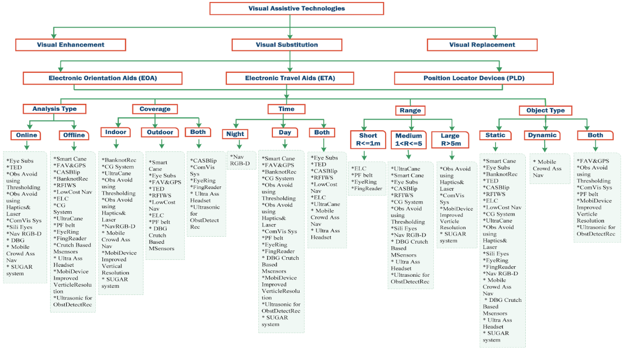
Globally, about 295 million people suffer from some form of moderate to severe vision impairment, ranging from mild distance loss to complete blindness3. To address these challenges, many assistive technologies have been developed. These devices can be categorized as wearable or non-wearable. Wearable technology is embedded in clothes, watches, or accessories, and offers access to information and can be used for various types of signals useful for navigation4. Non-wearable systems (NWS) necessitate an environment to be equipped with sensors to collect data from individuals walking on designated pathways5. These can be divided into image processing (IP) and floor sensors (FP). IP systems employ optic sensors like cameras, scanners and sensors that measure various parameters through digital image processing, whereas FP, are embedded in the floor to capture gait data. Examples of NWS include: navigation sticks, handheld devices and auditory based systems6. These devices typically employ either audio or haptic (vibration-based) feedback, with haptic options having the advantage of preserving auditory attention, with audio feedback often being harder to recognize or can be distracting7,8,9,10. Ultrasonic sensors can be used to detect obstacles in real time. They do this by sending out high, frequency sound waves and then measuring the time it takes for the echo to come back after bouncing off nearby objects11. However, most single element ultrasonic sensors have a limited field of view that is determined by their acoustic beam pattern. They do not provide full hemispherical (180) coverage. The sensor’s sensitivity is highest along the central axis of the beam and gradually lowers toward the edges, which means that the conical detection region is relatively narrow. Therefore, wider lateral spatial awareness in assistive navigation systems is usually possible by the employment of multiple sensors directed in different ways rather than depending on a single wide angle sensor. In the experiment, two ultrasonic sensors were affixed to opposite arms and aimed outward to broaden the lateral awareness of the user’s peripheral blind zones12,13,14. When coupled with vibrating motors for vibrotactile feedback, this approach offers intuitive spatial alerts to users without overwhelming them with sound. A summary of existing devices is shown in Figure 1, which outlines previous research’s organization of current visual assistive technology. In addition to being divided into three primary categories—visual augmentation, substitution, and replacement—devices are further classified according to characteristics that are pertinent to navigation, such as processing type, intended environment, operation time, detection range, and the kinds of objects they can recognize. The image illustrates the variety of methods available for assisting visually impaired individuals by highlighting exemplary examples within each category, and additional information can be found in Index I.
This study proposes a wearable peripheral vision sensor (WPVS) for individuals with peripheral vision loss. The device utilizes ultrasonic sensors and vibrating motors mounted on elastic bands worn on both arms. By orienting the sensors toward the blind spots of the visual field, the device alerts users to nearby obstacles in the upper body level through varying vibration intensities. Compared to other existing devices, this one is easier to use as it does not require being handheld, being strapped on to the arm. The WPVS being on the user’s arms also helps detect objects in areas around the upper body and head level to prevent head injuries. In contrast, existing devices focus on detecting obstacles in the lower body region, such as the feet or legs, to prevent tripping or falling. The goal is to improve spatial awareness, enhance independent mobility, and reduce the risk of upper body collisions in both indoor and outdoor settings.
Methodology
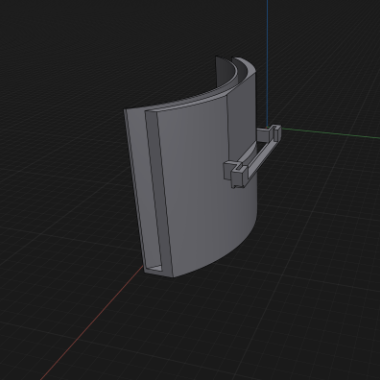
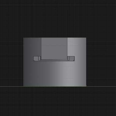
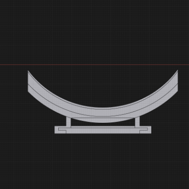
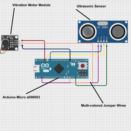
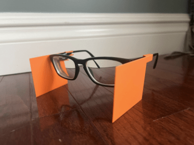
This study utilized a wearable peripheral vision sensor (WPVS) made up of two Arduino Micro boards, compact microcontroller boards used to control electronic components, two HC-SR04 ultrasonic sensors, two small vibrating motors, fourteen dupont wires, two elastic armbands, two small battery packs for power, which will be mentioned as the electronic component, and two 3D-printed components to secure the device, which will be mentioned as the 3D-printed component. The 3D-printed component was designed to attach to the armband and features a slot to hold the ultrasonic sensor, keeping the other parts of the electronic component in place (models shown in Figures 2A–C). The electronic component was wired and programmed (see Index II and Figure 3). The vibration motor activated when an object was detected. Vibration intensity increased as the object moved closer and decreased as it moved farther away. To simulate a loss of peripheral vision for the experiment, another object was 3D-printed to create peripheral blockers attached to glasses (Figure 4), effectively restricting the tester’s peripheral vision.While the peripheral blockers restricted lateral visual input, this simulation does not fully replicate long-term peripheral vision loss. Individuals with actual peripheral visual impairments often develop other strategies to help with their impairment, such as increased head movement and reliance on non-visual cues. Importantly, the WPVS device is designed to complement—not replace—these adaptive behaviors by providing additional real-time spatial information in the user’s blind zones. Therefore, although participants with simulated impairment lacked long-term adaptations, the observed performance improvements demonstrate the device’s potential as an effective supplemental aid. For individuals with genuine peripheral vision loss, who already have compensatory strategies, the device may further enhance situational awareness and safety by reinforcing existing navigation techniques rather than substituting them.
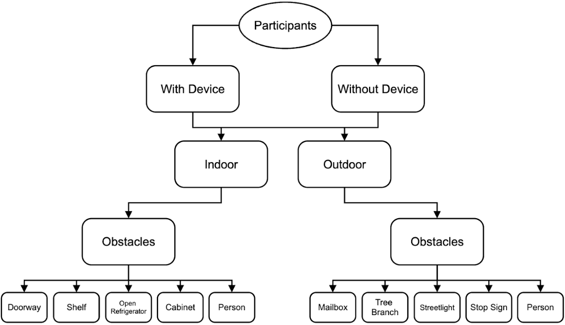
The effectiveness of the WPVS device for individuals with peripheral vision loss was tested through a two-part experiment. The first phase involved initial calibration to determine the maximum detection distance of the electronic component, utilizing three different object sizes: a large wall, a medium cardboard box, and a small metal pole. In the second phase, ten participants of varying heights and ages from 16 to 66 were selected, including one diagnosed with peripheral vision impairment, while the remaining nine wore 3D-printed peripheral blockers to simulate peripheral vision loss. All participants provided informed consent prior to taking part in the study. The participants underwent two trials: one without the WPVS device as a control and then the participants were called back one week later to conduct a trial with the WPVS device attached to elastic armbands on both arms to prevent remembrance of the course. Two courses, indoor and outdoor, were used for the trials, each containing specific obstacles for the participants to navigate. The indoor and outdoor obstacle courses were created to depict the kind of situations people have to deal with in their daily lives. Each course measured about 12 meters, and participants were required to walk at a natural pace from a marked starting point to an end point. There were five obstacles placed along each course, with an average spacing of about 23 meters between them. Indoor obstacles were static objects such as shelves, cabinets, and doorways, whereas outdoor obstacles were items like mailboxes, signs, and tree branches at the upper body level. Before the actual test started, the participants had a short familiarization phase with the WPVS device that lasted about two minutes. During this period, they could experience the vibration feedback while standing still and slowly moving towards a single obstacle. No guided practice on the entire obstacle course was given before data collection in order to reduce learning effects. Reaction times were measured by one researcher with a handheld stopwatch. The researcher stood behind the participant so that he could clearly see the participant’s reactions like stopping, turning, or changing the direction of walking. The researcher knew whether the device was active or not since blinding was not possible due to the visible presence of the device; nevertheless, the same timing procedure was followed in all trials to ensure consistency. Prior to the start of each trial, participants were told to walk through the course at a pace that felt natural to them and to avoid the obstacles as much as possible. They were told that the vibratory signal meant that there was an obstacle nearby; however, since they were not instructed how to react to the vibration, their responses were natural and intuitive. No comments on the performance were given between the trials. This methodology provides sufficient procedural detail for replication, including course dimensions, obstacle configuration, participant instruction, and data collection procedures.
In order to have a direct comparison between the trials and ensure standardized testing conditions, the type of obstacles, their placement, as well as the order, were the same for all participants. Obstacle locations were not changed for different participants or devices, on and device, off conditions. The controlled design used here made sure that differences in performance could be attributed mainly to the use of the WPVS device rather than environmental variability.In order to reduce possible learning effects, the sequence of indoor and outdoor trials was alternated between participants. Obstacles in each course were arranged the same way so that all participants were tested under the same conditions and a direct and fair comparison between trials with and without the device could be made. Although obstacles were not fully randomized, the size of the performance improvement when the WPVS was used even though performance without the device was consistently low indicates that learning or anticipation cannot be the only reasons for the results. The structured design, therefore, helps to determine that the increase in performance was mainly due to the haptic feedback of the device rather than the repeated exposure to the environment. During both trials, researchers recorded the number of obstacles each participant successfully avoided and measured reaction times associated with obstacle detection. Reaction time was defined as the time between the moment an obstacle entered the sensor’s detectable range and the moment the participant exhibited a behavioral response to the vibration (e.g., stopping, turning, or changing trajectory). Timing was performed with a stopwatch manually by a single observer positioned behind the participant to maintain consistency across trials. Although this timing method introduces minor human error, the same procedure and observer were used for all trials to ensure consistency. These reaction times were compared against a baseline reaction time of 0.7 seconds, established by a participant with normal vision and no simulation or WPVS device, ensuring consistent testing conditions and reliable replication of results. Participant demographics are summarized in Table 1.
Figure 5 shows the design of the experiment conducted in the study. Each subject was asked to perform two series of five trials: one in the control condition without the WPVS device and the other in the experimental condition with the device on both arms. Besides, the figure delineates the two testing environmentsindoor and outdoorand illustrates how the measurement of obstacle detection performance was conducted for both conditions. By following such a trial format, each participant was guaranteed to undergo the same testing conditions, thus the differences in their performances with and without the device could be directly compared.
| Participant ID | Peripheral/Normal Vision | Height |
| P1 – control | Normal Vision | 5’10” |
| P2 | Diagnosed Peripheral Loss | 5’9” |
| P3 | Diagnosed Peripheral Loss | 5’5” |
| P4 | Diagnosed Peripheral Loss | 5’6” |
| P5 | Diagnosed Peripheral Loss | 5’8” |
| P6 | Peripheral Vision Loss Simulated by 3d-Printed Blockers | 5’5” |
| P7 | Peripheral Vision Loss Simulated by 3d-Printed Blockers | 5’4” |
| P8 | Peripheral Vision Loss Simulated by 3d-Printed Blockers | 5’7” |
| P9 | Peripheral Vision Loss Simulated by 3d-Printed Blockers | 4’11” |
| P10 | Peripheral Vision Loss Simulated by 3d-Printed Blockers | 6’1” |
| P11 | Peripheral Vision Loss Simulated by 3d-Printed Blockers | 5’11” |
| P12 | Peripheral Vision Loss Simulated by 3d-Printed Blockers | 5’1” |
| P13 | Peripheral Vision Loss Simulated by 3d-Printed Blockers | 5’4” |
Results
The WPVS was evaluated through a series of structured trials, incorporating five distinct indoor obstacles and five outdoor obstacles. These paired trials assessed each participant’s ability to detect and navigate peripheral vision obstacles both with and without the WPVS device. Notably, the WPVSdevice led to a clear improvement in obstacle detection among all individuals with peripheral vision loss, regardless of whether the condition was genuine or simulated.
Prior to the main testing, baseline measurements established the sensor’s maximum effective detection range for different object sizes. The WPVS device reliably detected large surfaces, such as walls, from distances up to 1.8 meters. Detection distances for large, medium, and small objects are summarized in Table 2. Medium-sized objects—like cardboard boxes—were identified at up to 1.5 meters, while smaller items, like poles, were detected at approximately 1 meter (see Table 2). This data provided a foundation for anticipating the WPVS device’s real-world performance across various environments.
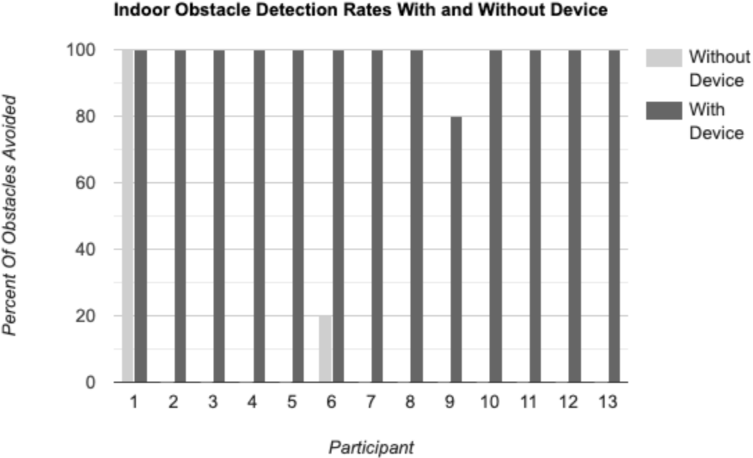
The trials involved ten participants: one with normal vision, one with clinically diagnosed peripheral vision loss, and eight with simulated peripheral vision impairment achieved via 3D-printed blockers attached to their glasses. During indoor trials, participants encountered obstacles such as a doorway, shelf, open refrigerator door, cabinet, and another person. Without the WPVS device, those with restricted vision demonstrated low success rates, averaging just 0.1 obstacles avoided per trial—a mere 2% success rate. Only participant P6 managed to avoid a single obstacle indoors. By contrast, use of the WPVS device resulted in significant improvement: nine out of ten participants successfully avoided all five obstacles, and one participant (P9) missed only a shelf, resulting in a 4 out of 5 success rate. The average indoor success rate rose to 98%. Individual indoor obstacle avoidance outcomes for trials with and without the WPVS device are shown in Tables 3 and 4.
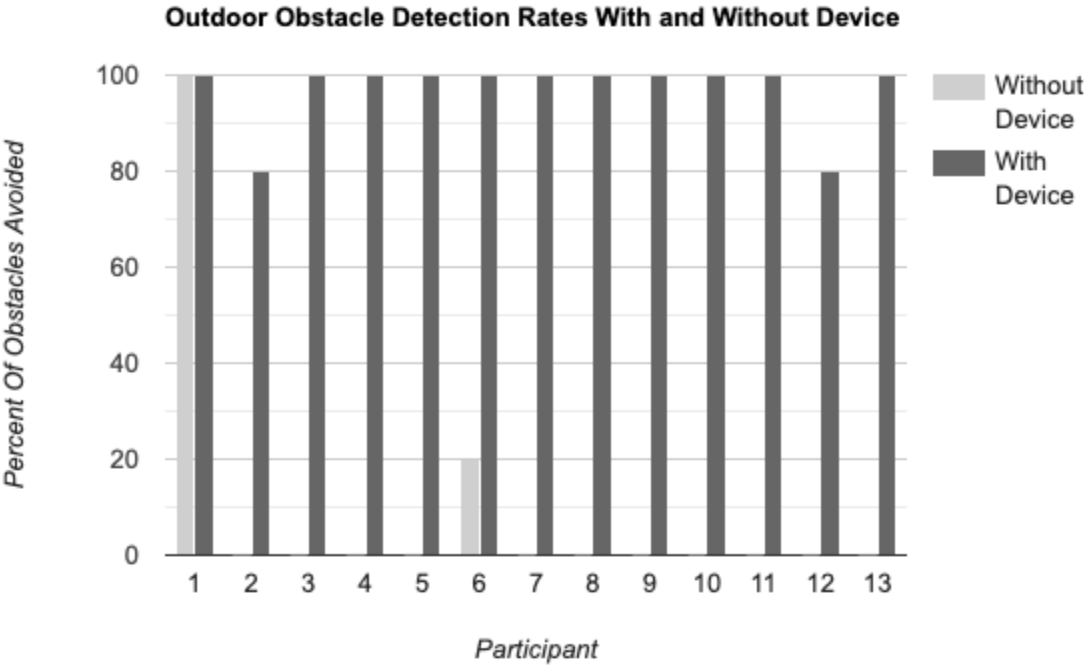
Outdoor trials followed a similar structure, presenting obstacles including a mailbox, tree branch, streetlight, stop sign, and another person. Without the WPVS device, participants’ average obstacle avoidance rate remained at 2%, with only one participant (P6) avoiding any obstacle. With the WPVS, however, seven participants avoided all obstacles, and two missed only the tree branch, leading to an average outdoor success rate of 96%. Particularly noteworthy, the participants with genuine peripheral vision loss (P2, P3, P4, P5) improved from a 0% success rate without the WPVS device to achieving 100% indoors and 80% outdoors, reinforcing the WPVS device’s practical utility (Tables 3/4).
To evaluate the effectiveness of the WPVS device, paired t-tests were used to compare obstacle avoidance performance with and without the device for the same participants. For indoor trials, participants avoided many more obstacles when using the device (mean = 4.89 obstacles) compared to without the device (mean = 0.11 obstacles), t(8) = 32.50, p < 0.001. Similarly, outdoor trials showed a great improvement with the device (mean = 4.78 obstacles) versus without the device (mean = 0.11 obstacles), t(8) = 28.00, p < 0.001. These results indicate that the observed performance gains are statistically significant and unlikely to be due to chance.
Reaction times were also evaluated. Participant-specific reaction times are summarized in Table 5. The control participant (P1) with normal vision exhibited a visual reaction time of 0.7 seconds. Participants using the WPVS device recorded mean vibration reaction times of 0.83 seconds indoors and 0.95 seconds outdoors. While these values were marginally slower than natural visual responses, they remain practical for real-time obstacle avoidance. The fastest WPVS device-assisted reaction time was 0.7 seconds, while the slowest reached 1.2 seconds outdoors—likely due to environmental distractions or variable sensor performance in outdoor conditions (see Table 5).
In summary, the findings indicate that the wearable peripheral vision sensor (WPVS) significantly improves spatial awareness and safety for individuals with compromised peripheral vision. The substantial increase in successful obstacle avoidance, in conjunction with reaction times that closely approximate natural vision, underscores the WPVS device’s promise for practical application in navigation and collision risk reduction.
| Object Size | Detection distance (m) | Notes |
| Large (Wall) | 1.8 | Max Distance |
| Medium (Cardboard Box) | 1.5 | Slightly less distance |
| Small (Pole) | 1 | May have detection issues |
| Participant ID | Condition | Obstacles Encountered | Obstacles Avoided | Success Rate |
| P1 – control | Indoor | 5 | 5 | 100% |
| P2 | Indoor | 5 | 5 | 100% |
| P3 | Indoor | 5 | 5 | 100% |
| P4 | Indoor | 5 | 5 | 100% |
| P5 | Indoor | 5 | 5 | 100% |
| P6 | Indoor | 5 | 5 | 100% |
| P7 | Indoor | 5 | 5 | 100% |
| P8 | Indoor | 5 | 5 | 100% |
| P9 | Indoor | 5 | 4 – shelf | 80% |
| P10 | Indoor | 5 | 5 | 100% |
| P11 | Indoor | 5 | 5 | 100% |
| P12 | Indoor | 5 | 5 | 100% |
| P13 | Indoor | 5 | 5 | 100% |
| P1 – control | Outdoor | 5 | 5 | 100% |
| P2 | Outdoor | 5 | 4 – tree branch | 80% |
| P3 | Outdoor | 5 | 5 | 100% |
| P4 | Outdoor | 5 | 5 | 100% |
| P5 | Outdoor | 5 | 5 | 100% |
| P6 | Outdoor | 5 | 5 | 100% |
| P7 | Outdoor | 5 | 5 | 100% |
| P8 | Outdoor | 5 | 5 | 100% |
| P9 | Outdoor | 5 | 5 | 100% |
| P10 | Outdoor | 5 | 5 | 100% |
| P11 | Outdoor | 5 | 5 | 100% |
| P12 | Outdoor | 5 | 4 – tree branch | 80% |
| P13 | Outdoor | 5 | 5 | 100% |
| Participant ID | Condition | Obstacles Encountered | Obstacles Avoided | Success Rate |
| P1 – control | Indoor | 5 | 5 | 100% |
| P2 | Indoor | 5 | 0 | 0% |
| P3 | Indoor | 5 | 0 | 0% |
| P4 | Indoor | 5 | 0 | 0% |
| P5 | Indoor | 5 | 0 | 0% |
| P6 | Indoor | 5 | 1 | 20% |
| P7 | Indoor | 5 | 0 | 0% |
| P8 | Indoor | 5 | 0 | 0% |
| P9 | Indoor | 5 | 0 | 0% |
| P10 | Indoor | 5 | 0 | 0% |
| P11 | Indoor | 5 | 0 | 0% |
| P12 | Indoor | 5 | 0 | 0% |
| P13 | Indoor | 5 | 0 | 0% |
| P1 | Outdoor | 5 | 5 | 100% |
| P2 | Outdoor | 5 | 0 | 0% |
| P3 | Outdoor | 5 | 0 | 0% |
| P4 | Outdoor | 5 | 0 | 0% |
| P5 | Outdoor | 5 | 0 | 0% |
| P6 | Outdoor | 5 | 1 | 20% |
| P7 | Outdoor | 5 | 0 | 0% |
| P8 | Outdoor | 5 | 0 | 0% |
| P9 | Outdoor | 5 | 0 | 0% |
| P10 | Outdoor | 5 | 0 | 0% |
| P11 | Outdoor | 5 | 0 | 0% |
| P12 | Outdoor | 5 | 0 | 0% |
| P13 | Outdoor | 5 | 0 | 0% |
| Participant ID | Condition | Reaction Time (sec) | Normal Vision Reaction Time (sec) | Difference (sec) | Percent Change |
| P1 – control | Indoor | 0.7 | 0.7 | +0.0 | 0% |
| P2 | Indoor | 0.8 | 0.7 | +0.1 | 14% |
| P3 | Indoor | 0.8 | 0.7 | +0.1 | 14% |
| P4 | Indoor | 0.8 | 0.7 | +0.1 | 14% |
| P5 | Indoor | 0.8 | 0.7 | +0.1 | 14% |
| P6 | Indoor | 0.8 | 0.7 | +0.1 | 14% |
| P7 | Indoor | 0.9 | 0.7 | +0.2 | 28% |
| P8 | Indoor | 0.8 | 0.7 | +0.1 | 14% |
| P9 | Indoor | 0.9 | 0.7 | +0.2 | 28% |
| P10 | Indoor | 0.9 | 0.7 | +0.2 | 28% |
| P11 | Indoor | 1.0 | 0.7 | +0.3 | 43% |
| P12 | Indoor | 0.8 | 0.7 | +0.1 | 14% |
| P13 | Indoor | 0.8 | 0.7 | +0.1 | 14% |
| P1 | Outdoor | 0.9 | 0.7 | +0.2 | 28% |
| P2 | Outdoor | 0.9 | 0.7 | +0.2 | 28% |
| P3 | Outdoor | 0.9 | 0.7 | +0.2 | 28% |
| P4 | Outdoor | 0.9 | 0.7 | +0.2 | 28% |
| P5 | Outdoor | 0.9 | 0.7 | +0.2 | 28% |
| P6 | Outdoor | 1.0 | 0.7 | +0.3 | 43% |
| P7 | Outdoor | 0.9 | 0.7 | +0.2 | 28% |
| P8 | Outdoor | 1.1 | 0.7 | +0.5 | 71% |
| P9 | Outdoor | 0.9 | 0.7 | +0.2 | 28% |
| P10 | Outdoor | 0.8 | 0.7 | +0.1 | 14% |
| P11 | Outdoor | 1.2 | 0.7 | +0.5 | 71% |
| P12 | Outdoor | 1.0 | 0.7 | +0.3 | 43% |
| P13 | Outdoor | 1.0 | 0.7 | +0.3 | 43% |
Discussion
This research indicates that the wearable peripheral vision sensor (WPVS) device significantly improved obstacle awareness and navigation for individuals experiencing peripheral vision loss. Participants with limited peripheral vision, whether due to natural conditions or simulated scenarios, demonstrated a marked enhancement in their ability to avoid obstacles while using the WPVS device, especially in controlled indoor settings. The success rate increased from 2% without the WPVS device to 98% with it. This improvement supports the effectiveness of the ultrasonic sensor and vibration motor system. Together, they convert environmental data into practical tactile feedback. These results validate the initial hypothesis that a cost-effective, compact WPVS device employing ultrasonic sensors and haptic feedback can effectively assist individuals with visual field impairments. Compared to the existing assistive technologies like smart canes, infrared belts, and neck, or chest, mounted ultrasonic devices, the WPVS device has several main benefits. First, smart canes mainly detect obstacles on the ground and only work when the user is actively using the cane. Also, they hardly detect any hazards at the upper body level. Secondly, infrared belts and torso mounted systems offer a wider range of coverage but might feel less natural because of centralized feedback, and they are also more expensive. However, the WPVS device isolates the lateral blind zones of the upper body by using the arm mounted sensors, whereby it allows for the natural spatial mapping through the bilateral haptic feedback. Moreover, the WPVS device is cheap, light, and hardly requires any training, which makes it a viable option for users who want to stay aware of their peripheral obstacles. Importantly, even those who had never used the WPVS device before were able to operate it successfully after a brief introduction, suggesting an intuitive design that requires minimal training. Furthermore, baseline range testing established performance expectations for the WPVS device: it could identify large surfaces up to 1.8 meters away, medium obstacles at 1.5 meters, and smaller items at approximately 1 meter. This detection range likely played a crucial role in the high success rate, particularly indoors where objects generally fell within these distances. Nonetheless, the experiment also identified certain limitations. In one case, a participant was unable to detect a shelf indoors, indicating that the WPVS device’s effectiveness might be influenced by the angle of approach or the shape and reflectivity of the object. Outdoor trials were not comprehensively analyzed in this study. However, preliminary observations suggest that external factors may affect performance. These factors include background noise, lighting variation, and uneven walking surfaces. These elements merit further exploration in subsequent studies.
The project still showcases several notable advantages to the development of assistive peripheral vision WPVS devices. The WPVS device is affordable, lightweight, and can be comfortably worn on the arm, making it a viable option for those who lack access to pricier assistive technologies. Its straightforward design also allows for scalability and customization for future improvements. For instance, upcoming versions could integrate additional sensors for broader detection capabilities, implement directional vibration patterns, or enable users to modify sensitivity settings according to their surroundings. Compared to other devices, such as a smart stick or cane, this peripheral device helps detect objects in areas where it matters most, around the upper body and head, compared to one’s feet and legs. Most other devices also require something to be held in the user’s hand, while this WPVS device just needs to be worn on the arm without requiring manual handling to keep it on. These features suggest promising applicability in real-world settings for use in urban environments, such as navigating crowded city sidewalks, crossing streets, or using public transportation, where situational awareness is critical and peripheral obstacles are frequent. With this being said, this device also has some limiting factors, such as not being able to detect all objects in the user’s body’s vertical area. This could be solved with the integration of more sensors on the device. Another slight issue would be the size of the battery powering the electronic component which is of a large size. This can be solved by finding or creating a smaller power source that fits better with the minimal WPVS device.
In summary, this WPVS device demonstrates significant promise as an assistive tool for individuals experiencing peripheral vision loss, particularly in familiar settings like homes or indoor public areas. With additional refinement and testing, it has the potential to become an essential resource for enhancing independence and safety during daily navigation.
Conclusion
My review of temporal blindness (peripheral blindness), suggests challenges in the navigation system for the visually impaired with multiple wearable and nonwearable systems
This research effectively showed that a wearable system, ultrasonic sensors used for obstacle detection can significantly enhance navigation and spatial awareness for individuals with peripheral vision loss. The WPVS device, made up of ultrasonic sensors and vibrating motors attached to armbands, delivered haptic feedback that notified users of nearby obstacles in their blind spots. In controlled indoor and outdoor experiments, users of the WPVS device displayed a significant enhancement in obstacle navigation—raising the average success rate greatly when using it. Reaction times when operating the WPVS device were similar to those of people with normal vision, confirming the system’s real-time responsiveness and usability. Even those unacquainted with the WPVS device adjusted swiftly, highlighting its user-friendly design. In contrast to current technologies like smart canes, infrared belts, and audio systems, this armband presents an easy-to-use option that does not interfere with hearing or demand extensive training. Although it has drawbacks—like restricted detection angles and range, as well as non-directional feedback—it still serves as a scalable basis for future improvements. Through improvements such as multi-angle sensors, directional feedback, and sensitivity that adapts to the environment, this technology has the potential to be a vital mobility aid for individuals with visual impairments. In conclusion, the WPVS device addresses a vital requirement for accessible, efficient, and wearable assistive technology, enabling increased independence and safety for individuals impacted by peripheral vision loss. Future research should investigate long-term usability in real-world public environments, such as crowded cities and public transport systems, and explore integrating this technology into existing mobility tools. Collaborations with vision rehabilitation specialists and end-users could also guide the development of personalized feedback systems for broader adoption.
Index I – Large Literature Review
A wide array of assistive technologies have been developed to aid individuals with visual impairments, particularly for navigation and obstacle detection. These devices typically fall into three categories: camera-based systems, sensor-integrated canes, and wearable haptic tools. Each of these approaches offers unique benefits and limitations depending on the user’s needs and the target environment.
Camera-based systems, such as the OrCam and CAPture, utilize optical input and artificial intelligence to recognize text, faces, and objects. These devices provide rich environmental information and are often head-mounted or worn as glasses16,17. However, they rely heavily on lighting conditions and require users to interpret audio feedback, which may overwhelm or distract from other essential auditory cues in the environment.
Sensor-enhanced canes, such as the Smart Cane, integrate ultrasonic sensors, GPS tracking, and even bus schedule detection into traditional cane designs. These tools improve upon standard white canes by identifying objects through voice alert and vibrations18. Dual-sensor systems that combine foot-level sensors with shoe-based inputs extend obstacle detection to the lower extremities19,14. While effective for detecting ground-level and knee-height obstacles, these systems still require the user to hold the cane, limiting upper-body or head-level object awareness.
In contrast, wearable devices such as the BuzzClip, iSonar, Miniguide, and Ultracane offer haptic or audio feedback without needing manual operation. Many of these tools are clipped to clothing or worn around the neck or abdomen20,21,22. For instance, the iSonar delivers vibrational alerts through skin contact on the chest, while the Ultracane includes dual ultrasonic sensors to detect obstacles at both leg and torso height. These devices are often preferred for their “free-ears” design, which preserves auditory awareness—an essential input for visually impaired users. Additionally, designs such as SonarGlasses and the infrared sensor belt attempt to integrate detection into accessories like glasses or belts, offering varying degrees of portability and directional awareness21,23,24.
Despite these innovations, most existing systems either target the lower body or rely on handheld or neck-mounted configurations. Few designs focus specifically on peripheral vision loss—such as temporal hemianopia—or provide targeted feedback to lateral blind zones. Moreover, many current solutions are costly or cumbersome, limiting accessibility and daily use for individuals seeking lightweight, affordable alternatives. These gaps in the current landscape underscore the need for simple, wearable, arm-mounted systems like the one proposed in this study, which aim to provide real-time feedback in a user’s temporal visual field while maintaining comfort, affordability, and ease of use25.
Index II – Code
// Define the pins for the ultrasonic sensor and vibrating motor
const int trigPin = 8;   // Trigger pin for ultrasonic sensor
const int echoPin = 9;   // Echo pin for ultrasonic sensor
const int motorPin = 10; // Motor pin (PWM) connected to the vibrating motor

long duration;
int distance;
int motorSpeed; // Variable to control the intensity of the motor's vibration

unsigned long timestamp;  // Variable to store the timestamp (milliseconds)

void setup() {
 // Start the serial communication for debugging
 Serial.begin(9600);

 // Set up the ultrasonic sensor pins
 pinMode(trigPin, OUTPUT);
 pinMode(echoPin, INPUT);

 // Set the motor pin as output for PWM control
 pinMode(motorPin, OUTPUT);
}

void loop() {
 // Get the current timestamp (milliseconds since the Arduino started)
 timestamp = millis();

 // Trigger the ultrasonic sensor to emit a pulse
 digitalWrite(trigPin, LOW);
 delayMicroseconds(2);
 digitalWrite(trigPin, HIGH);
 delayMicroseconds(10);
 digitalWrite(trigPin, LOW);

 // Read the time it took for the pulse to return
 duration = pulseIn(echoPin, HIGH);

 // Calculate the distance in centimeters
 distance = duration * 0.0344 / 2;

 // Print the timestamp and distance to the serial monitor (for testing)
 Serial.print("Timestamp: ");
 Serial.print(timestamp);
 Serial.print(" ms, ");
 Serial.print("Distance: ");
 Serial.print(distance);
 Serial.println(" cm");

 // Map the distance to a motor speed (PWM value)
 if (distance < 10) {
   motorSpeed = 255; // Maximum vibration intensity
 } else if (distance > 300) {
   motorSpeed = 0; // No vibration if object is too far
 } else {
   // Map the distance to a motor speed between 0 and 255
   motorSpeed = map(distance, 10, 300, 255, 0);
 }

 // Control the motor intensity with PWM (vibration)
 analogWrite(motorPin, motorSpeed);

 delay(100); // Delay between readings
}
References
- H. Strasburger, I. Rentschler, M. Jüttner. Peripheral vision and pattern recognition: a review, Journal of Vision. 11, 13 (2011). [↩]
- G. Kbar et al. Utilizing sensor networks to develop a smart and context-aware solution for people with disabilities at the workplace, International Journal of Distributed Sensor Networks. 12, 1550147716658606 (2016). [↩]
- GBD 2019 Blindness and Vision Impairment Collaborators, & Vision Loss Expert Group of the Global Burden of Disease Study. Trends in prevalence of blindness and distance and near vision impairment over 30 years: an analysis for the Global Burden of Disease Study. Lancet Glob Health. 9, 133 (2019). [↩]
- R. M. Al-Eidan, H. Al-Khalifa, A. M. Al-Salman. A review of wrist-worn wearables: sensors, models, and challenges, Journal of Sensors. 2018, 5853917 (2018). [↩]
- A. Muro-de-la-Herran, B. Garcia-Zapirain, A. Mendez-Zorrilla. Gait analysis methods: an overview of wearable and non-wearable systems, highlighting clinical applications, Sensors. 14, 2 (2014). [↩]
- M. H. Abidi, A. N. Siddiquee, H. Alkhalefah, V. Srivastava. A comprehensive review of navigation systems for visually impaired individuals, Heliyon. 10, 11 (2024). [↩]
- W. Elmannai, K. Elleithy. Sensor-Based Assistive Devices for Visually-Impaired People: Current Status, Challenges, and Future Directions, Sensors. 17, 2 (2017). [↩]
- M. D. Messaoudi, B. J. Menelas, H. Mcheick. Review of Navigation Assistive Tools and Technologies for the Visually Impaired, Sensors. 22, 9 (2022). [↩]
- Y. Al-Handarish et al. A survey of tactile-sensing systems and their applications in biomedical engineering, Advances in Materials Science and Engineering. 2020, 4047937 (2020). [↩]
- E. Casanova, D. Guffanti, L. Hidalgo. Technological advancements in human navigation for the visually impaired: a systematic review, Sensors. 25, 2213 (2025). [↩]
- S. Vítek, M. Klima, L. Husnik, D. Spirk. New possibilities for blind people navigation, 2011 International Conference on Applied Electronics (AE). 1–4 (2011). [↩]
- W. Elmannai, K. Elleithy. Sensor-Based Assistive Devices for Visually-Impaired People: Current Status, Challenges, and Future Directions, Sensors. 17, 5 (2017). [↩]
- F. G. H. Fathauher. Ultrasonic sensor, IEEE Transactions on Ultrasonics. 3, 57 (1999). [↩]
- D. P. M. Donald. Optimizing sensor selection: choosing an ultrasonic sensor for proximity or distance measurement, IEEE Transactions on Ultrasonics. 3, 23–36 (2000). [↩] [↩]
- W. Elmannai, K. Elleithy. Sensor-Based Assistive Devices for Visually-Impaired People: Current Status, Challenges, and Future Directions, Sensors. 17, 3 (2017). [↩]
- D. Dakopoulos, N. G. Bourbakis. Wearable Obstacle Avoidance Electronic Travel Aids for Blind: A Survey, 2016 IEEE International Conference on Recent Trends in Electronics, Information & Communication Technology (RTEICT). 40, 26 (2010). [↩]
- N. Bhati, V. C. Samsani, R. Khareta, T. Vashisth, S. Sharma, V. Sugumaran. CAPture: A Vision Assistive Cap for People with Visual Impairment, 2021 8th International Conference on Signal Processing and Integrated Networks (SPIN). 1 (2021). [↩]
- M. H. A. Wahab, A. A. Talib, H. A. Kadir, A. Johari, A. Noraziah, R. M. Sidek, A. A. Mutalib. Smart Cane: Assistive Cane for Visually-impaired People, IJCSI International Journal of Computer Science Issues. 8, 21 (2011). [↩]
- S. T. Alam, S. Shrivastava, S. T. Alam. Smart Assistive Device for Visually Impaired People, International Journal of Engineering Research & Technology (IJERT). 4, 962 (2015). [↩]
- W. Elmannai, K. Elleithy. Sensor-Based Assistive Devices for Visually-Impaired People: Current Status, Challenges, and Future Directions, Sensors. 17, 14 (2017). [↩]
- S. Vorapatratorn, K. Nambunmee. iSonar: an obstacle warning device for the totally blind, Journal of Assistive, Rehabilitative & Therapeutic Technologies. 2, 1 (2014). [↩] [↩]
- A. Rodríguez, J. J. Yebes, P. F. Alcantarilla, L. M. Bergasa, J. Almazán, A. Cela. Assisting the visually impaired: obstacle detection and warning system by acoustic feedback, Sensors. 12, 17476–17496 (2012). [↩]
- R. K. Katzschmann, B. Araki, D. Rus. Safe Local Navigation for Visually Impaired Users With a Time-of-Flight and Haptic Feedback Device, IEEE Transactions on Neural Systems and Rehabilitation Engineering. 26, 583 (2018). [↩]
- H.-C. Wang, R. K. Katzschmann, S. Teng, B. Araki, L. Giarré, D. Rus. Enabling independent navigation for visually impaired people through a wearable vision-based feedback system, 2017 IEEE International Conference on Robotics and Automation (ICRA). 6533–6540 (2017). [↩]
- SonarGlasses. Sonarglasses ultrasonic navigation glasses. https://sonarguide.com/sonar-glasses/ (2022). [↩]


