
Abstract
Introduction: Current supersonic and hypersonic vehicles lack a method of freely transitioning between conventional, ramjet and scramjet operation. A new type of engine, the free-jet combustor (FJC), can transition between ramjet and scramjet operation without altering its geometry. A novel engine assembly with variable-geometry inlets integrates a conventional engine with the FJC and controls the mode transition between conventional and ramjet propulsion. The purpose of this study was to optimize the design of an FJC that would be mounted within this novel engine assembly.
Methods: Analytical equations were used to broadly examine the optimal inlet radius and area ratio for the FJC (in scramjet mode), as well as the effect altitude had on FJC thrust.
Results: An area ratio of 0.15 was found to be optimal for the FJC’s operation. An inlet radius of 0.35 m was chosen to provide acceptable thrust for the FJC throughout its entire operating regime. The FJC greatly declines in thrust as altitude increases and produces <500 N of thrust at 70 km for all operable Machs. A maximum operating altitude of 60 km was determined to be optimal for the FJC.
Conclusions: This study identified several key trends of FJC performance and produced a fully-dimensioned diagram of the FJC from the resulting data. This paper also put forth the larger engine assembly, which, if validated, will allow aircraft to consistently travel from a standstill to Mach 8+.
Keywords: Free-jet combustor, ramjet, scramjet, aircraft propulsion, engine assembly, supersonic flight, hypersonic flight, variable-geometry inlets, mode transition
1. Introduction
Ramjet and scramjet (RS) engines have allowed aircraft to break the speed limits of turbojet/turbofan propulsion (~Mach 4) and enter into the hypersonic (>Mach 5) flight regime1. At these speeds, RS engines perform with greater efficiency than any other method of atmospheric propulsion, and are thus utilized more frequently for high-speed applications1. RS engines serve as an important middle ground in propulsion technology which bridges the gap between commercial aircraft propulsion and rocket engines. Improvements in RS engine performance would not only benefit commercial air travel, long-haul cargo transport, or military applications, but would also increase access to space and/or high-altitude scientific opportunities2. Trefny et al. recently devised an RS engine concept, the free-jet combustor (FJC), which can switch modes between a ramjet and a scramjet to achieve thrust at Machs from 4 to 8+3. However, RS engines cannot effectively function below Mach 4. A unique engine assembly involving variable inlet geometry created by Sanders et al. can alleviate this issue by integrating the FJC with a conventional turbojet engine4,5. This study seeks to optimize one section of the assembly—the FJC itself—for a wide range of operating Machs and altitudes through an analytic examination, thus laying the groundwork for future studies on this assembly including full CFD simulation and wind-tunnel validation.
1.1 Ramjet and Scramjet Engines
Both ramjets and scramjet engines are characterized by a lack of moving parts6. As opposed to a turbojet/turbofan engine, which compresses incoming air by means of a rotating compressor, RS engines compress external air by using the aircraft’s speed to “ram” the air into the engine6. The difference between ramjets and scramjets lies in the speed of the combusted air: ramjet engines slow incoming air to subsonic speeds for the combustion process, while scramjet engines conduct combustion in supersonic air6. Trefny et al. stress that scramjets are the ideal engine for high-Mach applications because their supersonic combustion process produces very large amounts of thrust3. However, due to the large speed requirement of scramjets, ramjets are necessary for efficient propulsion at speeds below Mach 57,6.
1.2 Issues with Traversing the Flight Range
Despite the potential for aircraft to travel faster than ever before with the utilization of RS engines, the specialized nature of both ramjets and scramjets brings with it several drawbacks. Two major problems limit current RS engine design from broader aerospace applications. First, due to large variations in airflow factors across the RS flight regime (Machs 4-5+), neither ramjets nor scramjets are capable of operating throughout the entire speed range. While this problem may be disregarded for aircraft which do not plan on traveling past Mach 5 (which may simply utilize ramjets), it is of great concern to very high-speed applications, such as potential spaceplanes. Thus, an engine design must be found that can traverse the Mach range without losing efficiency.
Second, RS engines lack power at speeds below Mach 4. This is the lower bound at which air compression via the aircraft’s own speed becomes viable. Constructed RS testbed aircraft, such as NASA’s X-43 or Boeing’s X-51, have utilized a carrier aircraft and discardable rocket boosters to accelerate to Mach 48,9. However, there is not yet a reusable method of accelerating an RS engine to this desired operating range. Thus, an engine design must be found that can bring the aircraft to Mach 4 to allow for the activation of the RS engine.
1.3 The Free-Jet Combustor
A new engine type named the free-jet combustor (FJC) was devised and simulated by Trefny et al.3. The engine is designed as a ramjet which may operate in a scramjet mode once airflow conditions have passed the transition point (around Mach 5-6)7,10. In ramjet mode, supersonic air enters through the inlet and slows down to subsonic speeds as it expands to fill the combustion chamber3. Once the Mach transition point is passed, flow separation occurs at the inlet, and the airflow disconnects from the combustion chamber walls3. In this state, known as “free-jet” or scramjet mode, supersonic air does not contact the combustion chamber walls in any way, but instead flows directly from the inlet to the nozzle throat3. Trefny et al. explain that the FJC provides several benefits compared to other mode-switching designs3. Preventing airflow contact with the chamber walls reduces the engine heat load significantly3. Shocks within the free-jet stream increase rates of fuel mixing and combustion3. Most importantly, however, there is no requirement for variable geometry to accommodate both ramjet and scramjet modes, since the engine is built like a ramjet, and natural airflow structures act as the desired scramjet geometry3. Fundamentally, the FJC makes RS engine operation over the Mach flight regime possible with a simple and effective design. However, for the FJC to function at optimal conditions, it must integrate with a larger engine assembly that includes special external geometry.
1.4 Variable Inlet Geometry
Because the FJC will not be able to move the plane from a standstill, a “conventional” jet engine (turbojet, turbofan, or a variable-cycle engine) must be used at some point. Foster et al. have developed and built a variable-geometry inlet which can supply air to two engines in varying ratios11. A turbine engine is mounted above a dual-mode scramjet engine (for this paper, the FJC)11. The two engines share a nozzle and inlet to reduce weight compared to a separated two-engine design11. Also included is a variable-geometry surface which changes configuration based on aircraft speed in order to reduce the interference of airflow shocks on the inlet4,5. From takeoff to RS operational speeds (Mach 4), incoming air is directed fully to the turbine engine11. However, as soon as Mach 4 is reached, the inlet allows some air to reach the FJC in order to spool up the engine11. Once the FJC is fully operational, the inlet will close off air to the turbine and direct all of it to the FJC11. As the vehicle accelerates further, the turbine engine will spool down Tunnel11. Returning from hypersonic to low speeds presumably follows this process in reverse. Foster et al. have demonstrated the feasibility of their concept by building a scale prototype and operating it in the NASA 10 x 10 ft SuperSonic Wind Tunnel11. Although weight is of concern when mounting two engines, this concept nonetheless provides a simple way to integrate a conventional jet engine with the FJC11. This paper will focus solely on the FJC, leaving the quantitative examination of this variable inlet scheme for a future study.
1.5 FJC Optimization
The purpose of this study was to optimize an FJC that is meant to be integrated with the variable inlet. The final FJC design can bring an aircraft from ~Mach 4 to Mach 8 and beyond, with material and thermodynamic stresses imposing the only conceivable speed limit. We designed this FJC as a small prototype for use in an autonomous test vehicle. We hope to build upon this FJC concept to facilitate the operation of commercial hypersonic aircraft at altitudes ranging from 20-60 km (12-37 mi) above sea level. We also hope to pave the way for single stage or double stage to orbit launch vehicles by greatly expanding the non-rocket engine flight regime. We constructed a two-dimensional cutaway of the final engine assembly in order to demonstrate the geometry of the design.
2.1 Materials and Methods
2.1 Overall Methodology
The methodology of this study is twofold. First, using the analytical equations devised by Riggins et al. and data visualization capabilities provided by MATLAB®, trends in FJC performance were determined12. These trends dictated key dimensions for the FJC’s geometry. Second, via qualitative investigation of the variable-geometry inlet system, a general proposal for the design uniting the FJC with the variable-geometry assembly was devised4,5.
2.1 Tools Used
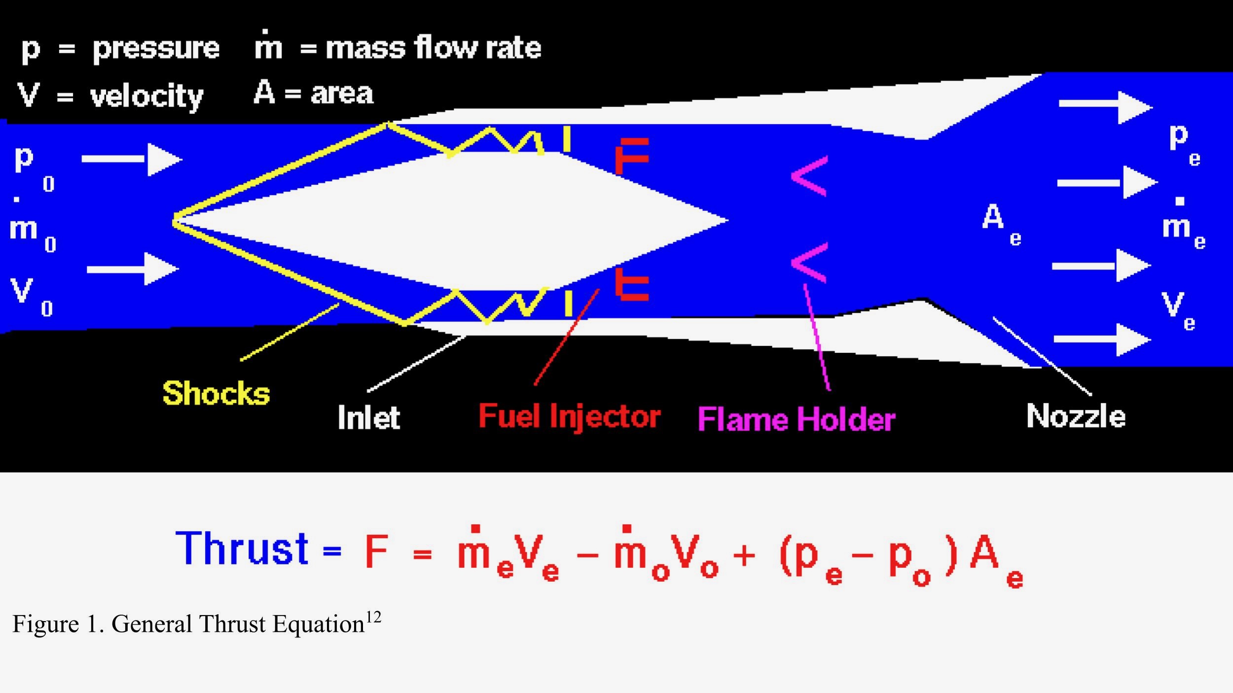
The majority of the displayed data was derived using analytical equations from Riggins et al.’s work12. Additional equations simulating altitudinal changes in atmospheric pressure and temperature, as well as the engine’s thrust, were provided by NASA13. MATLAB® version 24.1 (release R2024a) was used for computation and the graphical presentation of the data. AutoCAD® was utilized to draft and annotate diagrams of the FJC and the larger engine assembly. This section will discuss Riggins et al.’s equations and examine the factors that influence FJC performance. Below are the three NASA equations modeling altitudinal change in air temperature, pressure, and density, respectively13. In addition, Figure 1 details the general thrust equation that was utilized for this study14.
(1) 
(2) 
(3) 
Where for all equations, T is the temperature in degrees Celsius, h is the height in meters above sea level, p is the static pressure in kPa, and ρ is the density in kg/m3.
2.3 Exit Mach Equation
There are four factors present in the aforementioned thrust equation: pressure, mass flow rate, velocity, and area. While we can easily determine almost all of them from the environment and known design factors (e.g. mass flow rate from air density, inlet velocity, and cross-sectional entrance area), the exit velocity (Ve) must be solved for. To that end, Riggins et al. have derived the following equation12:
(4) 
Me is the Mach speed (i.e. exit velocity) of the air at the engine exit and is the value that must be solved for. To streamline solving the equation, certain numerical assumptions were made. Pti/Pte, the last term of the equation, is known as the total pressure recovery (the ratio of engine inlet pressure to nozzle exit pressure). The engine inlet pressure was derived using the empirical MIL-Spec inlet pressure recovery model15. The nozzle exit pressure was assumed to equal the freestream air pressure. With all other variables except Me substituted for corresponding values, the resulting equation is quintic in terms of Me, and we considered which output value would be most appropriate to use.
2.4 Assumptions
Several assumptions were made to streamline the mathematical calculations and procurement of data. We assumed that injected fuel achieved complete combustion before reaching the nozzle exit (Trefny et al.’s work supported this assumption well)3. All gasses present were assumed to be ideal and their thermodynamic properties unchanged throughout the engine12. Furthermore, stations of interest (the inlet plane and the nozzle exit plane) were assumed to have uniform airflow12. For the solutions of Equation 1, the second output was always used. With any given input parameters, three of the five Me values were complex, and one was unrealistically small (Me of ~.0001-.03). The second Me value fell into a more realistic range of Mach output speeds, so it was used for calculations. Finally, perfect expansion of the exit gases was assumed. This assumption could be realistically supported by variable nozzle technology, which is already in use on modern military jets. However, perfect expansion at every altitude is impossible. Given this fact, as well as all of our other assumptions, we expect that real-world or CFD testing of the FJC will yield lower thrust than what we calculate in the Results section. This paper presents the “ideal” numbers in order to examine relevant trends in the FJC’s performance, not to predict FJC thrust with absolute certainty.
3. Results
3.1 Overview
For the purpose of FJC optimization, this paper mainly focuses on aspects of the inlet/engine design directly related to its geometry. Other factors, such as the type of fuel used and the fuel-air ratio of the engine, are not necessarily tied to the geometry and may be determined by hardware such as fuel injectors and piping, so we did not study these aspects of the FJC. For the purposes of this paper, the FJC utilizes ethylene fuel; Svensson found ethylene powerful due to its low ignition time, and Trefny et al. confirmed ethylene’s viability across the FJC’s entire Mach regime (Machs ~4-8+)7,16. We also selected a fuel-air ratio of 0.02 in accordance with NASA’s parameters for scramjet engine design14. This number is not intended to imply that the FJC will have a fixed fuel-air ratio; hypersonic engines typically require variable fuel intake to maintain thrust and optimal combustion throughout their flight regime17. Rather, this baseline fuel-air ratio was used to study the general trends of the FJC’s performance without the need to produce a complex fuel injection strategy (which would fall outside the paper’s focus). We aimed for the FJC to cruise at 60,000 meters altitude at Mach 8. We chose an altitude of 60 km above sea level to examine the FJC’s performance at an altitude near the theoretical height limit of scramjet performance. We selected a cruising speed of Mach 8 as a “midpoint” speed between the FJC’s minimum scramjet speed (~Mach 6.0-6.5) and a reasonable maximum for this study (~Mach 10)3. Do note that the FJC can operate past Mach 10 without issue and can operate as low as Mach 4 in ramjet mode. Finally, we tested the FJC with an inlet radius of 0.35 m (providing ~0.38 m2 of cross-sectional entrance area) in accordance with the goal laid out in the Introduction section: making a small prototype engine.
3.2 Study of Area Ratio
The primary design element of consideration was the ratio between the area of the engine inlet (or intake) and the area of the nozzle exit. Area ratio is ultimately the largest factor affecting the engine and inlet’s geometry.
Figures 2a-c display, in three dimensions, the effect that area ratio has on engine thrust at Mach speeds ranging from 3.25 to 10.
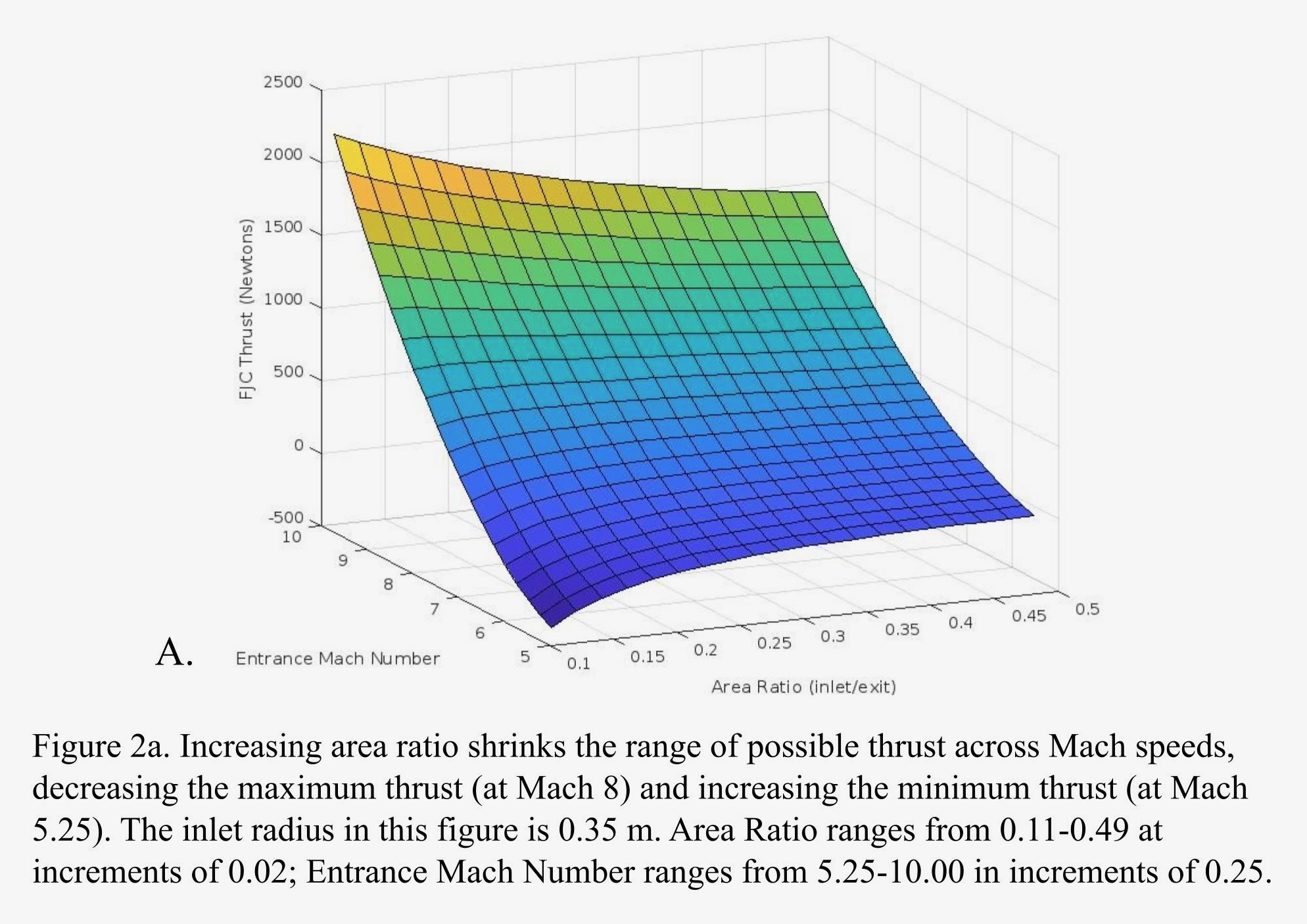

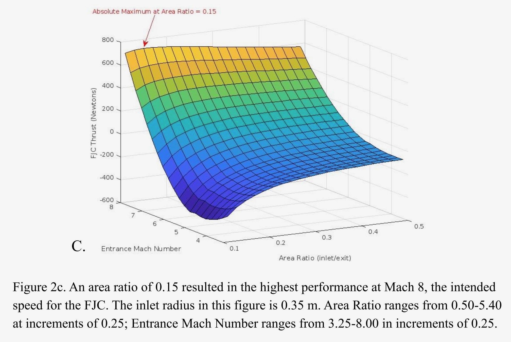
Figure 2 paints a clear picture of general engine performance across the FJC flight regime. Increasing Mach number concomitantly increases thrust. Below ~Mach 6.5, the FJC ceases to produce net positive thrust. Decreasing area ratio increases the thrust produced at the highest Mach number while decreasing the thrust produced at the lowest Mach number (essentially widening the range of possible thrust values). Increasing area ratio results in the opposite effect (shrinking the range of possible thrust values). Figures 2a and 2b demonstrate that the FJC will function at Mach numbers above its intended cruising speed of Mach 8. Figure 2c demonstrates that the FJC ceases to produce net positive thrust below ~Mach 6.5. This behavior corresponds with Trefny et al.’s findings, which state that the free-jet combustion mode will fail if the FJC slows to Mach 6 or below3. The small “notch” on Figure 2b indicates where the MIL-Spec recovery model switches from its supersonic to its hypersonic equation, causing a slight discontinuity in thrust values. At the FJC’s intended cruising speed, Mach 8, an area ratio of 0.15 provides 722.659 N of thrust—the absolute maximum value for that Mach. We therefore selected this area ratio for the FJC design. Note that this area ratio produces less thrust at lower Machs than a larger area ratio. However, we still settled on this area ratio because it results in a non-linear thrust gain when operating faster than cruising speed. For example, at Mach 10, an area ratio of 0.15 provides 2046.62 N of thrust—nearly a three-fold increase in thrust for a 25% increase in Mach number. Table 1 compares these values with the thrust produced at Machs 8 and 10 using area ratios of 0.25 and 0.35, respectively.
| Area Ratio | 0.15 | 0.25 | 0.35 |
| Mach | – | – | – |
| 8 | 722.659 N | 690.683 N | 639.488 N |
| 10 | 2046.62 N | 1789.25 N | 1612.23 N |
| – | – | – | – |
| Percentage increase from Mach 8 to Mach 10 | 183.207 % | 159.055 % | 152.112 % |
3.3. Study of Inlet Area
With the knowledge that a large nozzle exit (compared to the engine inlet) will benefit the engine’s thrust performance, we developed a graph to compare the actual size of the engine inlet against possible thrust performance at different area ratios. Smaller inlets will be lightweight and may have benefits with military applications (for reducing radar returns), whereas larger inlets will be much heavier but will provide a larger amount of air for the combustion chamber. Figure 3 displays the engine’s thrust at varying inlet areas with varying area ratios. The inlet is assumed to be circular.
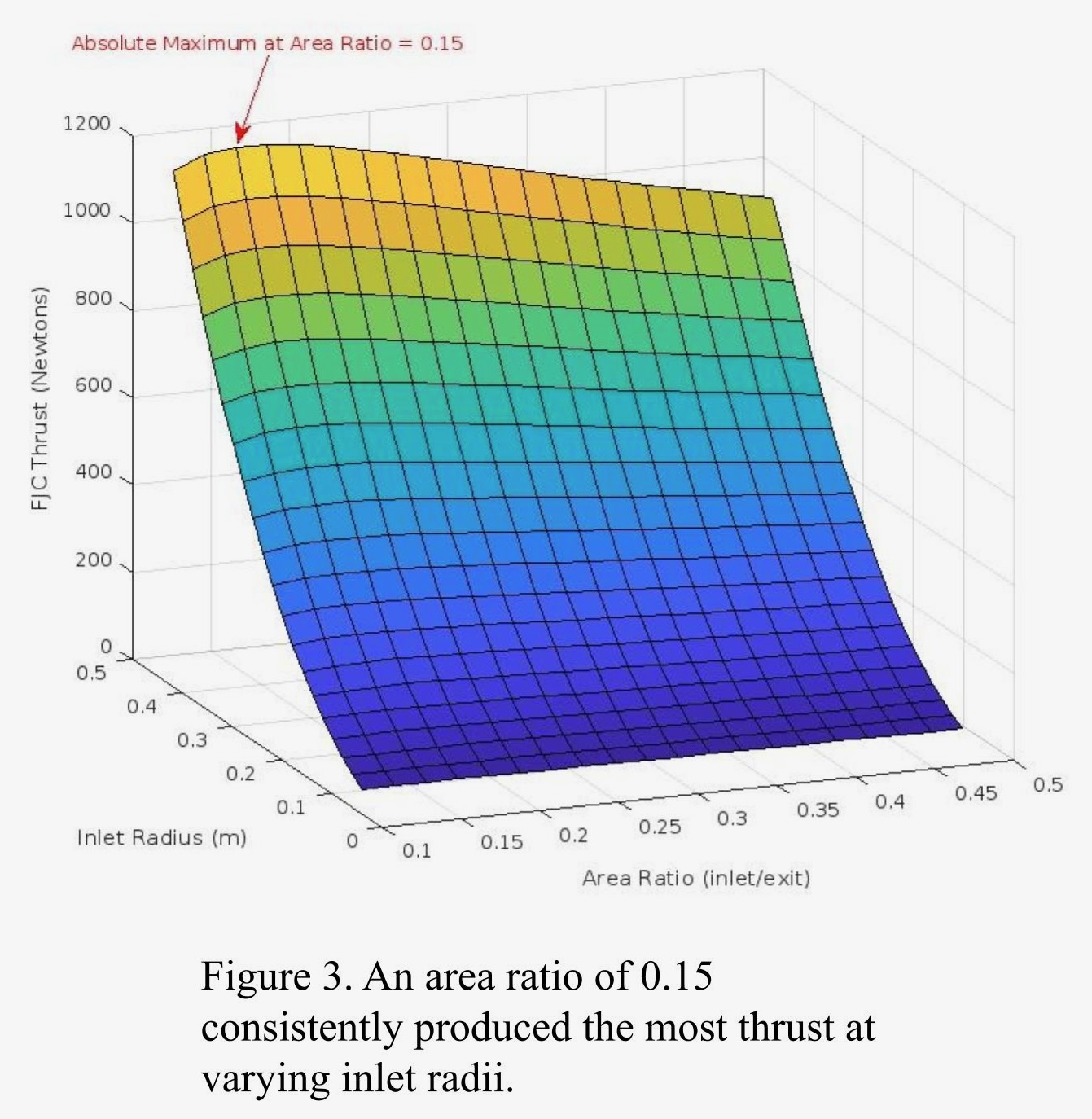
This figure reaffirms the choice of 0.15 as the FJC’s area ratio. An area ratio of 0.15 consistently yielded the most thrust for any given inlet radius. Thrust, as expected, was directly proportional to the inlet area (π * inlet radius2). We drew two conclusions from this figure: one, an area ratio of 0.15 was optimal in all cases for the FJC; two, no particular inlet radius worked better than others. We therefore chose an inlet radius of 0.35 with the intention of creating a small testbed FJC for this paper.
3.4 Study of Altitude
Having decided upon the optimal area ratio for the FJC, we investigated the effect of altitude on the current FJC design. The general trend was already known: increasing altitude should decrease FJC thrust. However, we wanted to quantify such a relationship at varying Mach speeds. We tested Machs within ±1 of the intended Mach 8 cruising speed. We also included Mach 6 to verify, in accordance with Figure 2, that the FJC produces net drag at Mach speeds below ~6.5. Figure 4 displays the effect altitude has on FJC thrust.
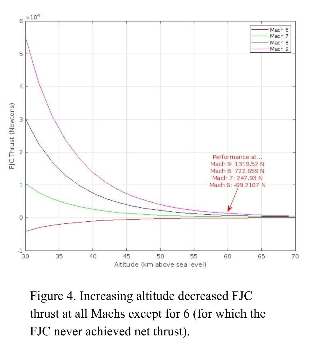
This figure correlates with the previously understood relationship between altitude and FJC thrust. It also confirms Figure 2’s conclusion that the FJC produces net drag at Mach speeds below ~6.5. Nonetheless, it provides valuable information about the boundaries of the FJC’s operating regime. Table 2 displays the respective thrust values at Machs 7, 8, and 9 as altitude increases.
| Altitude (km) | 40 | 50 | 60 | 70 |
| Mach | – | – | – | – |
| 7 | 2586.44 N | 753.964 N | 247.93 N | 90.0146 N |
| 8 | 7539.07 N | 2197.66 N | 722.659 N | 262.369 N |
| 9 | 13765.9 N | 4012.77 N | 1319.52 N | 479.066 N |
At 50 km and below, the engine has ample air for thrust. Above 50 km, FJC thrust at all Mach numbers quickly tends towards zero. Past 60 km, the gain in thrust associated with increasing Mach speed also becomes small, and at 70 km, the FJC produces <500 N for all operable Machs. Considering the FJC will propel an aircraft with relatively large cross-sectional drag (because of the variable-geometry engine assembly), we found these low thrust values too constricting for prospective cross-sectional designs. We therefore determined 60 km to be the FJC’s maximum operating altitude.
4. Discussion
4.1 FJC Design
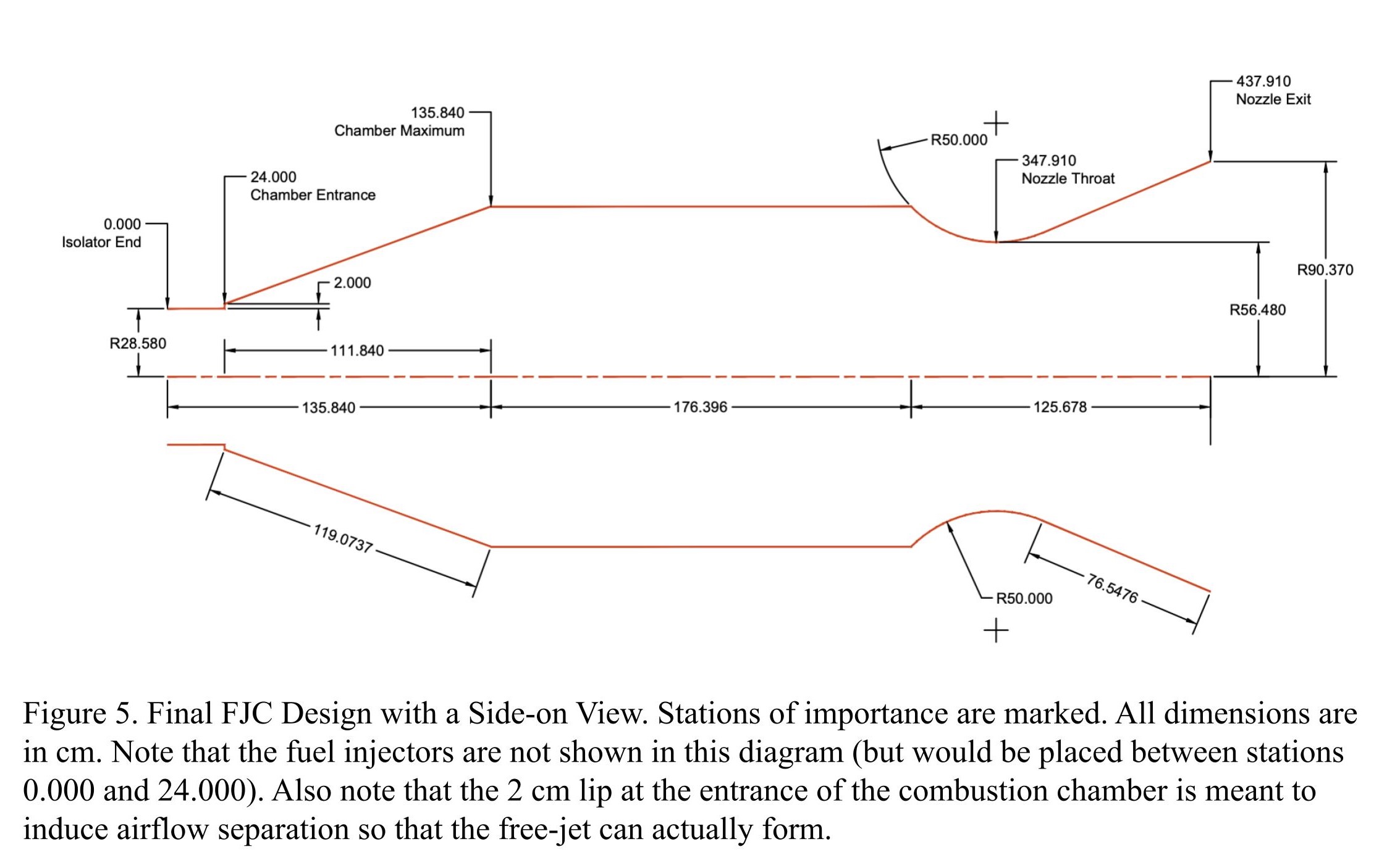
FJC design considerations are primarily dictated by the conclusions drawn from Figures 2-4. We had to decide upon the FJC inlet radius, entrance radius, combustion chamber radius, area ratio, nozzle exit radius, and nozzle throat radius. For a relatively small and unmanned test article, we settled on the studied inlet radius of 0.3500 meters. Trefny et al.’s numbers were utilized here and applied to the inlet radius of 0.3500 m to derive an FJC entrance radius of 0.2858 m3. We also derived a combustion chamber radius of 0.7145 m3. A reduction (~15%) in combustion chamber radius was made from the expected value in the interest of minimizing space requirements. We selected an area ratio of 0.1500 based on the optimization we conducted earlier in the paper. Such an area ratio results in a nozzle exit radius of 0.9037 m (and 2.566 m2 of exit area). Kurzke, based on his work with convergent/divergent nozzles, discovered the optimal nozzle expansion ratio for supersonic travel to be 1.60018. Thus, we applied the ratio to the nozzle exit radius and determined the nozzle throat radius to be 0.5648 m18. Large expansion ratios are not necessarily required for the engine itself. Because the entire assembly will be integrated into the airframe, upwards-sloping fuselage geometry behind the FJC can provide the same effect that an expanding nozzle would. Additionally, given the engine’s high-altitude operating regime, combusted air will not need to undergo much expansion to reach ambient pressure. The calculated optimal thrust of this FJC configuration at 60 km altitude will be 722.659 N at Mach 8. Do note that the geometry of the FJC is not intended to be authoritative or immediately functional, and some tweaking of the design may be necessary to achieve the intended shock-induced free-jet separation. Figure 5 depicts the FJC design with a side-on view. The following Engine Assembly Design section will explore the engine assembly design within which the FJC will be mounted.
4.2 Engine Assembly Design
We propose to mount the FJC within the variable-geometry inlet structure designed by Sanders et al. and tested by Foster et al.4,5. We decided upon the variable-cycle engine (VCE) explored by Kurzke as a method for getting the FJC up to its requisite speed18. We also put forth a novel solution to the problem of mode transition-induced unstart in the form of secondary inlets mounted on either side of the FJC. The following sub-sections qualitatively describe the aforementioned components of the design. Do keep in mind that this paper examines only the FJC, not the entire design. We place the upcoming sections to prompt future investigations.
4.2.1 Variable-Cycle Engine
According to Kurzke, an afterburning turbojet engine can perform at adequate speeds for the mode transition18. However, the optimal solution for moving from Mach 0 to Mach 4 would be to use an afterburning variable-cycle engine (VCE), which can combine the best aspects of turbojet and turbofan performance to provide excellent thrust and fuel efficiency throughout its flight regime18. This engine concept has already been developed and flown on the YF22 and YF23 test articles (predecessors to the F-22 aircraft) and is thus an already-tested design18. Using Variable-Bypass Injectors to control incoming airflow to certain parts of the engine, Kurzke’s VCE can provide consistent thrust throughout a large operating regime (both speed and altitude changes)18. Thus, the VCE is well-equipped to bring a vehicle to an operating state where FJC performance is viable.
4.2.2 Variable-Geometry Inlet
For the most part, the structure of the variable-geometry inlet structure is identical to that designed by Sanders et al. and tested by Foster et al. in NASA’s GRC 10 x 10 Supersonic Wind Tunnel4,5. There are three variable-geometry components in the design5. A low-speed inlet lip and high-speed inlet lip allow or block air to the conventional engine and the FJC, respectively5. A deflection ramp forward of both inlets changes shape to redirect oblique airflow shocks away from either the low- or high-speed inlet, depending on the current Mach5. Figure 6 provides a conception of the structure’s general shape—note that the design shown is upside-down and would be mounted on the bottom of the airframe5.
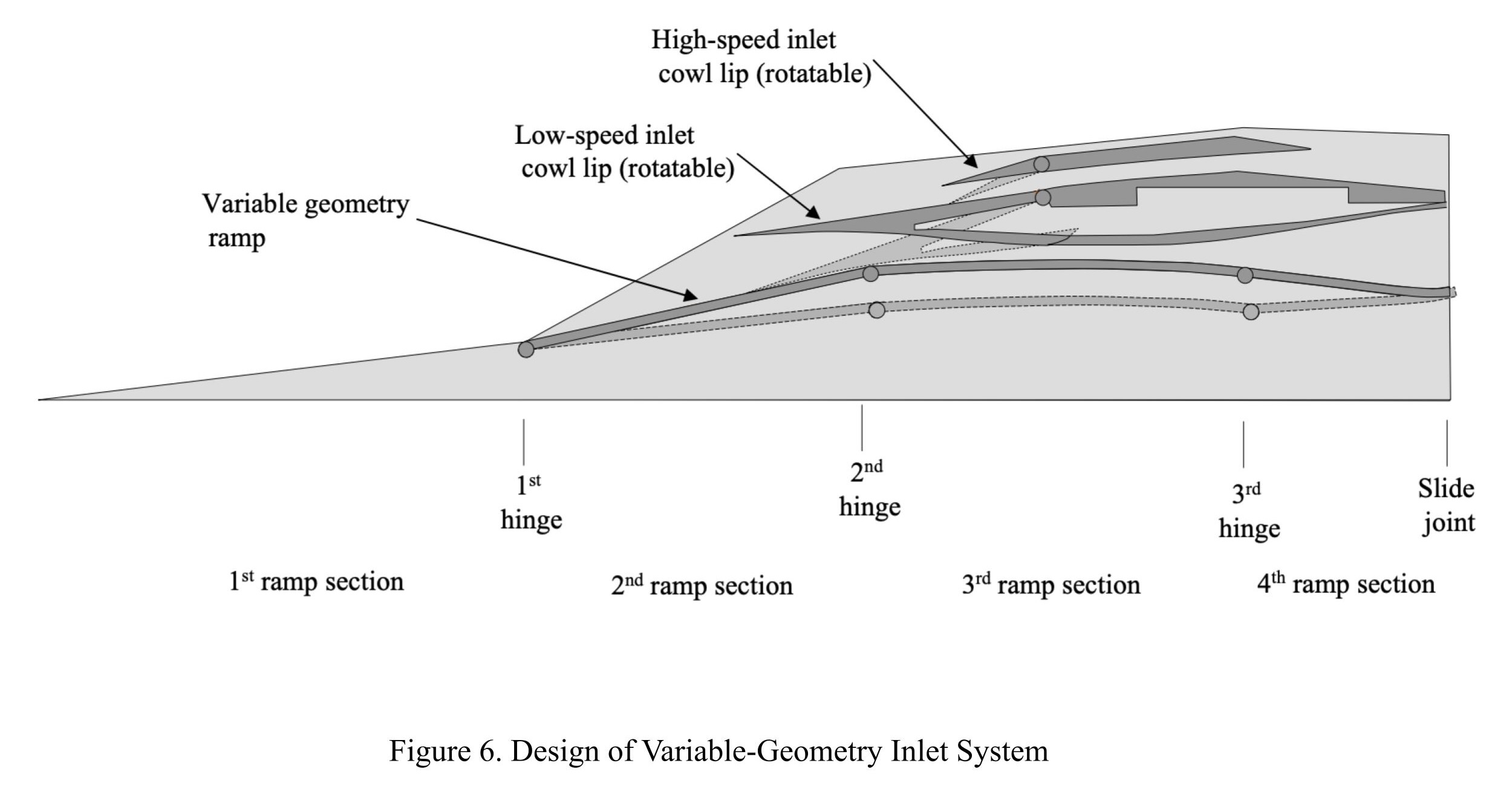
As Mach speed increases from 0 to 4, the low-speed inlet and the variable-geometry ramp both raise from their starting positions (the high-speed inlet remains open for the duration of the flight to flow air through the FJC)5. The shape they form allows for high amounts of incoming air to be compressed before reaching the turbojet/turbofan engine5. This aspect of the design assists the conventional engine in maintaining thrust up to the Mach 4 transition point. Once Mach 4 is reached and the ram effect is viable for compression, mode transition begins. The variable-geometry ramp raises to its highest position and makes contact with the low-speed inlet (which rotates down to shut off airflow to the conventional engine)5. Any oblique shocks coming from the ramp-inlet geometry are deflected past the high-speed inlet lip so that they do not interfere with incoming air5. The shape of the ramp-inlet geometry is necessary for this behavior to occur, so neither the ramp nor the low-speed inlet may be moved at these high speeds. However, this design consideration brings risks for the mode transition. Because the low-speed inlet must be fully closed before ramjet operation can begin, there will be a period of time in which neither engine is producing adequate thrust to propel the airframe. Flight instabilities will develop, potentially including engine unstart (which will impede the mode transition and overall aircraft control)19.
4.2.3 Novel Secondary Inlets
Engine unstart puts both thrust and vehicle stability at risk when it occurs19. Although Foster et al. have demonstrated smooth mode transitions with their geometry, an ideal system would be capable of maintaining thrust during the mode transition in the event that unstart does occur (in which case, the FJC could be restarted without any loss of vehicle stability)11. We propose a novel design element to solve the problem. Two variable-geometry “secondary” inlets are mounted on the engine assembly on either side of the low-speed inlet. Corresponding air injector valves allow air entering the inlets to be compressed and then merged into the low-speed flowpath directly aft of where the low-speed inlet closes. The secondary inlets shut after an upward mode transition to prevent a buildup of air in the low-speed flowpath. They may also open during a downward mode transition to facilitate early startup of the conventional engine before the main inlets move. In an alternative design, if enough air for combustion enters the conventional engine during the mode transition, the secondary inlet paths may inject air directly into the bypass region to be combusted in the afterburner.
For the sake of producing a visual design, we added two secondary inlets, each with an area of 0.10 m2, to the engine assembly. Each inlet is rectangular and has dimensions of 0.25 x 0.40 meters. Figure 7 presents a top-down view of this design scheme, including the low-speed main inlet.
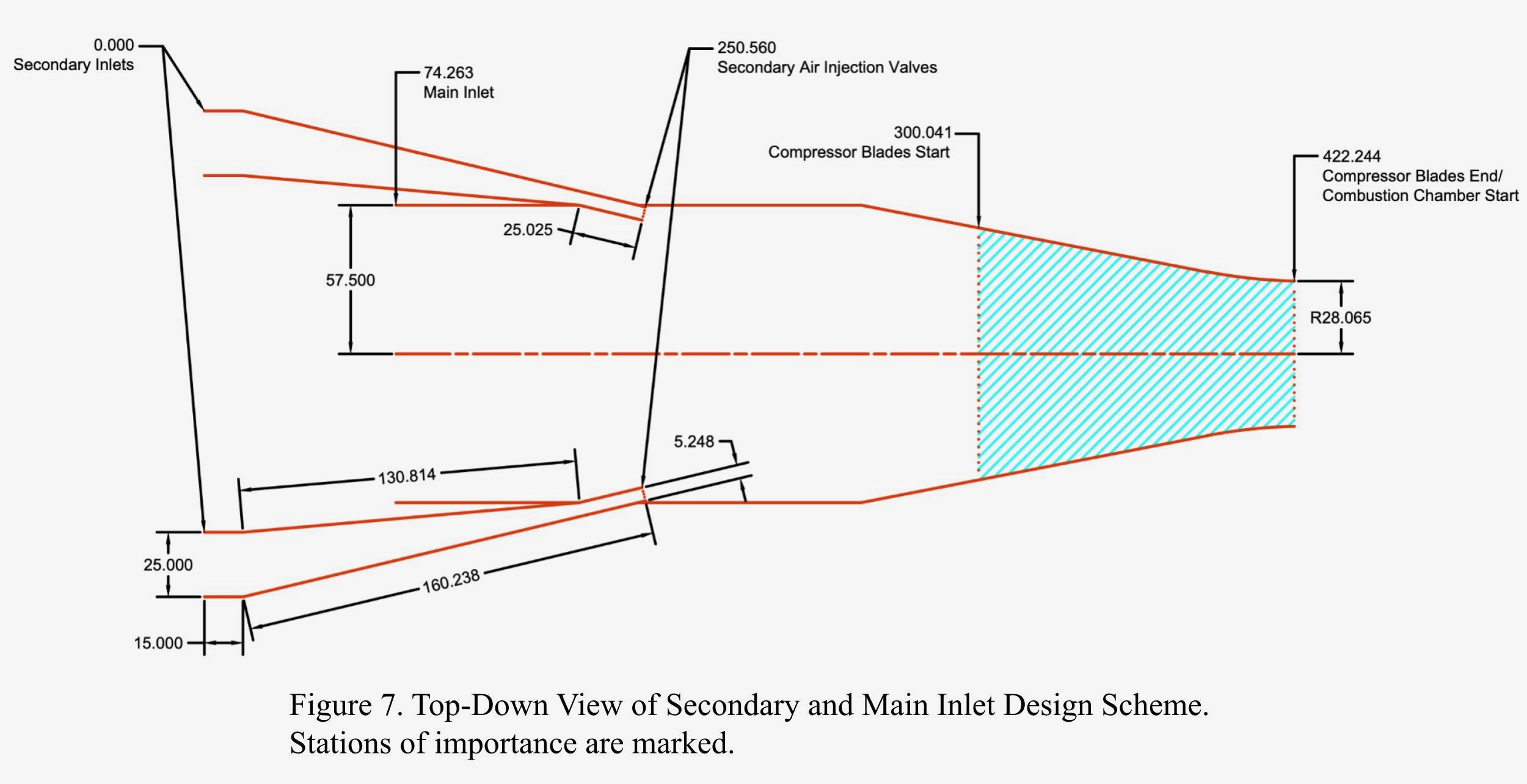
This design avoids potential backpropagation by injecting the secondary air near the start of the low-speed flow path. The only concern with such a design would be potential airflow shock structures that would form due to two angled airstreams interacting with each other. Quantitative simulations and experimentation are needed to confirm or disprove the viability of these novel inlets in providing reliable airflow to the conventional engine.
Ideally, secondary inlets such as these would be better placed on the top of the aircraft to minimize the number of complex mechanisms (four inlets, compression ramp, turbojet/VCE and FJC) in one place. However, the compression ramp blocks any airflow coming from above. Creating large airflow gaps in the ramp is less than ideal for its operation, so new inlets must be located on the sides.
4.3 Limitations
Without simulation software to examine processes such as finite-rate chemistry, heat generation, and the expansion of gasses within the engine, this paper leaves several important design considerations unaddressed. These considerations include heat load on the combustor walls, any shock formations which develop in the free-jet airstream, and airstream choking phenomena (including inlet unstarts)7,5. It is therefore not feasible to verify whether or not the final proposed FJC design would function properly in real life. The design is intended to serve as a springboard for integrating the FJC with the engine assembly, and its dimensions may be easily tweaked by prospective future researchers. However, the best attempt has been made to produce a reasonable engine design which also takes into consideration the aforementioned design aspects in a qualitative sense.
4.4 Future Directions
This paper explores an FJC design optimized for use with a novel engine assembly. The analytical relationships evaluated in this study form a foundation for future simulations to confirm the viability of the FJC itself. The desired next step would be a quantitative follow-up effort to verify and iterate upon various aspects of the design via CFD simulation. We are particularly interested in examining the thermal loads placed on the FJC at high Mach speeds.
With respect to the full engine assembly, future studies should examine how the numerous variable-geometry components—which have not been tested at a large scale—can work in unison. Furthermore, optimization of both the space and weight of the engine assembly will be needed before real-world implementation may be considered.
5 Conclusions
This paper optimizes several aspects of the FJC—a unique engine which can switch from ramjet to scramjet operation without a change in geometry3. We present a refined FJC design meant to fit into a larger engine assembly. We also qualitatively explore the configuration of this engine assembly. A variable-geometry inlet feeds air to the FJC and a conventional engine, changing airflow to each one to induce mode transitions4,5. Two secondary inlets, novel design components, allow for airflow to the conventional engine during a transition to minimize potential flight instabilities. The entire engine assembly is capable of operation from sea level to 60 km altitude, at a range of speeds from standstill to Mach 8+. This design’s upper limit may be far beyond that, but great advances are needed before pushing out of an already groundbreaking flight regime is possible. Nevertheless, the fundamentals of the system now exist. Every step forward in hypersonic research brings the design closer to reality.
Acknowledgements
I would like to thank Dr. Michel Lacerda for his mentorship and guidance throughout all the stages of this paper.
References
- G.S. Lee, T. Lee. Fluid and combustion dynamics in dual-mode scramjets. Frontiers in Aerospace Engineering. 1,1-7 (2023). [↩] [↩]
- Bartolotta, P.A., Buchen, E., Engelund, W.C., Huebner, L.D., Moses, P.L., Schaffer, M., Voland, R.T., Voracek, D.F., & Wilhite, A.W. (2011). Horizontal launch: a versatile concept for assured space access. National Air and Space Administration. https://ntrs.nasa.gov/citations/20120000791 [↩]
- Trefny, C.J., Dippold, V.F., & Yungster, S. (2017). Dual-mode free-jet combustor [Paper presentation]. International Symposium on Air Breathing Engines (ISABE) Conference 2017, Manchester, United Kingdom. https://ntrs.nasa.gov/citations/20170008733 [↩] [↩] [↩] [↩] [↩] [↩] [↩] [↩] [↩] [↩] [↩] [↩] [↩] [↩] [↩] [↩]
- Foster, L.E., Saunders, J.D., Sanders, B.W., & Weir, L.J. (2012). Highlights from a Mach 4 experimental demonstration of inlet mode transition for turbine-based combined cycle hypersonic propulsion [Paper presentation]. 48th Joint Propulsion Conference and Exhibit, Atlanta, Georgia, United States. https://ntrs.nasa.gov/citations/20130003353 [↩] [↩] [↩] [↩] [↩] [↩]
- Sanders, B.W., & Weir, L.J. (2008). Aerodynamic design of a dual-flow Mach 7 hypersonic inlet system for a turbine-based combined-cycle hypersonic propulsion system. (Publication No. TRR-121507). https://ntrs.nasa.gov/citations/20080030791 [↩] [↩] [↩] [↩] [↩] [↩] [↩] [↩] [↩] [↩] [↩] [↩] [↩] [↩] [↩]
- N.R. Hall. Ramjet propulsion. www.grc.nasa.gov/www/k-12/airplane/ramjet.html. (2000). [↩] [↩] [↩] [↩]
- Trefny, C.J., Dippold, V.F., & Yungster, S. (2017). Dual-mode free-jet combustor [Paper presentation]. International Symposium on Air Breathing Engines (ISABE) Conference 2017, Manchester, United Kingdom. https://ntrs.nasa.gov/citations/20170008733 [↩] [↩] [↩] [↩]
- N/A. X-43A Hyper-X. www.nasa.gov/reference/x-43a/#hds-sidebar-nav-5. (2024). [↩]
- N/A. X-51A Waverider. www.af.mil/About-Us/Fact-Sheets/Display/Article/104467/x-51a-waverider/. (2011). [↩]
- Trefny, C.J., & Dippold, V.F. (2010). Supersonic free-jet combustion in a ramjet burner [Paper presentation]. 46th Joint Propulsion Conference and Exhibit, Nashville, Tennessee, United States. https://ntrs.nasa.gov/citations/20110000537 [↩]
- Foster, L.E., Saunders, J.D., Sanders, B.W., & Weir, L.J. (2012). Highlights from a Mach 4 experimental demonstration of inlet mode transition for turbine-based combined cycle hypersonic propulsion [Paper presentation]. 48th Joint Propulsion Conference and Exhibit, Atlanta, Georgia, United States. https://ntrs.nasa.gov/citations/20130003353 [↩] [↩] [↩] [↩] [↩] [↩] [↩] [↩] [↩] [↩]
- Riggins, D., Tackett, R., Taylor, T., & Auslender, A. (2006). Thermodynamic analysis of dual-mode scramjet engine operation and performance [Paper presentation]. 14th AIAA/AHI International Space Planes and Hypersonics Systems and Technologies Conference, Canberra, Australia. https://ntrs.nasa.gov/citations/20070000536 [↩] [↩] [↩] [↩] [↩]
- N.R. Hall. Earth Atmosphere Model – Metric Units. www.grc.nasa.gov/www/k-12/airplane/atmosmet.html. (2000). [↩] [↩]
- N.R. Hall. Ramjet / Scramjet Thrust. www.grc.nasa.gov/www/k-12/airplane/ramth.html. (2000). [↩] [↩]
- Svensson, G. (2020). 1D Scramjet Model [Master’s thesis, Massachusetts Institute of Technology]. DSpace@MIT. [↩]
- Svensson, G. (2020). 1D Scramjet Model [Master’s thesis, Massachusetts Institute of Technology]. DSpace@MIT. https://dspace.mit.edu/bitstream/handle/1721.1/129141/1227504735-MIT.pdf?sequence=1&isAllowed=y [↩]
- K. Chiu, A. Dosev, D. Gupta, T. Hong, N. Kirk, R. Madduluri. Hypersonic propulsion systems review. World Scholars Review. N/A, N/A (2024). [↩]
- Kurzke, J. (2010). The mission defines the cycle: turbojet, turbofan and variable cycle engines for high-speed propulsion. NATO Research and Technology Organization. https://apps.dtic.mil/sti/tr/pdf/ADA596249.pdf [↩] [↩] [↩] [↩] [↩] [↩] [↩]
- S. Im, H. Do. Unstart phenomena induced by flow choking in scramjet inlet-isolators. Progress in Aerospace Sciences. 97, 1–21 (2018). [↩] [↩]


