
Abstract
The efficiency of robotic prosthetic hands depends heavily on how mechanical power is transmitted from the motor to the actuation method. There are two common approaches, tendon-driven actuation and rigid linkage-driven actuation. Each method offers different advantages: tendon-driven systems often are more lightweight and allow for compliant motion, while linkage systems give more structural stability. Although both mechanisms are widely used in prosthetic applications, their energy efficiency during static holding tasks has not been directly compared in controlled experiments. This study compares the holding force, power consumption, and force-to-power (F2P) ratio of a single tendon-driven and linkage-driven prosthetic finger during static holding under very similar conditions. To isolate the actuation methods as the main variable, two single finger prosthetic models were designed with identical geometry, materials, and servo motors, with the variable changing being the actuation system. Both designs were modeled in SOLIDWORKS, simulated through finite element analysis, fabricated using PLA 3D printing, and tested under repeated load. During testing, each finger was held at a fixed angle while force output was measured using a luggage weight scale and power draw was measured using an ammeter while held at a constant voltage. From the testing, the linkage-driven model had a higher average holding force of 30.94 N, compared to the 20.97 N of the tendon-driven model. However, the tendon-driven model consumed substantially less power, averaging 1.78 W compared to 8.15 W for the linkage-driven design. This led to a higher force-to-power ratio for the tendon-driven mechanism, with an average F2P ratio of 11.83 N/W compared to 3.81 N/W for linkage-driven mechanisms. These results indicate that the tendon-driven produced a higher F2P ratio and lower power consumption, whereas the linkage-driven design produced greater maximum holding force under the tested conditions.
Introduction
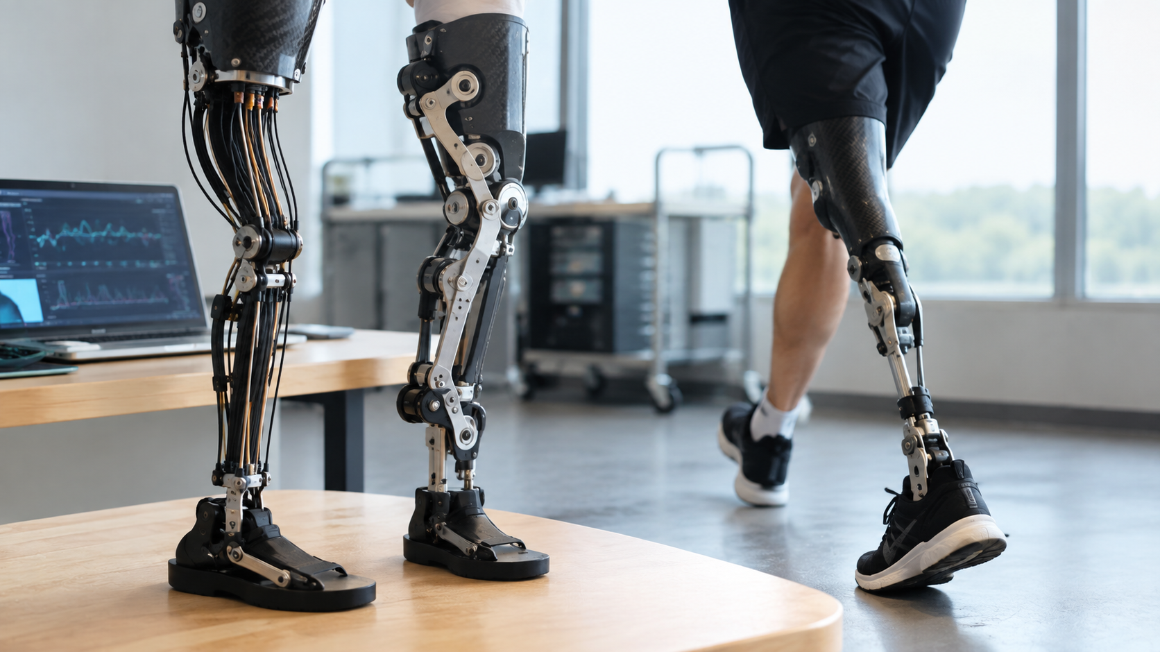
Every day in the United States, over 500 people have a limb amputated or an appendage removed1. This severely limits their ability to do simple tasks, such as tying their shoes, which is a recurring action in their daily routine2. Prosthetic appendages– which are replacements for arms and legs– have been created to fill this gap and regain their ability to perform various actions. Rudimentary prosthetics, such as static dummy hands, have minimal utility and are typically for “cosmetic us[e]” or as a way to avoid public attention2. Robotic prosthetics, however, serve a more functional purpose and allow users to restore functionality to their limbs and, in some cases, gain more than they had before. These appendages are commonly referred to as “bionic [arms]” as they include actuators and sensors paired with a processing unit to provide a much wider range of use cases3. One of the most important aspects of bionic devices is the actuation methods to move and control components. A variety of designs have been implemented to control prostheses, with each having its own benefits and weaknesses. Some of the most common actuators include tendon-driven actuators and rigid linkages.
Background
Actuation methods for prosthetics have various benefits and difficulties depending on how they function. While many designs have merit and applicability, they are often limited to specific use cases that are difficult to translate from one application to another. Some of the most common methods for actuating these mechanisms include tendon-driven joints and rigid linkage connections4,5,6.
Tendon-Driven
The most prevalent method for actuating prosthetic appendages –specifically fingers on bionic hands– is through cable-driven systems, also called tendon-driven systems7,8. These systems function through a series of pulleys, springs, and rotational motors, which can provide individual finger actuation. By reeling in the cable through the motors, the string length gets smaller and results in the finger curling up.
This approach has many merits that make it very common. Primarily, tendon-driven systems allow the majority of the actuation system’s weight to be situated away from the object it is actuating9. This gives the user greater comfort as the majority of discomfort that amputees have from prosthetics is a result of heavy weight6,10. Williams and Walter developed an over-actuated prosthetic hand that used small motors within the fingers to form the grasp while a different tendon system made greater forces that correlated to a stronger grip9. Because the heavier actuators could be positioned in the forearm away from the fingers, the design could resemble a natural arm more because the bulk of the servos do not need to be put into hand which is much smaller. However, Williams and Walter also reported that the fingertip force was lower than the theoretical design forces include tendon friction and off axis routing9. This shows that the tendon-driven systems can lose some force between the actuator and the fingertip depending on the path. To reduce this effect, tendon material and routing can be made to reduce the amount of unnecessary changes in the tendon path or make the path straighter.
To find the effect that tendon routing has on the behavior of the tendon-driven designs, Zhou et al. compared different routing configurations that found the selected path affected tension, joint motion, and friction11. Designs that made a linear path towards the end of the fingertip were able to reduce the amount of friction compared to those which had different angles of channels to move the string11. Essentially, a fixed and repeatable path can greatly reduce variation11.
Another advantage of tendon-driven fingers is that the force can be transferred between different systems without needing a motor at every joint. Tokunaga et al. developed a tendon-driven prosthetic system where one motor could control multiple tendons through transmission12. Tokunaga et al.’s study shows how the tendon-driven actuation can reduce the number of motors needed in a prosthetic hand. However, for the purposes of this study, only one finger was modeled rather than many.
Rigid Linkage-Driven
Rigid linkage-driven connections are also another common way to power bionic appendages. Instead of the flexible and compliant features of tendon-driven prosthetics, rigid linkages provide a strong structure and a greater degree of precision due to their fixed distances. These qualities make rigid linkages effective in larger limb situations where the amount of strength a given joint possesses is more important than its ability to deform in response to an object. However, some research is still able to achieve higher deformation levels using passive linkages instead of active, but for this study this is not explored13,14. Common applications of a rigid linkage in prosthetics include hip structures and legs, where an increased amount of structural support is needed to sustain the heavy loads4,15. For example, four- bar linkages can give mechanically constrained finger movements and can hold heavy loads even when 3D printed15. Additionally, while simple two bar linkages can trace fairly rudimentary shapes, using more complex linkages, a more natural path can be created with crossed four-bar mechanisms16.
While the strength properties of these actuators are beneficial under the right conditions, there are many disadvantages in fringe scenarios that may remove them as an option for effective powering. One key downside to rigid designs is their inability to absorb heavy shock loads and adjust to different situations17. Because of their stiff body, any sudden force acting on the structure is applied directly on all the joints and into the rigid links connecting them. These effects can be even more detrimental under certain scenarios if the forces act in a direction that the link cannot support or handle. Overly strong torques on connections can overload them past their bearing limit and cause them to fracture. Additionally, Difonzo et al. found that the inability to adjust to different situations can reduce the adaptability in some prosthetic fingers because the contact in one portion can limit movement in the rest of the joints18. More complex linkage structures can improve the amount that the actuation can adapt but they greatly increase the complexity. Finally, linkage-driven mechanisms can also be very effective in making coordinated trajectories. This is accomplished using multiple connecting mechanisms which rotate about each other to make a certain motion. In one study, Kim et al. developed a robotic hand that used a bell-crank with four-bar linkages to make more adaptable motion19. While he was able to make the transmission more “efficient” compared to standard actuator designs, including a bell-crank made the design much more complicated and difficult to mass produce19.
Gap
Although extensive research exists on prosthetic actuation systems, much of the current literature focuses on the performance of the actuators rather than directly comparing their functionality, adaptability, and user comfort. Studies have shown the benefits of tendon-driven systems in achieving flexibility and lightweight design7,8 and the precision and strength of rigid linkages for high load situations4. However, few studies have examined how these actuation types differ in performance across practical prosthetic use cases or how they affect long-term performance. This study seeks to create an understanding of which actuation approach is the best balance of force output to power consumption, thus leading to the question: How do tendon-driven and linkage-driven prosthetic fingers compare in holding force, power consumption, and static holding force per unit of electrical power under very similar testing conditions?
Hypothesis
Little foundational research exists on which to base a definitive hypothesis, but studies on prosthetic actuation offer some insights. Research by Smidt and Bicknell, and other researchers shows that tendon-driven prosthetic hands tend to be more flexible and adaptable due to their lightweight design and cable motion8. Botros and researchers found that strength and precision are found in rigid linkage systems4. Given these findings, it is expected that linkage-driven mechanisms will have a greater holding force because of its rigid structure. On the other hand, the tendon-driven mechanism is expected to use less power during static holding. Therefore, it is expected that the tendon-driven systems will produce a higher force-to-power (F2P) ratio.
Methodology
Overview
This experimental approach is common among established mechanical testing methods in prosthetic and robotic hand research20. By using a standard testing model and including repeated measurements, this method provides a reliable structure for analyzing actuation methods. Once the measurement structure for analyzing the data collected was established, the values were held consistent by making sure the setup of the experiment had no backlash or tolerance issues and everything was exactly where it needed to be. This was tested by shaking the platform that the experiment was conducted on and looking for any noticeable loose parts or vibrations.
To properly quantify and qualify the holding strength of tendon-driven versus linkage-driven prosthetic hands, two functionally equivalent prosthetic finger models needed to be designed and constructed. A single finger design was selected to isolate the effects of changing the actuation method while also minimizing external variables that could potentially form from multiple fingers. Both fingers were designed with very comparable geometries, materials, and servos so that the only intended difference between the two models was the actuator. To achieve this, while in the Computer Aided Design (CAD) software, the initial base for the hand was made and then changes were made to include actuation specific qualities such as a channel for the tendon design and mounting hole for the linkage design. After the two models were built, both prosthetic models were tested to track mechanical strengths as well as electrical efficiencies by creating a measurement of force exerted per unit of power drawn so that the two models could be effectively compared. This approach reduced the effect of external variables to ensure the primary factor adjusting the results was the actuation method.
Once the broad strategy was complete, to answer the research question, a quantitative experimental design was made to compare the holding strength and F2P ratio between the two systems. This involved applying a controlled load to a common point on each finger, which was done by using a simple digital luggage scale. By testing both prosthetic fingers under identical conditions, the experiment produced quantitative data that can make a clear comparison between the tendon-driven design and the linkage-driven design. Setting the load as a consistent value rather than changing other programming constants to adjust the settings was chosen because it could better show the high end of total force that each actuation method could exert.
Materials and Equipment
To conduct the study, the prosthetic finger models were designed using SOLIDWORKS 2024 and analyzed using the SOLIDWORKS Simulation finite element analysis module. Physical components were fabricated using an Anycubic Vyper 3D printer with polylactic acid (PLA) filament. Each finger used one servo and was controlled by an Arduino Uno R4 Minima microcontroller. This was all powered by a 9 V power supply. The servos were rated at 9 kg cm at 8.4 V. However, given that the servos were powered by an Arduino microcontroller, the max voltage provided was closer to 4.8 V which gave a stall torque of 6.5 kg cm. The current draw was measured using an ammeter placed in series between the power supply and servo motor. Load bearing was applied using a digital luggage scale to make sure the force was controlled and repeatable. The tendon-driven design used a low-elasticity cord through internal channels to transmit force.
CAD Design of Prosthetic Finger
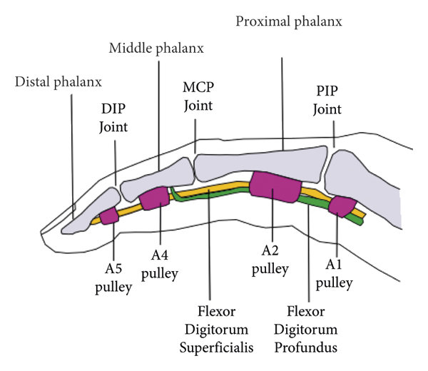
Both prosthetic fingers were first modeled in SOLIDWORKS 2024 using a feature-based workflow. The finger geometry was designed to be simple in shape but model the scaling of a single degree of freedom finger joint with a proximal phalanx, a distal phalanx, and a rotational joint. A visualization of a generic finger structure is presented in Figure 1.
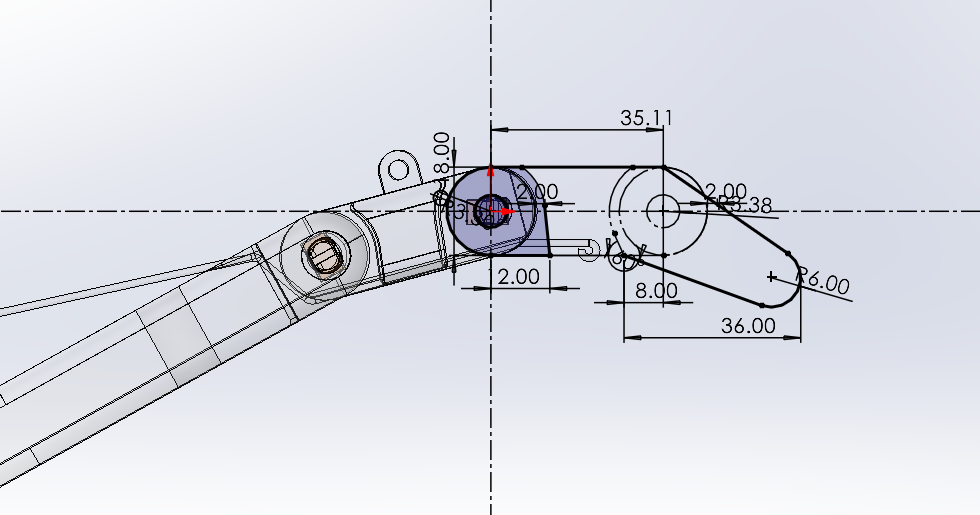
The dimensions were directly copied over across models to keep attachment points the same between the different actuators.
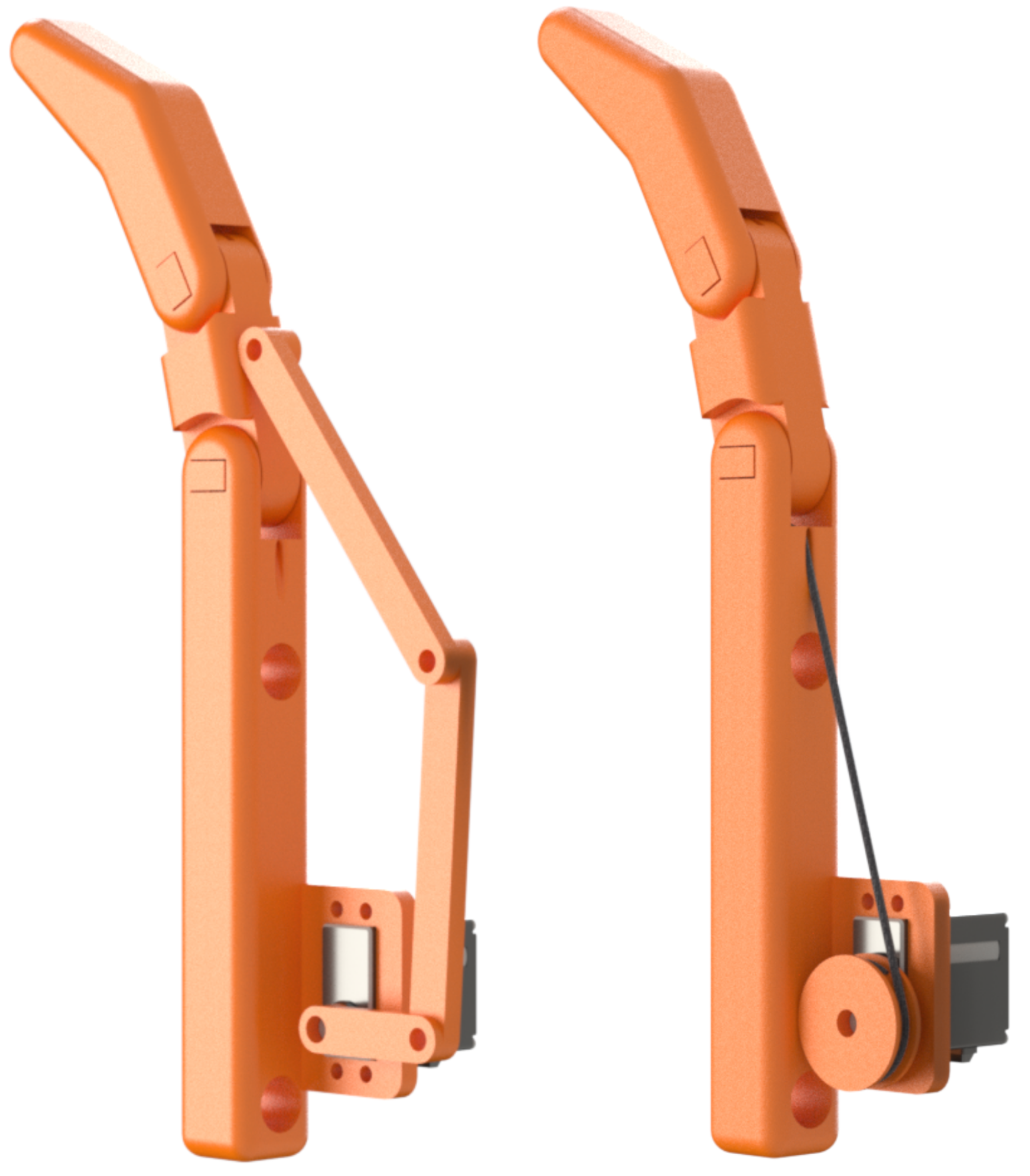
The linkage-driven model was designed with a rigid mechanical linkage directly connected to the servo spline to the distal phalanx which creates a fixed application of torque across the motion. On the other hand, the tendon-driven model included an internal routing channel which houses the string material wrapped around each joint to transfer torque and rotate joints. Outside of the actuator interfacing, all geometries were constant.
Finite Element Analysis
After completing the CAD models, material properties were assigned within the SOLIDWORKS Simulation software. Primarily, the FEA was conducted to ensure the finger could support the expected weight. This ensured there would be no material failures later. The structural components were given a material property like 3D-printed PLA plastic which fasteners were modeled as steel. The contact conditions between the surfaces were defined to give the model an understanding of how the finger is connected in real life which aids in simulating realistic finger movement.
For the linkage-driven and tendon-driven designs, the two finite element analysis (FEA) simulations were done separately. In both the simulations, the actuator was held with a torque value equivalent to the holding strength of the servo at that max current draw. Then, at a fixed point along the finger, a force was applied in varying degrees to understand the differences in displacement depending on the amount of force. This was primarily done to test if the model would hold up under some of the expected loads or if the model would break.
In this FEA, material properties were based on the materials used in the physical prototypes. The printed structural components were made using ABS PC properties from the SOLIDWORKS Materials Library because the qualities closely resembled those of PLA. For the joint hardware, the material was selected based on the fastener material in the prototype. The contact conditions were defined between the parts that were fixed around each other and adjacent to one another.
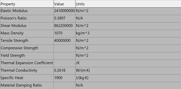
The stress distribution, displacement, and deformation were analyzed for each design to find the expected mechanical behavior and failure points before assembling the models.
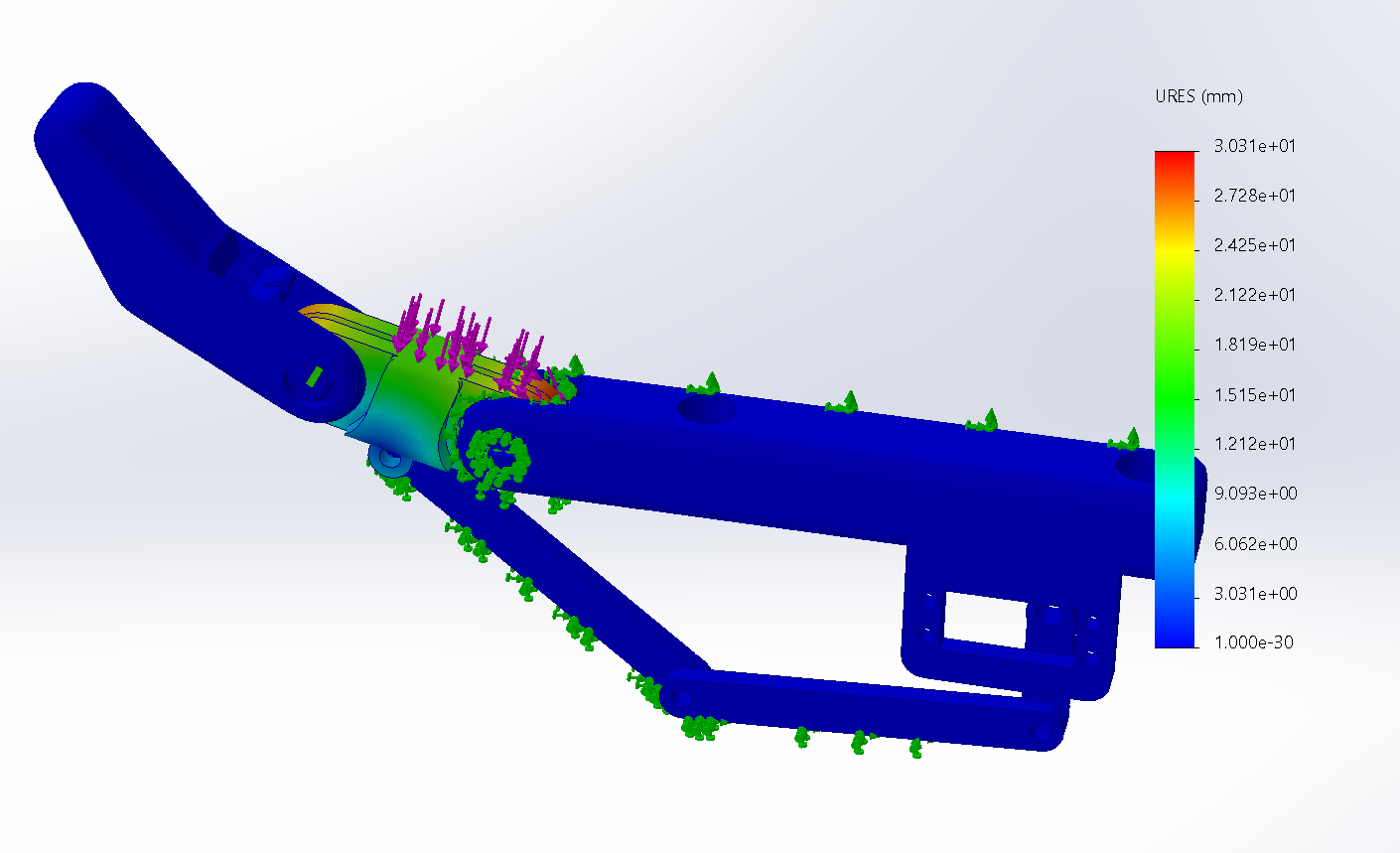
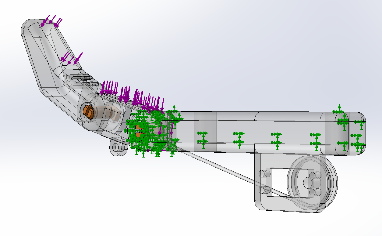
For the tendon-driven design, modeling some of the tension forces within the cable was difficult considering the material properties of the string. So, instead the approximated torques and forces were calculated through the mechanism, and the torque was applied to the axis of rotation for the finger. This process was simpler in the linkage-driven finger as there were no obscure material properties or tension factors, so for this system a torque was applied to the end of the linkage which caused rotation and the holding of the linkage. From the servo’s product page, the stall torque was approximately 6.5 kg·cm at 4.8 V. This torque was then taken into consideration given the size of the pulley (radius of 10mm) and the final torque was applied to the joint. However, this process was primarily testing the ability of the fingers to hold up against the heavy weights rather than to predict what could happen in the experiment.
Once the forces were defined, the system had to be meshed. For this the refinement was set to the finest possible density so that the model could run at the highest possible accuracy.
Mechanical Assembly
After simulating the mechanisms, both prosthetic fingers were created using an Anycubic Vyper, a fused deposition modeling (FDM) 3D printer using PLA filament. A key design consideration when creating a model for 3D printing is to account for tolerance and precision in the final product. After referencing a study conducted by Eldessoki and researchers, the exact tolerance needed in each step of the model could be predicted22. Eldessoki’s group research is perfectly aligned with the construction of this study as the material of the filament, 3D printer, and CAD software are the same as the ones used in this study22
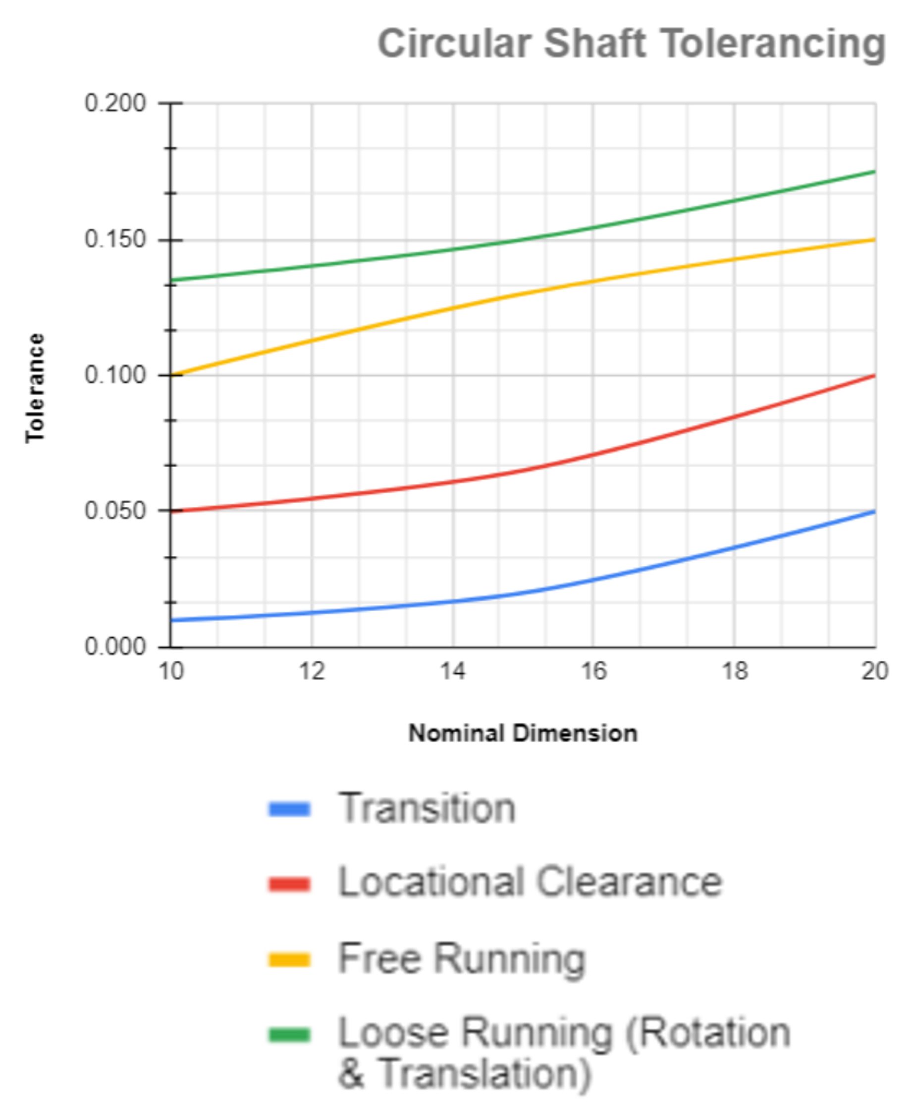
To further the similarities in the models, identical print settings were used for each design to eliminate the fabrication as a step of variance.
Once all the required parts were manufactured, the parts were assembled according to the CAD model using simple 3D printed clip in pegs as nuts and bolts rather than using the metal counterparts. This allowed all the tolerance and spacing to be controlled by the model rather than having to adapt to an external system.
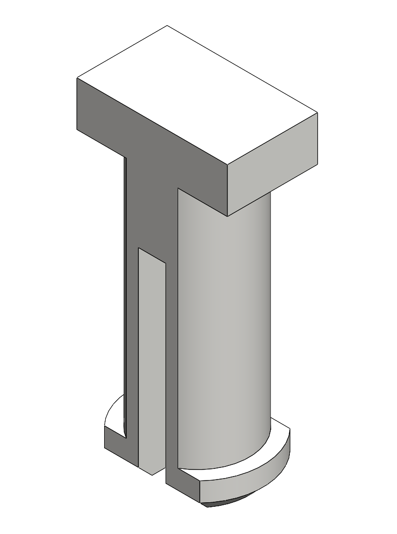
The finger was then mounted into a vice that could hold the body at a fixed position while the rest of the study was conducted. This ensured the finger could not move and that any force from the weight was being held only by the torque from the servo.
The linkage-driven finger was assembled by first mounting all the necessary electronics externally to the body of the finger except the servo which was integrated into the design. Afterwards, the servo was coupled to a 8mm hex shaft that could rotate a fixed link to achieve around 35 degrees of actuation at the axis of the servo spline. This angle was selected as a practical position rather than being a biomechanically derived setting. The purpose was to keep both mechanisms at the same repeatable position so their force output and power consumption could be compared. This link was then connected to a second line which was attached between the first line and the distal phalanx. All links were connected by using a simple screw and a nylon locknut which was ideally tightened to give enough tolerance for smooth rotation while constraining the links effectively. It was crucial that locknuts were used in this situation because micro-vibrations in the mechanism could loosen nuts that did not have the nylon seal.
When it came to the tendon-driven assembly, channels for the string were made in the model ahead of time to give the cord space to be routed properly. After traveling through the channels, the string was then tied down to a point under the distal phalanx, like the linkage-driven design. Vectran rope was perfect for this use as a study by Langston and Jones in collaboration with NASA showed it had the least amount of creep, making sure it did not lose tension over time23. While the tendon-driven model developed would not run for the extended duration that the strings were tested at, it is important to know they can retain their F2P ratio over time23.
Electrical Control
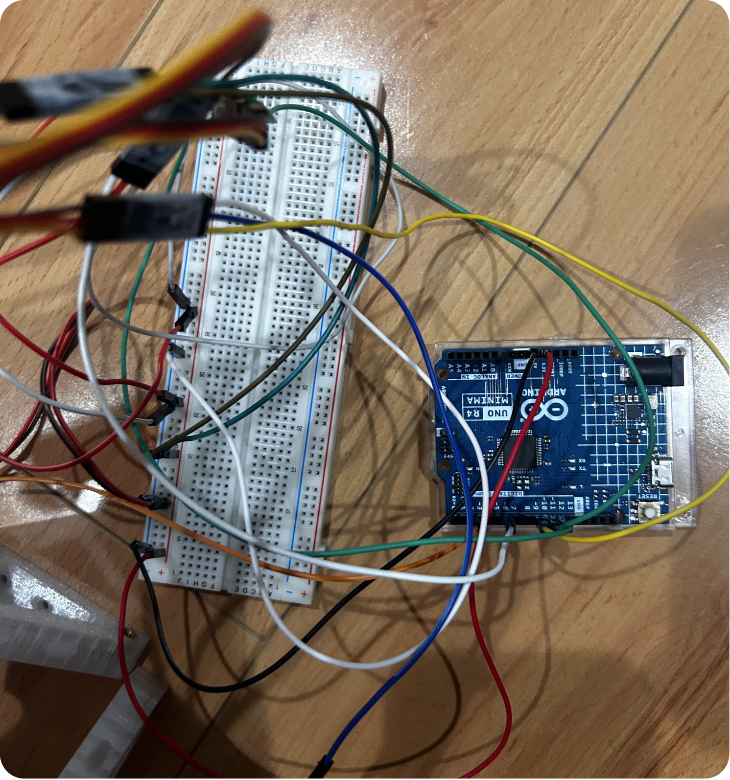
Each prosthetic finger was actuated using the same servo motor and controlled by an Arduino Uno R4 Minima microcontroller. The Arduino was programmed to drive the servo to a fixed angle of 35 degrees and hold the position under load. The servo control was kept identical between designs and ensuring equal amounts of current flow. This angle was chosen to keep a consistent angle position and to ensure that the finger was not so horizontal that it would bend down and cause the force to fall.
An ammeter was placed in series between the power supply and servo to measure the real-time current draw during testing. These values were recorded to see when the values spike and the displacement at various current draws. To maintain a level of similarity to real-world scenarios, the total current drawn was measured rather than just the additional current from the load. Only looking at additional current instead of the sum of the additional plus idle would make the quantity smaller than real-world conditions.
Data Collection
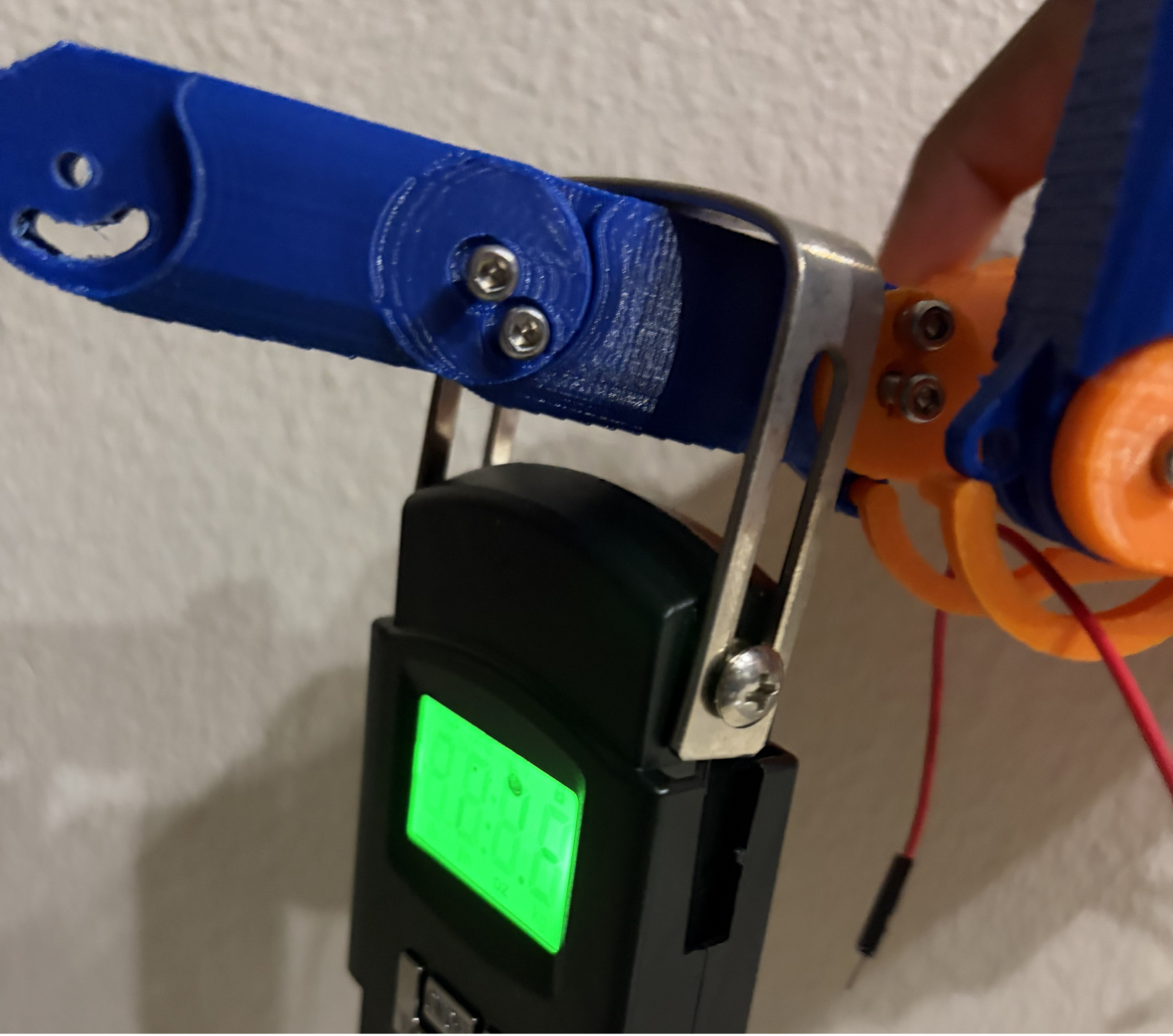
To measure the displacement, a background was placed behind the finger on a dedicated mount. Then using camera detection, the displacement could be found. The controlled loads were placed at a fixed distance which is as close as possible to the position in the simulation. To control the amount of force exerted, a digital luggage scale was used to reach an exact force value. Multiple trials were conducted for each actuation to reduce the amount of variance.
Results
| Trial | Tendon Force (N) | Linkage Force (N) | Tendon Power (W) | Linkage Power (W) | Tendon F2P Ratio (N/W) | Linkage F2P Ratio (N/W) |
| 1 | 20.8 | 29.7 | 1.7 | 7.9 | 12.24 | 3.76 |
| 2 | 21.3 | 31.2 | 1.9 | 8.4 | 11.21 | 3.71 |
| 3 | 19.9 | 30.5 | 1.8 | 8.1 | 11.06 | 3.77 |
| 4 | 22.1 | 32.0 | 1.6 | 7.8 | 13.81 | 4.10 |
| 5 | 20.5 | 28.9 | 1.9 | 8.7 | 10.79 | 3.32 |
| 6 | 21.7 | 33.1 | 1.8 | 8.2 | 12.06 | 4.04 |
| 7 | 20.2 | 30.8 | 1.7 | 7.6 | 11.88 | 4.05 |
| 8 | 22.4 | 31.5 | 1.8 | 8.3 | 12.44 | 3.80 |
| 9 | 19.8 | 29.4 | 1.9 | 8.5 | 10.42 | 3.46 |
| 10 | 21.0 | 32.3 | 1.7 | 8.0 | 12.35 | 4.04 |
| Average | 20.97 | 30.94 | 1.78 | 8.15 | 11.83 | 3.81 |
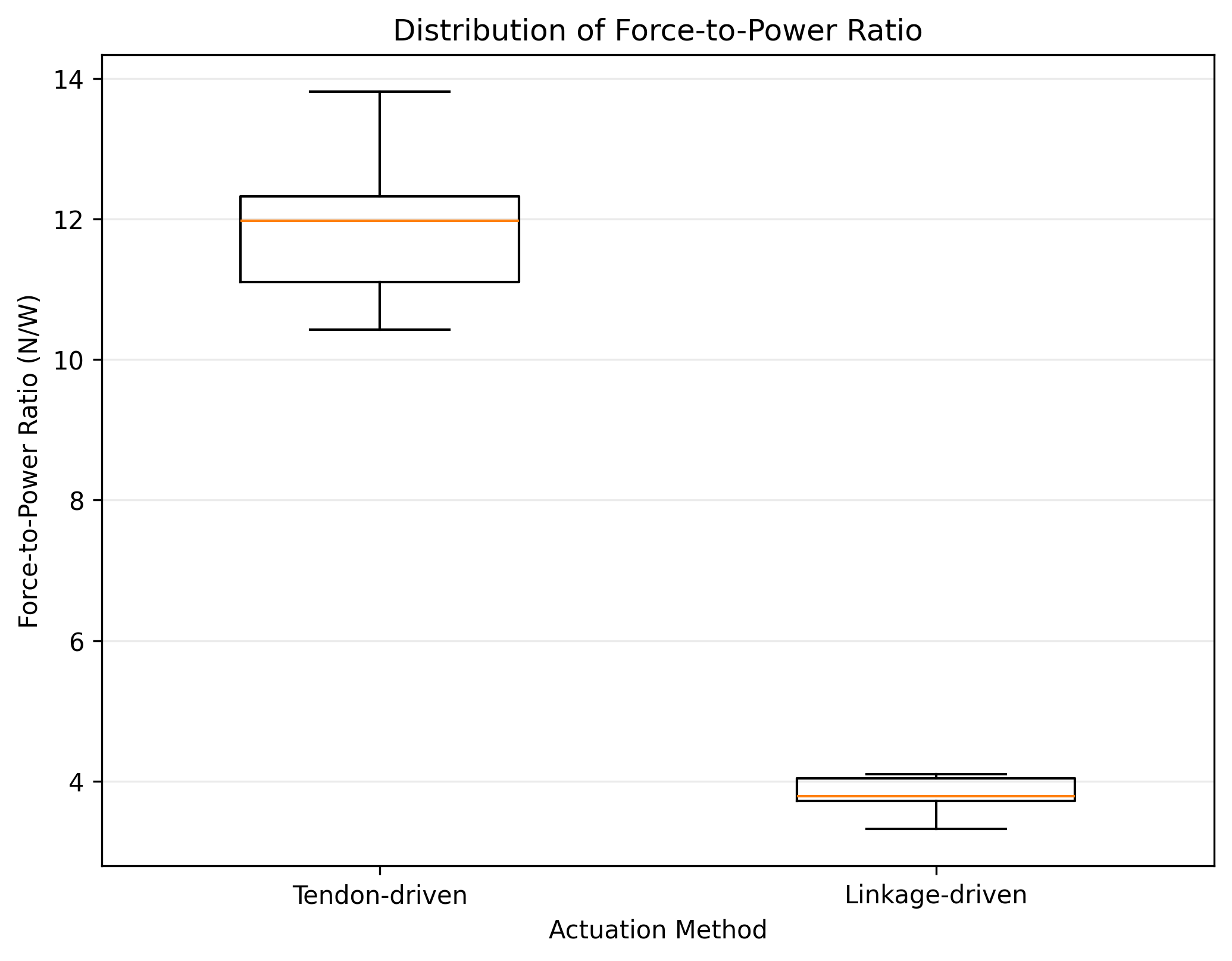
To better compare the performance of the two systems, I calculated the force-to-power ratio of the two systems. The tendon-driven mechanism demonstrated a higher average efficiency (M = 11.83, SD = 0.99), while the linkage-driven mechanism showed a lower average efficiency (M = 3.80, SD = 0.26). This shows that the tendon-driven system produced more holding force per unit of energy consumed.
Across the 10 trials, the linkage-driven prototype had a mean holding force of 30.94 N (SD= 1.35 N) compared to a holding force of 20.97 N (SD = 0.90 N) for the tendon-driven prototype, giving a difference of 9.97 N. The linkage-driven prototype also used more electrical power with an average of 8.15 W (SD = 0.34 W) compared to the 1.78 W (SD = 0.10 W) for the tendon-driven prototype. On the other hand, the tendon-driven prototype had a higher F2P ratio, averaging 11.83 N/W (SD = 0.99 N/W) Compared with 3.81 N/W (SD = 0.26 N/W) for the linkage-driven prototype giving a difference of 8.02 N/W.
The tendon-driven system also showed less consistent results across trials, with more variation in efficiency. In comparison, the linkage-driven system, had less efficiency, but was able to reproduce the same force more consistently.Overall, these results suggest that each system has its own advantage. The linkage-driven design is better when maximum force is needed, but the tendon-driven design is a better choice when efficiency and lower power usage are more important.
Because the 10 trials for each mechanism was repeated of off the same mechanism instead of independently made devices, the results were looked at descriptively instead of using significance tests. Therefore, the findings should be viewed as a comparison of the two prototypes under the tested conditions.
Discussion and Limitations
My conclusion aims to fill the gap in the research conducted by Botros’s research group4 and Yang’s research group6 by providing an additional connection between the data on the efficiency versus force output aspects of prosthetic use. While Yang’s research group primarily focused on the use of a tendon-driven design to increase the dexterity of a prosthetic hand, my results build onto their findings by showing that tendon-driven designs also provide benefits such as potentially better F2P ratios6. On the other hand, Botros’s research group presented the use case of linkage-driven prosthetics in heavy-weight-load applications4. My data shows that situations like these are the best use cases of this actuator as it has the highest maximum force output for the data. These results are consistent with my hypothesis as I initially predicted that the linkage-driven models would have a greater holding force and the tendon-driven design would have a better F2P ratio.
One primary limitation of this study is the controlled scenario in which the model was tested. To get more accurate data points, all the testing was done in a controlled environment that is unlike nature of daily life. This may lead to the tested strength not translating directly into everyday use. For example, when holding a fairly large cylindrical object like a water bottle, the load of the bottle is spread across multiple fingers and the palm rather than concentrated on one finger. Furthermore, the 35-degree position was selected as a standard condition rather than a derived angle so the mechanisms’ performance may differ at other angles. Additionally, tendon-driven mechanisms also have inherent friction from string rubbing against faces which could affect findings. Friction between two routing surfaces can alter the relationship that the input has with the fingertip force. Some research analyzing these frictional forces found that 9-12% of the total output is just from frictional forces24. Future studies should consider testing the vertical grasping strength -the ability for the appendage to hold an object using the grip force and friction of the hand surface- of each model to test how the two actuation methods might hold items such as bottles, devices, or utensils. Additionally, the number of trials conducted in the study was small, which could limit the amount of generalizability of the results. The primary objective of the study was to test 5 different common weights that a human may be holding and then apply the force onto each finger in the same spot. Because everyday items do not have all force concentrated at one point, this could limit the number of scenarios where my results are valid. Typically, most forces are distributed throughout all 5 fingers which could not be studied through the current set up as the goal was to primarily test the strength of tendon-driven versus linkage-driven rather than the distribution of the forces. Finally, both designs were tested using a single servo operating under one condition. The measured electrical power consumption and F2P ratio may have been influenced by the output behavior of this specific servo.
Conclusion and Future Directions
A tendon-driven prosthetic hand is much more power efficient than a linkage-driven hand; however, in situations that require more raw power output, linkage-driven designs are more suitable for use. The results of this study would allow future prosthetist orthotists, rehabilitative robotics researchers, and amputees to find the actuation method that might be best for their use case. Many prosthetic users and prescribers select models based on price, which is a major factor when choosing a design, or fit. By changing these criteria to suit groups such as, amputees using prosthetics for daily tasks or amputees working in rigorous environments, prosthetic designs can better match the exact use case of the model rather than what is convenient. This study would allow more users to get the right prosthetic for them in that way users in casual settings do not feel they are restricted in their motions and those in labor environments do not fear their design breaking while using them. The results may help inform future comparisons of actuation methods but should be considered alongside studies involving complete hands and real-world grasping. By giving data on the weight limits of what each actuation method can achieve, the best design can be chosen.
Although the results of this study have shown a clear trend, future research can strengthen the claims made by applying the models in more natural situations. For example, by using the model made in this study and modifying it to have five fingers rather than one, the model can be tested in situations that are commonplace in everyday life. Scenarios such as picking up a water bottle, using a phone, or using a spoon can be better tested to see if the results show a similar trend or if in these scenarios the two models behave differently. Outside of adding more fingers, the conditions in which the fingers are being used also should be considered. It should also be accounted for that the study was conducted at a specific load and angle which may cause the results to change if the angle or load alters. Additionally, to address the limitation of the servo conditions, future work should repeat the comparison using servos with different torque rating and operating rangers to see if the trends remain consistent. Finally, future research can look into actuation methods outside of the two in this study by looking into shape memory alloys (SMAs) and finding if they perform better or worse than tendon or linkage-driven actuators in the same categories25.
References
- Limb loss in the u.s. Limb loss in the U.S. support the mission the amputee coalition 2021 [↩]
- C. H. Jang, H. S. Yang, H. E. Yang, S. Y. Lee, J. W. Kwon, B. D. Yun, J. Y. Choi, S. N. Kim, H. W. Jeong. A survey on activities of daily living and occupations of upper extremity amputees. Annals of Rehabilitation Medicine. Vol. 35, pg. 907–921, 2011 https://doi.org/10.5535/arm.2011.35.6.907 [↩] [↩]
- Bionic movements: connecting mind and machine. National Institutes of Health 2018 [↩]
- M. Botros, H. Gholizadeh, F. Golshan, D. Langlois, N. Baddour, E. D. Lemaire. Development of a powered four-bar prosthetic hip joint prototype. Prosthesis. Vol. 7, pg. 105, 2025 https://doi.org/10.3390/prosthesis7050105 [↩] [↩] [↩] [↩] [↩] [↩]
- V. Sompur, V. SKM, A. Thondiyath. Mission: dexterous functionality—redesigning the palmar configuration paradigm of underactuated prosthetic hands. Applied Sciences. Vol. 15, pg. 3214, 2025 https://doi.org/10.3390/app15063214 [↩]
- H. Yang, Z. Tao, J. Yang, W. Ma, H. Zhang, M. Xu, M. Wu, S. Sun, H. Jin, W. Li, L. Wang, S. Zhang. A lightweight prosthetic hand with 19-dof dexterity and human-level functions. Nature Communications. Vol. 16, pg. 955, 2025 https://doi.org/10.1038/s41467-025-56352-5 [↩] [↩] [↩] [↩]
- J. Nunes, P. Sousa, S. Dias, P. Tavares, P. Moreira. Hand exoprosthesis mechatronic structure and actuation approaches: a systematic review of recent developments and trends. Progress in Biomedical Engineering. Vol. 7, pg. 032003, 2025 https://doi.org/10.1088/2516-1091/add8d5 [↩] [↩]
- K. P. Smidt, R. Bicknell. Prosthetics in orthopedics. in StatPearls StatPearls Publishing, Treasure Island (FL), 2026 [↩] [↩] [↩]
- M. R. Williams, W. Walter. Development of a prototype over-actuated biomimetic prosthetic hand. PLOS ONE. Vol. 10, pg. e0118817, 2015 https://doi.org/10.1371/journal.pone.0118817 [↩] [↩] [↩]
- R. C. Silva, B. G. Lourenço, P. H. F. Ulhoa, E. A. F. Dias, F. L. da Cunha, C. P. Tonetto, L. G. Villani, C. B. S. Vimieiro, G. A. Lepski, M. Monjardim, R. M. Andrade. Biomimetic design of a tendon-driven myoelectric soft hand exoskeleton for upper-limb rehabilitation. Biomimetics. Vol. 8, pg. 317, 2023 https://doi.org/10.3390/biomimetics8030317 [↩]
- X. Zhou, H. Fu, B. Shentu, W. Wang, S. Cai, G. Bao. Design and control of a tendon-driven robotic finger based on grasping task analysis. Biomimetics. Vol. 9, pg. 370, 2024 https://doi.org/10.3390/biomimetics9060370 [↩] [↩] [↩]
- D. Tokunaga, S. Nishikawa, K. Kiguchi. One-to-many tendon-driven system for robotic prosthetic hand. IEEE Access. Vol. 13, pg. 120181–120189, 2025 https://doi.org/10.1109/ACCESS.2025.3585143 [↩]
- I. A. Ramirez, C. P. Lusk, R. Dubey, M. J. Highsmith, M. E. Maitland. Crossed four-bar mechanism for improved prosthetic grasp. Journal of Rehabilitation Research and Development. Vol. 46, pg. 1011–1020, 2009 https://doi.org/10.1682/jrrd.2009.01.0004 [↩]
- K. Y. Choi, A. Akhtar, T. Bretl. A compliant four-bar linkage mechanism that makes the fingers of a prosthetic hand more impact resistant. IEEE International Conference on Robotics and Automation: ICRA: [Proceedings]. IEEE International Conference on Robotics and Automation. Vol. 2017, pg. 6694–6699, 2017 https://doi.org/10.1109/ICRA.2017.7989791 [↩]
- M. A. Abdul Wahit, S. A. Ahmad, M. H. Marhaban, C. Wada, L. I. Izhar. 3D printed robot hand structure using four-bar linkage mechanism for prosthetic application. Sensors. Vol. 20, pg. 4174, 2020 https://doi.org/10.3390/s20154174 [↩] [↩]
- N. Omarkulov, K. Telegenov, M. Zeinullin, A. Begalinova, A. Shintemirov. Design and analysis of an underactuated anthropomorphic finger for upper limb prosthetics. Annual International Conference of the IEEE Engineering in Medicine and Biology Society. IEEE Engineering in Medicine and Biology Society. Annual International Conference. Vol. 2015, pg. 2474–2477, 2015 https://doi.org/10.1109/EMBC.2015.7318895 [↩]
- X. Wang, J. Zhao, H. Wang, H. Song, Z. Luo, Q. Han. Dynamic modeling and simulation of rigid-flexible coupling cable system by absolute nodal coordinate formulation. Scientific Reports. Vol. 12, pg. 13558, 2022 https://doi.org/10.1038/s41598-022-17731-w [↩]
- E. Difonzo, G. Zappatore, G. Mantriota, G. Reina. Advances in finger and partial hand prosthetic mechanisms. Robotics. Vol. 9, pg. 80, 2020 https://doi.org/10.3390/robotics9040080 [↩]
- U. Kim, D. Jung, H. Jeong, J. Park, H.-M. Jung, J. Cheong, H. R. Choi, H. Do, C. Park. Integrated linkage-driven dexterous anthropomorphic robotic hand. Nature Communications. Vol. 12, pg. 7177, 2021 https://doi.org/10.1038/s41467-021-27261-0 [↩] [↩]
- O. Ramos, L. De Arco, C. A. Cifuentes, M. Moazen, H. Wurdemann, M. Múnera. Mechanical assessment of novel compliant mechanisms for underactuated prosthetic hands. Frontiers in Bioengineering and Biotechnology. Vol. 11, pg. 985901, 2023 https://doi.org/10.3389/fbioe.2023.985901 [↩]
- A. Bajaj, V. Jain, P. Kumar, A. Unal, A. Saxena. Soft Hand Exoskeleton for Adaptive Grasping using a Novel Differential Mechanism. 2018 [↩]
- O. Eldessoki, M. Elsiedy, H. Hegazi. Tolerances Prediction of 3D Printed Machine Parts for Assembly. 2025 [↩] [↩] [↩]
- S. L. Langston. Investigation of high variability in the creep behavior of vectran yarn / Sarah L. Langston, Thomas C. Jones. Hampton, Virginia : National Aeronautics and Space Administration, Langley Research Center, Hampton, Virginia, 2021 [↩] [↩]
- K. Dermitzakis, M. R. Morales, A. Schweizer. Modeling the frictional interaction in the tendon-pulley system of the human finger for use in robotics. Artificial Life. Vol. 19, pg. 149–169, 2013 https://doi.org/10.1162/ARTL_a_00087 [↩]
- Q. Y. Hamid, W. Z. Wan Hasan, M. A. Azmah Hanim, A. A. Nuraini, M. N. Hamidon, H. R. Ramli. Shape memory alloys actuated upper limb devices: a review. Sensors and Actuators Reports. Vol. 5, pg. 100160, 2023 https://doi.org/10.1016/j.snr.2023.100160 [↩]