Abstract
Insect-sized flying robots could reach places larger machines cannot: collapsed buildings, dense crop canopies, machinery interiors. Building them means rethinking every subsystem, since the rules governing conventional aircraft do not carry over to a device weighing less than a gram. This review examines four subsystems: actuation, how the wings are driven; fabrication, how parts too small for conventional machining are built; flight control, how an unstable vehicle stays upright; and power, how energy reaches the actuators. Rigid piezoelectric benders established the field and produced the first controlled insect-scale flight. Soft dielectric elastomer actuators later matched their power density while surviving collisions that shatter ceramics. Layered fabrication adapted from printed-circuit manufacturing made repeatable assembly possible. Gyroscopes, magnetometers, and optical-flow sensors have each been flown, though never together. One vehicle has flown untethered, powered by light beamed onto solar cells instead of a battery. Three constraints persist: no battery is light enough for sustained flight at this scale, nearly every controlled flight depends on external cameras for position, and durability trades against drive voltage. These constraints are coupled, so improving one subsystem in isolation relocates the bottleneck rather than removing it. Co-optimization across subsystems, rather than within them, is the path forward the evidence supports.
Introduction
Conventional robotics was developed to create robots roughly the size of a person or an animal. They could produce significant amounts of force and accomplish complicated jobs under controlled conditions. However, as robotics has been called upon to complete even more difficult jobs, the demand has transitioned to robots that may fit into tight and/or delicate areas — in people’s bodies, and in confined areas. Consequently, the constraints of big inflexible robotic systems have become evident, and micro-robotics has evolved to solve many of those problems.
Micro-robotics allows for interaction with the environment at a millimeter to centimeter scale. One area of considerable interest among researchers studying micro-robots is the design and development of “flying” micro-robots. Flying micro-robots allow for 3-D movement without touching surfaces. Thus, while ground-based micro-robots may require interaction with their surroundings before they can continue to move about the space, flying micro-robots can travel through obstructed spaces without being limited by their need to continuously engage with surrounding objects.
Flying micro-robots still show much potential; however, completely autonomous flight at an insect scale has yet to occur. Since the first flying micro-robot there has been tremendous advancement in all four main sub-systems — actuation (i.e., flapping propulsion), fabrication (e.g., Smart Composite Microstructures, or SCM), control strategy (i.e., using onboard sensors), and power. These four sub-systems will be examined individually — starting with what exists today, moving to the physical limits that exist today, and finally reviewing the research currently underway to exceed those limits. In addition to examining each sub-system individually, the last section will examine how the four sub-systems interact with one another. The rationale behind this examination is that no sub-system can be resolved independently of the others.
Many proposed uses for small flying platforms include disaster response and recovery, environmental and agricultural monitoring, hazardous-environment inspection, and navigation of confined spaces1,2,3,4. Current technology falls significantly short of supporting most of these mission scenarios: none of the reviewed platforms provide self-contained state estimation, and every controlled flight demonstrated to date relies on offboard positioning information. Many papers citing future uses for this type of platform appear to describe where the field hopes to go rather than capabilities already attained. Deployment at this scale would also raise safety, privacy, and regulatory questions; these are outside the technical scope of this review and are not assessed here.
Scope and Definitions
In the broader robotics community there is a size-based classification system that defines a microrobot as a robot under 1mm, a millirobot as a robot under 1cm, and a mini-robot as a robot under 10cm. Therefore, none of the reviewed systems would be classified as a microrobot using that classification. However, researchers working on the specific platforms reviewed here call their aircraft microrobots, robotic insects, fly-sized robots, and so on1,5,2 — so this review follows that terminology.
It is simply a conventional nomenclature in the field, and certainly does not imply that the systems reviewed are remotely comparable to real insects. For example, the fruit flies used as benchmarks in many papers have a mass similar to 1mg and a wingspan of approximately 5-6mm. The lightest platform studied in this paper is more than an order of magnitude heavier than that.
The upper bounds of weight and length were not chosen arbitrarily — they were determined from where the studied platforms tend to group. The heaviest platform examined in this paper weighed 680 mg. The next heavier platforms reported in the literature weigh around 10g — more than an order-of-magnitude difference, with nothing in between. There was also no arbitrariness to choosing the weight limit: Chen et al. report that electromagnetic motors become impractical when scaled down to this level6. Similarly, size provides a consistent picture. The largest platform studied measured 6.5cm along its greatest dimension. Flapping vehicles excluded by the mass cut-off had dimensions greater than 13.5cm. These two independent criteria exclude exactly the same platforms — and that is why both were kept.
The terms “untethered,” “wireless control,” and “autonomy” are nearly interchangeable in the field, although they do not represent the exact same concepts. As such, they were treated separately as five distinct characteristics within this review: whether a physical connection exists between the vehicle and ground support equipment; whether the propulsion energy is carried onboard versus provided continuously from outside; whether sensing occurs onboard; whether state estimation and control computation occur onboard; and whether the vehicle can navigate or perform a task on its own. Each of these characteristics can exist independently, and therefore each was scored for each platform reviewed (Table 2).
Methodology
Literature was found by searching Google Scholar using phrases such as “flying microrobots,” “microrobot actuation,” “microrobot power systems” and “insect scale flying robots”; additionally, other technology specific search terms were added as necessary when creating sections below. There were no restrictions on year of publication. No other literature sources were searched except Google Scholar; therefore, no reference list counts were included and no PRISMA flow diagram can be generated. In addition, references from each article that was initially found were followed to locate additional relevant literature. This process resulted in locating an original experimental source based upon being cited in a later review or another original paper in some instances.
Only peer-reviewed research papers detailing experimentally demonstrated actuation, fabrication, control and/or power systems for flying microrobots were considered for in-depth technical discussion within this review. A review and perspective papers were kept in this review only where referenced for background information, terminology, or design space description and will be identified as such at every point referenced; however, none will be used as evidence of a demonstration of capabilities of a particular platform. Due to the fact that the initial search was non-systematic and focused on a limited number of researchers working in this area, readers should not interpret the group of platforms discussed here as a statistically significant sampling of all platforms existing in this area; this issue is addressed in detail below.
This is a narrative/critical review and not a systematic review. Primary experimental sources documenting platform level data will include only those documenting flight or documented actuation intended for flight at or below the defined bounds of mass and size. If a documented value cannot be located in the primary document then the value is denoted as NR (not reported) instead of estimated; no values are estimated, scaled, or constructed from figures unless noted to do so explicitly. All entries without notation denote measured quantities documented by the primary author(s). The number of NR entries listed in Table 1 denotes that there is currently no industry-wide reporting standard; and that many quantifiable items a reviewer would like to use to compare platforms (i.e., airframe mass separately from system mass, mechanical vs. electrical power requirements, demonstrated DOF) are documented in fewer than half of the reviewed documents.
Another result of this selection process is disparate representation among different actuation technologies. Both piezoelectric and dielectric elastomer actuated platforms have multiple independent platforms, whereas both magnetic and electrohydrodynamic actuation have only one platform. Therefore, conclusions drawn regarding these last two should be viewed as speculative.
Unless specifically noted in the source, all figures are the actual measurements obtained from the original documents. Values that cannot be found in the source have been designated as “NR,” and none of the values listed have been assumed, scaled up, or reconstructed from illustrations unless indicated as such by a note beneath each entry. “L/W” refers to Lift-To-Weight Ratio. Duration represents continuous flight time in seconds as reported (free flight or hovering), and will remain as NR if a study provides a maneuver or climbing rate but does not provide a corresponding duration. Data Column 5 combines control law with degrees of freedom demonstrated since, according to their respective original documents, they have typically been described together; Column 5 therefore records which physical axes (i.e., altitude, horizontal displacement, pitch, roll, yaw) were subject to closed-loop control, distinguishing this from which sensing modality was onboard (Table 2). In many cases, Yaw is the one axis that has either been left uncontrolled or only partially controlled throughout the reviewed platforms, and this issue is addressed further in the main body of text. The Mass column contains the total system weight or vehicle mass unless specified otherwise (weight of airframe only) or (4 modules), the latter being used to identify an assembled 4-module vehicle whose individual components can also be seen separately in the Actuators column; these terms are sometimes confusingly combined in secondary compilations of research on this topic. Only two platforms provided information regarding electrical input power within their respective primary document: RoboBee at approximately 19 mW and X-Wing at 110 – 120 mW. These have been omitted from the table due to lack of space and have been included here instead, as there are insufficient data points available in order to compare columns. [a] Not reported; scale bars of figures indicate 1 – 3cm. [b] Not reported; comparable in scale to vehicle above, which was 6 x 2 x 1 cm. [c] A lift-to-weight ratio of 3.7 was determined for a single 167mg module via static lift-off test and is therefore not listed for the four-module flying vehicle.
| Platform | Year | Mass | Size | Actuator (unit mass) | Drive | L/W | Duration | Control mode and axes controlled | Flight demonstrated |
| Sui et al.7 | 2025 | 21 mg | 9.4 mm span | Magnetic, external field | NR | NR | NR | Passive spin-stabilized attitude; no active multi-axis feedback control | Hovering, collision recovery, route change |
| Ionocraft2 | 2018 | 30 mg | 2 × 2 cm | EHD, no moving parts | ~2000 V | NR | — (open-loop only) | 3× PID, simulated: vertical, pitch, roll; no yaw (rank-deficient) | Open-loop take-off with 37 mg IMU |
| Wood1 | 2008 | 60 mg | 3 cm span | Piezoelectric (12 mg) | 150–200 V | ~2 | — (no free flight) | None demonstrated (tethered take-off only) | Tethered take-off only |
| RoboBee5 | 2013 | 80 mg | 3 cm span | Piezoelectric, 2 units | 150–200 V | NR | >20 s | PD attitude (Lyapunov), tilt-based lateral, altitude; yaw rate only, not absolute heading | Controlled hovering flight, tethered |
| RoboBee sensing8,9,10,11 | 2013–14 | 68–106 mg | NR [a] | Piezoelectric | 150–200 V | NR | 2–5 s | One axis onboard per study — roll/pitch (gyro), pitch + yaw (magnetometer, partly wire-constrained), altitude (optical flow), attitude (ocelli); remaining axes external | Attitude/altitude stabilization, one modality each |
| Four-wing4 | 2019 | 143 mg (airframe only) | 56 mm span | Piezoelectric | NR | NR | NR | Hover position via motion capture; first demonstrated yaw-steering actuation at this scale | Steering; 260 mg payload capacity |
| X-Wing3 | 2019 | 259 mg (system); 90 mg (vehicle) | 3.5 cm span; 6.5 cm tall | Piezoelectric, alumina-reinforced, 2 units / 4 wings | ~200 V | 4.1:1 | NR | Full pitch, roll and yaw torque authority plus altitude and lateral position — most complete of any platform reviewed | Sustained untethered flight under beamed light |
| Chen et al.12 | 2019 | 660 mg (4 modules) | NR | DEA (100 mg ea.) | ~2000 V | NR | 16 s | Altitude, lateral, attitude (pitch/roll) tracked; yaw torque generation designed via module asymmetry, closed-loop yaw not confirmed | Closed-loop hovering; collision tolerance |
| Chen et al.6 | 2021 | 665 mg (4 modules) | 6 × 2 × 1 cm | DEA (110 mg ea.) | ~2000 V | >2.2:1 | 10 s hover | Vicon; linear V–F map (hover), quadratic (somersault); altitude, lateral, pitch, roll; “does not have control of its body yaw motion” (stated explicitly) | Hovering, 70 cm/s climb, 0.16 s somersault, collision recovery |
| Ren et al.13 | 2022 | 680 mg (4 modules) | NR [b] | DEA (143 mg, 20-layer) | 500 V | NR [c] | 20 s | Altitude, lateral, attitude (pitch/roll) tracked; yaw control cited as separate prior work, not demonstrated in this study | Hovering; 2.5 cm position error |
Beginning with columns which represent the five attributes of autonomy (physical untethering, onboard energy, onboard sensing, onboard state estimation/control computation and autonomous navigation), the symbols are as follows: ● indicates a fully onboard function; ½ indicates a partially onboard function; ○ indicates an external function supply or no demonstration. Not one platform surveyed for this review has more than two of the five attributes marked with a ● and no platforms have demonstrated either onboard state estimation or autonomous navigation.
| Platform | Untethered | Energy | Sensing | Computation | Navigation | Position tracking source |
| Sui et al.7 | ● | ○ | ○ | ○ | ○ | None reported; driven by external field |
| Ionocraft2 | ○ | ○ | ½ | ○ | ○ | Simulation only; IMU telemetry in flight |
| Wood 20081 | ○ | ○ | ○ | ○ | ○ | None; no closed-loop flight |
| RoboBee5 | ○ | ○ | ○ | ○ | ○ | Motion capture, 500 Hz |
| RoboBee sensing8,9,10,11 | ○ | ○ | ● | ○ | ○ | Motion capture for position |
| Four-wing4 | ○ | ○ | ○ | ○ | ○ | Motion capture |
| X-Wing3 | ● | ½ | ○ | ○ | ○ | External tracking; external light source |
| Chen et al. 201912 | ○ | ○ | ○ | ○ | ○ | Vicon, 500 Hz |
| Chen et al. 20216 | ○ | ○ | ○ | ○ | ○ | Vicon, 6 cameras, 500 Hz |
| Ren et al. 202213 | ○ | ○ | ○ | ○ | ○ | Motion tracking arena |
Actuation
Actuation (or how a robot can move) defines the “operational area” of the flying micro-robot. Electromagnetic motors have scaling limitations in this area. As the size of a motor (characteristic dimension) gets smaller, surface effects (friction), rather than volumetric effects (forces that scale with a motor’s volume, such as the magnetic force acting on a current-carrying conductor), become dominant. Additionally, as one continues to shrink the size of these motors, the power density of the motors will continue to decrease until it becomes difficult to get enough energy out of them at sizes similar to insects1. That’s why there have been efforts to find alternative types of motors for use with small flying robots. Four of those alternatives have been demonstrated either while airborne or during ground-based testing (piezoelectric bimorphs, dielectric elastomers, magnetic actuation, and electrohydrodynamic thrust).
Piezoelectric actuators: the established baseline
Piezoelectric actuators utilize the converse piezoelectric effect whereby an external electric signal will cause mechanical deformation within crystals or polycrystals. The majority of materials used in bimorph construction — lead zirconate titanate (PZT), barium titanate, zinc oxide — exhibit contraction perpendicular to the direction of polarization and expansion along the direction of polarization when the electric signal is aligned with the polarization. Conversely, when the electric signal is aligned opposite to the direction of polarization, the material exhibits contraction along the direction of polarization and expansion perpendicular to the direction of polarization14. Bimorphs bond together two opposing layers such that both layers deform in opposite manners under application of the same signal producing deflection of the assembled structure (Fig. 1).

Smits et al. developed a set of constitutive relations defining relationships between applied moment, tip force, distributed load, and applied voltage using a 4 x 4 matrix. Smits’ development treated the bimorph as a “black box” transducer allowing its geometric configuration to be optimized for use in micro-robotics applications14. As such, bimorphs have been utilized as cantilever structures bonded to mechanical linkages that amplify the small motions produced by the bimorph. Wood, Steltz, and Fearing achieved a significant increase in energy density (>2 J/kg) of 12 mg PZT bimorphs utilizing tapered width configurations, composite passive layers, and a high field dual source simultaneous drive system. This represents approximately 10 fold increase in energy density compared to commercial bending actuators16. Based upon this improved performance, Wood successfully demonstrated tethered takeoff of a 60 mg / 3 cm wingspan vehicle at a resonant flapping frequency of 110 Hz and a thrust-to-weight ratio of approximately 21.
Controlled flight was subsequently demonstrated. Ma et al. demonstrated controlled flight of an 80 mg vehicle driven by two independent piezoelectric actuators operating two separate four-bar linkages; one per wing. Each wing operated at a flapping frequency of approximately 120 Hz through a 110 degree stroke representing similar kinematic conditions to those observed in Diptera of similar size5. Independent operation of each side permits separate command of pitch, roll and yaw torques through variation in mean stroke angle and the phase relationship between the motion of each wing. The vehicle consumed approximately 19 mW from an off-board power source during flight and maintained durations exceeding 20 seconds while performing lateral maneuvers5.
Material limitations exist in the implementation of the described technology. Piezoelectric bimorphs typically require voltages of 150–200V to produce sufficient forces and displacements17. Bulk polycrystalline PZT has a fracture stress near 120 MPa and a failure strain near 0.3%6. Thus, a wing impact causes a shockwave through the linkage that may result in cracking of the actuator, and rapid changes in input commands may exceed the instantaneous elastic strain capability of the material6. Consequently, piezoelectric flapping vehicles cannot execute aggressive maneuvering nor recover from impacts incurred during flight.
Studies aimed at overcoming these limitations illustrate an ongoing theme evident throughout this review: every improvement results in another limitation. Jafferis et al. constructed multi-layer laminated bimorphs comprised of four thin PZT layers resulting in reduced drive-voltage requirements and a 24–47% reduction in the mass of boost-converter components, depending on the drive method18. The authors conducted a manufacturing study indicating that laser induced melting of edges reduced surface roughness and raised fracture strength by approximately 20%, however also reduced dielectric strength due to formation of breakdown paths across the layer interfaces. Therefore, the melt process is limited to areas requiring highest levels of mechanical strength18,19. Carbon fiber rigid links connecting alumina to PZT interfaces increased mean blocked force by >55% and mean lifetime by greater than sixfold18. However, the addition of these links introduced a new failure mechanism at the interface of the links18. Thinner multi-layer configurations decreased drive voltage by 30–50% with associated reductions in breakdown resistance and increases in complexity of electrode patterning18. Collectively, these improvements resulted in an approximate 70% increase in energy density and a more than 15 fold increase in average lifetime over previous generations19 — improvements that allowed for demonstration of the first untethered flight but demonstrate diminishing returns versus a fixed material boundary.
Dielectric elastomer actuators: trading brittleness for voltage
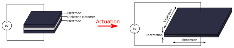
Dielectric elastomer actuators (DEAs) are a means to overcome the brittleness of piezoceramic devices. They replace the ceramic material with a softer type of transducer. DEA consists of a thin layer of elastomer, usually ranging from ten to two hundred microns in thickness, covered on both sides with flexible electrode coatings creating a variable capacitor. Once a voltage is applied across the DEA, a Maxwell stress is created, which causes the film to become compressed in the direction of thickness and expanded in area (Figure 2). The effective compressive stress is
where ε₀ is the permittivity of free space, εᵣ the relative dielectric constant, and E the applied electric field6. Since the stress increases with the square of the electrical field and since the electrical field strength is determined by the ratio of the applied voltage to the thickness of the film, thinner films achieve useful stresses at lower voltages — i.e., they provide an alternative method of reducing DEA operating voltages.
From a design perspective, this relationship indicates that there are three ways to increase the gain of DEAs: use an elastomer with large compliance, a high dielectric constant coating and a high breakdown field coating. The output energy density of a DEA scales as
where Y is the elastic modulus6. Since the energy density increases with the fourth power of the electrical field term, the electrical field term will dominate. Acrylic and silicone elastomers have been actuated to strain levels greater than 100 percent. In addition, the specific energy density of these materials is approximately one order of magnitude higher than that of single crystal PZT.
The first controlled DEA powered flight was successfully completed by Chen et al. Using multi-layered DEAs, they achieved a power density of 600 W/kg and a resonance frequency of 500 Hz per 100 mg actuator. These values represent the two major hurdles that prevented DEAs from being used in flight applications prior to this time: power density below 200 W/kg and bandwidth below 20 Hz. An example of a single-actuator based vehicle was able to accomplish only an open-loop lift off before tipping over. Closed loop hovering was accomplished with a 660 mg vehicle consisting of four individual modules, sustained for 16 seconds (Figure 3)12. The vehicles were also capable of operation following mid air collisions with walls and with each other12. There is a significant difference between the single module mass and the total mass of the assembled vehicle, since when referring to the mass of the flying vehicle, many times only the mass of a single module is referenced.
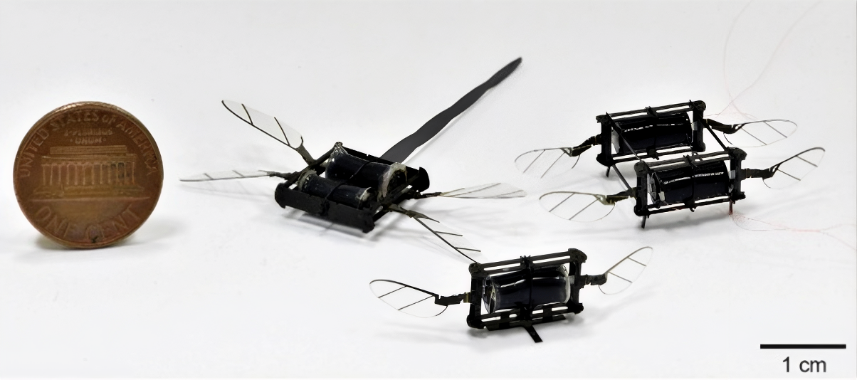
A subsequent 665 mg vehicle built upon the improvements made to the actuator itself6. The key innovation developed was that even though the quasi-static energy-density model describes the properties of DEAs well in terms of static performance, dynamic performance (i.e., resonant frequency, maximum output power, quality factor at resonance) determines the actual performance of DEAs in flight applications. Therefore, substituting Elastosil P7670 (elastic modulus 200 KPa vs. 140 KPa previously) resulted in a sharp peaked resonant frequency response curve. As a result, a 110 mg DEA was capable of achieving 1.2 kW/kg with 37% transduction efficiency at 475 Hz, representing a 100% increase in resonant frequency and a 560% increase in transduction efficiency compared to the previous generation’s DEAs6. The assembled vehicle demonstrated lift-to-weight ratios greater than 2.2:1, climb rates up to 70 cm/s, in-flight collision recovery capabilities, and was capable of executing a 360 degree somersault in less than 0.16 seconds — maneuvers that rigidly actuated sub-gram vehicles have not performed6.
DEAs also exhibit a disadvantage: nearly 2000 V as opposed to about 200 V required for piezoelectric devices, plus non-linear hysteresis behavior during operation that complicates control operations in closed-loop configurations. Therefore, choosing between DEA technology and piezoelectric technology represents a choice between different failure mechanisms rather than between good and bad options. Ren et al. addressed this issue directly via the creation of multi-layered DEAs utilizing optimized carbon nanotube electrodes for actuating forces as high as 0.36 N at displacements as high as 1.15 mm and frequencies as high as 400 Hz while maintaining an operational voltage of only 500 V for over two million cycles13. Four such modules were assembled into a 680 mg vehicle capable of hovering for 20 s with a maximum position error of 2.5 cm13. Additionally, a lift-to-weight ratio of 3.7 was measured for a single 167 mg module performing a static lift-off maneuver, and is not given here as the four-module flying vehicle’s ratio.
Magnetic actuation
Magnetic actuation creates motion in a magnetized object by utilizing an external magnetic field. Therefore, there is no propulsion energy required onboard. A body with a magnetic dipole moment (m) subjected to an external magnetic field (B), the fixed dipole model provides both the torque and the force as follows:
The torque arises from the magnetic dipole’s tendency to align with the external field, while the force arises from the gradient of the field rather than from a cross-product relationship. The force is the gradient of the magnetic potential energy. In a uniformly distributed magnetic field there will be no net force acting due to the absence of gradient, and therefore no net movement will occur unless a geometry is utilized to generate a gradient in the magnetic field for translational movement.
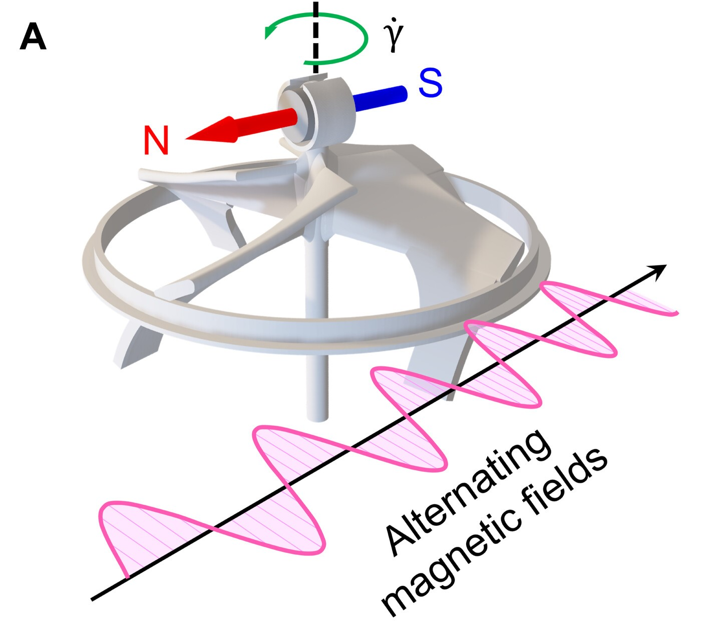
This concept has been used for flight applications and Sui et al. have successfully demonstrated a rotating wing flying robot weighing 21 mg with a 9.4 mm wingspan, powered by a single axis alternating magnetic field (Figure 4)7. The vehicle consists of a three-dimensional printed body comprising four propellers and a balance ring (14.7 mg) with two permanent magnets (3.15 mg each). The presence of the balance ring increases the rotational inertia of the system thus providing a gyroscopic stabilization mechanism for control of orientation. Hovering, collision avoidance and route adjustments were all demonstrated, with an estimated lift/drag ratio of 0.7 at a Reynolds number of approximately 25007. This represents currently the smallest and least massive vehicle capable of sustained flight without being physically tethered.
The distinction is important. As the vehicle contains no propulsion energy, the alternating magnetic field driving it is provided by separate external equipment, hence untethering the vehicle physically does not represent achieving energy independence. Thus, while the vehicle meets one criterion listed in Table 2, whether or not magnetic actuation can provide the ability to propel vehicles equipped with their own self contained energy source remains open.
Electrohydrodynamic thrust
The electro-hydro-dynamic (EHD) thrust process does not rely upon mechanical motion to produce propulsion. Instead, EHD uses electrical forces to create ions that travel to the collection plate and collide with surrounding particles (Figure 5)2. As these collisions occur, the surrounding air becomes displaced. This displacement of the air mass creates a pressure differential. It is the response to this pressure difference that creates the thrust. Plasma is formed using corona discharges due to avalanche ionization within the highly asymmetrical area between electrodes. However, corona discharge can be initiated without total dielectric breakdown of the medium2.
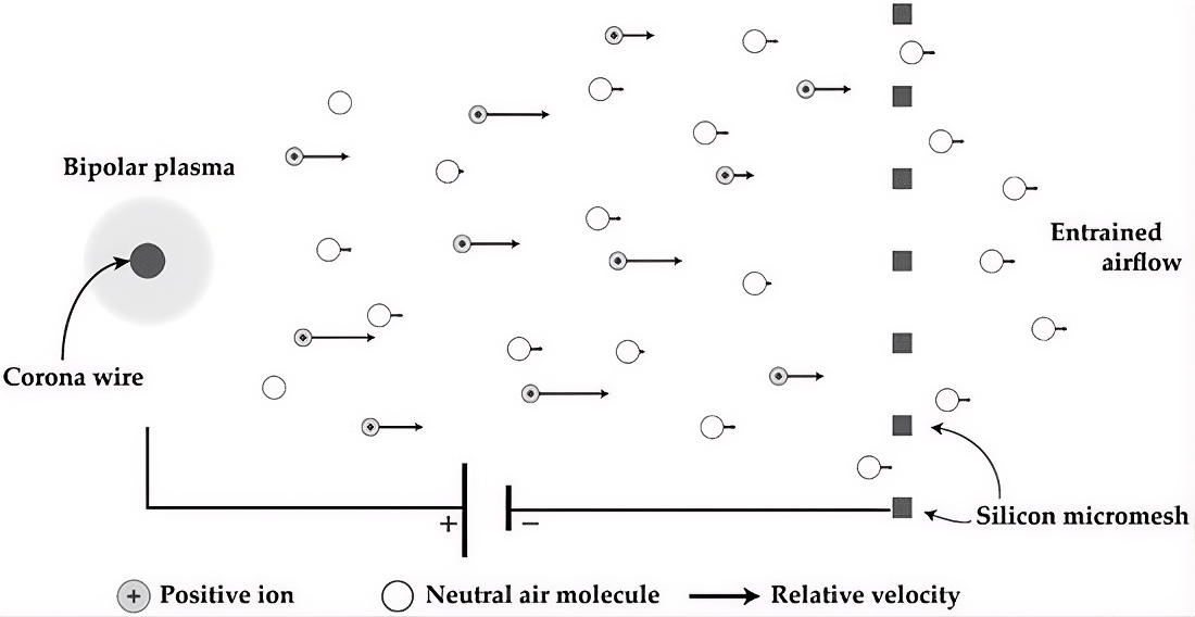
For an ideal one-dimensional model the force is
where I is ion current, d the drift distance, μ the ion mobility in air (about 2 × 10⁻⁴ m² V⁻¹ s⁻¹ for N₂⁺ in dry air), and β a loss factor covering indirect ion paths, the ratio of plasma-sheath size to drift gap, and collector drag2. Therefore, the amount of thrust generated increases when either the current supplied to the system increases or the distance traveled by ions (i.e., drift length) increases. Conversely, if ions are able to move more quickly they will transfer less momentum per unit charge and thus reduce the overall thrust. Since EHD relies solely upon electrostatic forces, the mechanism is scale-invariant. Therefore, as size decreases, both the required operational voltage and the thrust-to-weight ratio move in favorable directions2.
In fact, Drew et al. have demonstrated that this holds true. They designed an ionocraft (a 2 cm x 2 cm, 30 milligram vehicle having four 6 mm x 6 mm collector plates), which was capable of generating a thrust density greater than 7 N/m²2. By reducing the lithographically-defined emitter tip angle from 10 degrees to 5 degrees, they were also able to lower the corona onset voltage by about 100 volts2. The resulting vehicle was able to achieve an open-loop take-off with a 37 milligram nine axis IMU2, and track sinusoidal input commands up to 10 hertz2.
There is a structural control issue associated with this EHD configuration. Its coplanar thrusters do not produce yaw torque; therefore, the yaw component of the force-to-torque mapping is zero, the controllability matrix is rank-deficient, and the vehicle lacks yaw authority2. While sequential pitch-and-roll maneuvers would allow recovery of full rank controllability for example, or adding angled thrusters to provide additional directional capability, neither alternative has been implemented. In combination with the approximate 2000 volt operating requirement, this results in EHD being attractive primarily because of ease of construction and durability, but still far removed from autonomous controlled flight.
From the data presented in Table 1 comparing the four types of actuators discussed here, only piezo-electric and DEA based actuated vehicles have achieved controlled flight in a loop. The two remaining types of actuators (magnetic & EHD) have each had a single test platform fly. Neither of those platforms was capable of producing its own propulsive energy onboard: the magnetic platform depends on an externally generated field, and the EHD platform, while it generates thrust onboard, lacks yaw control authority. Piezoelectric-based actuators retain the advantage related to integration into a fully functional vehicle and have demonstrated sustained untethered flight with onboard power conversion, while magnetic actuation has also achieved untethered flight, powered by an externally generated field rather than onboard energy storage. DEA-based actuators lead in impact resistance and high-bandwidth maneuvering.
Fabrication
The primary challenges facing the development of flying micro robots include designing and building structures that span approximately 100 μm to 10 cm – a size scale that falls outside the capabilities of silicon MEMS and well beyond those of traditional machine tool-based machining. In addition, since force increases as length scales decrease, conventional bearings become less practical at smaller sizes, thus requiring new methods to be developed to articulate and connect moving parts, just as new actuators needed to be designed to create motion.
To address these needs Smart Composite Microstructures (SCMs) were created for the same size scale regime as microrobotic systems (as shown in Figure 6), and utilize a planar laminate configuration consisting of bulk laser-micromachined layers of different materials separated by adhesive film layers. SCMs have the ability to generate features down to 5 μm using laser micromachining, and also allow for any combination of materials in the layers of the laminate. High stiffness-to-weight carbon fibre reinforced composites are typically used in structural elements such as the beams or ribs, while very thin polyimide flexure hinges are often utilized to create revolute type joints that approximate frictionless bearings. These types of flexible laminate structures enable precision assembly through folding and have been successfully demonstrated in producing numerous, highly repeatable copies of all of the flight muscles, thorax, skeleton, and wings of the RoboBee5,23.
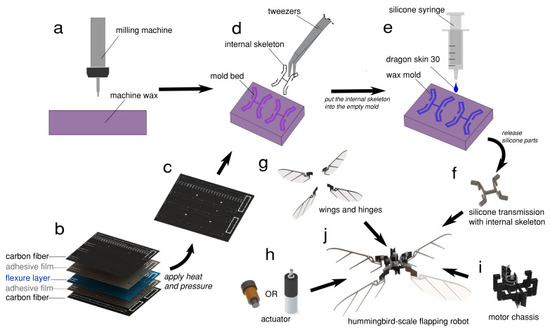
Smart Composite Microstructures provided the foundation for Printed Circuit MEMS (PC-MEMS), which extend the concept of planar laminates to three dimensionally shaped structures with embedded electric connections. Continuing along this line of research, Whitney et al.25 presented the concept of Pop-Up Book MEMS. With a single complex laminate containing one assembly degree of freedom in a similar fashion to a pop-up book, Pop-Up Book MEMS allows a three-dimensionally articulated structure to emerge. An array of machined layers is positioned on dowel pins, placed side by side and bonded in parallel. By applying anisotropic pre-strain during the bonding process, the pop-up process eliminates the need for much of the laborious, joint-by-joint assembly required by the original SCM process. Moreover, the pop-up process enabled the manufacture of five identical RoboBee bodies for the first successful controlled flight test5,25. Although conventional MEMS technologies will continue to be applicable for particular components, they do not meet many requirements for entire robotic systems. For example, Drew et al.2 manufactured the ionocraft electrodes on a SOI wafer with a device thickness of 40 μm using a single mask DRIE and vapor phase HFA etch release. The resulting electrodes contain lithographically defined asperities 500 μm long with 5 degrees tips that contribute to the 100 volt reduction in corona onset voltage discussed earlier. Dielectric standoff is provided by fused silica capillary columns, and the assemblies are accomplished using surface mount techniques under a dissection microscope using UV curable epoxy to join mechanically and Ag epoxy to join electrically2. While MEMS provides precise dimensions, it is relatively slow compared to hybrid laminate technologies and limits material choices and geometric complexity23; these limitations prompted the development of hybrid laminate technologies.
Lastly, soft actuators require yet another method. Chen et al. fabricated multilayer DEAs by spinning coating multiple layers of elastomer with electrode material deposited between each layer, followed by rolling the resultant sheet into cylindrical form6. However, elastomer selection directly effects fabrication time. For example, Elastosil P7670 takes about 5 minutes at 60°C to cure, whereas previously used materials took over 40 minutes at 70°C. Thus, fabrication time was reduced from about 6 hours for a 7-layered structure to under 2 hours for the same structure6. The remainder of the system follows SCM philosophy and converts linear motion generated by DEAs into wing stroke via a four bar linkage with compliant polyimide wing hinges that measure 2.05 mm x 0.1 mm x 12.7 μm. Additionally, the wings incorporate straightened carbon fiber internal spars for added collision resistance6.
What bounds this subsystem is not resolution, but reproducibility. Jafferis et al.18 determined that piezoelectric actuator lifetime is limited by micron-sized edge roughness left behind when laser cutting. Yields for complete vehicle assemblies remain low and lifetimes are measured in minutes rather than hours. Fabrication is the area without an identified emerging technology in the literature reviewed herein; instead, there is a significant open problem regarding transitioning current laminate technologies from experimental prototype level to repetitive production quality; essentially a manufacturing challenge versus a materials challenge.
Flight Control and Sensing
Stable flight at insect scale is qualitatively more difficult than at larger scales. Specifically, the rotational acceleration is inversely related to the characteristic length. Therefore, due to their small size, a vehicle at the insect scale will rotate away from the desired orientation much faster than a similar sized vehicle would at a larger scale8. In addition, the base line hovering kinematics for any body plan intended to mimic an insect are inherently dynamically unstable. This means that the controller needs to continually make corrective actions over a time frame that is an order of magnitude shorter than what a fighter aircraft needs8.
There are three components to the controller of the RoboBee. The first component of the controller involves determining the correct attitude based upon Lyapunov stability theory. There is both a proportional term that addresses the orientation error as well as a derivative term that provides damping to the rotations of the vehicle. Position in the lateral direction is determined by commanding the necessary body attitude to produce the desired angle of the thrust vector, as insects do. Finally, altitude is controlled using a linearized model about hover and does not need to be part of the same time-critical attitude loop, because the vehicle’s attitude can be assumed to remain approximately vertical near hover5. The total sensorimotor latency for the RoboBee controller was approximately 12 milliseconds compared to roughly 10 milliseconds for the neuromotor reflexes of Drosophila5. The flight test results indicated that the stabilizing torques were dependent largely on angular velocity measurements consistent with the role of halteres in Diptera flight.
Chen et al. developed a vehicle for demonstrating Dielectric Elastomer Actuator (DEA) technology and utilized a Vicon motion-tracking system for state estimation. The system included a linear voltage-to-force mapping for hovering and individual take-off voltages for each of the four modules of the vehicle. When performing somersault maneuvers, the vehicles required a quadratic force-to-voltage mapping due to the fact that the commanded lift varied from zero to two times the weight of the vehicle during both the acceleration phase and deceleration phase of the maneuver. Maneuver sequence includes five phases: take-off, ascend, flip, recover, hover — and takes 0.16 seconds to complete a 360 degree rotation6. Using a Simulink model, Drew et al. modeled the performance characteristics of the ionocraft including measured actuator dynamics, aerodynamic drag and sensor noise. Three PID loops provide stable hovering and square trajectories with outputs mapped to four thrusters — however, yaw authority remained unresolved2.
Onboard sensing has progressed one modality at a time. Each demonstration utilizes a vehicle of the RoboBee type instead of developing a different airframe. Fuller et al. added a commercially available MEMS gyro weighing 40 milligrams to an 80 milligram vehicle8. Although body accelerations reached 5 g at the sensor location, the gyro provided clean angular-rate data and permitted 2–5 s hovering flights in which position information was provided solely by motion capture. The authors stated that accelerometer readings were severely contaminated by flapping-induced vibrations while gyro readings were unaffected8 — thus limiting the choice of sensors for any future autonomous platform. Helbling et al. demonstrated that an analog anisotropic-magnetoresistive magnetometer provided accurate absolute-angle feedback regardless of proximity to the actuators9. This works because piezoelectric drive uses high voltage but very low current, and so produces minimal local magnetic fields. The result permitted pitch maneuvers in under 200 ms, and the first absolute yaw control at this scale, achieved through feedback on split-cycle drive signals9.
For altitude, Duhamel et al. designed a 33 milligram one-dimensional optical flow sensor and incorporated it into a 68 milligram vehicle resulting in a 101 milligram system capable of achieving the first controlled vertical flight utilizing onboard rather than external altitude feedback10 — and an infrared time-of-flight proximity sensor has also been successfully operated in closed-loop26. Fuller et al. operated an ocelli-inspired sensor — three light sensors mimicking those found in simple eyes of insects — providing attitude feedback based on the angular velocity of a light source on a 106 milligram vehicle, representing the first biomimetic onboard sensor capable of stabilizing free flight at fly scale11.
These accomplishments establish two limitations. First, these modalities have never been combined: although each modality exists as separate elements with each element previously tested separately, no vehicle has ever had more than one modality operating simultaneously. Second, all demonstrations have relied on external tracking. The RoboBee relies on an array of infrared cameras for position and orientation estimation at 500 Hz from retroreflective markers5; the DEA vehicles utilize six Vicon cameras operating at 500 Hz within a 40 x 40 x 20 cm space, tracking is lost >100° in either pitch or roll restricting somersault testing6; the ionocraft transmitted IMU data at approximately 100 Hz during open-loop takeoff and displayed erratic transient behavior during high voltage application, indicating a need for improved electromagnetic shielding2. All demonstrations shown in Table 2 rely on external tracking for stability.
The third limitation becomes apparent only upon comparison of platforms listed in Table 1. Yaw is consistently the most difficult axis to control: ionocraft cannot provide yaw control whatsoever as ion thrust produces no angular momentum; original RoboBee provides control only to its rate rather than its absolute heading5; DEA vehicle at 665 milligrams deliberately excludes yaw authority as its linearly acting module cannot produce sufficient control torque6; dedicated onboard yaw control was first implemented only by Helbling et al.’s magnetometer study restricted to wires; four-wing platform’s steering demonstration represents the first demonstration of yaw-steering actuation at this scale. Only the X-Wing platform, with four independent wings, provides full pitch, roll, and yaw torque authority, suggesting that yaw control at this scale is less a sensing issue than an actuator topology issue. Autonomous navigation is another issue beyond stabilization, requiring planning and perception without global positioning knowledge — qualitatively harder at this scale than for larger platforms that can afford cameras, computing resources and communication equipment for simultaneous localization and mapping.
Reinforcement learning policies have generated rapid escape maneuvers, body flips and flight in wind on flapping platforms in the 10–30g range27,28. At sub-gram scales no such demonstrations exist. Processor mass, memory, inference latency, communication requirements and electrical power requirements to operate a learned policy onboard a 100-300mg vehicle have not been identified and therefore should not be interpreted as relevant to this scale from previous work at much higher masses.
Power and Energy
The power supply is probably the biggest constraint on achieving autonomy at this scale. Karpelson et al. formalized the problem of designing autonomous hovercraft by categorizing the components of the airframe into two types: those that produce lift (the energy source, power electronics, actuator, transmission, and wings) and those that consume lift (the airframe, sensors, control electronics). They then derived the range of masses and flapping frequencies at which a vehicle could achieve autonomous hovering. Energy storage density and power electronics efficiency were found to be the two variables with the largest impact on flight duration29.
All controlled flight demonstrations to date have been tethered. The tether used to connect the RoboBee is made of 51 gauge copper wire that is bundled together in groups of 4, weighing approximately 5 mg and carries both power and command signals. It is designed to be light and flexible so as to have minimal effect on flight dynamics. Additionally, the piezoelectric actuators operate with a 150–200 V drive signal supplied by an external power source. All of the DEA vehicles and the ionocraft are also tethered6,12. Although tethering provides some degree of passive stability during open loop flight, it severely limits the number of degrees of freedom available to the vehicle. At these masses, the spring tension generated by the tether will often overpower the vehicle.
Converting a low voltage input to the high voltage output required for actuator operation is a significant design challenge. Karpelson et al. evaluated three different topologies for creating low mass piezoelectric drive systems: tapped-inductor boost converters, bidirectional flyback converters, and charge pump ladders. They also provided several techniques for implementing very low mass custom magnetics as well as very low power control circuits17. Lower layer thicknesses in multilayer actuators reduce the required drive voltage allowing for less complex and lighter weight boost stages. Also, using a simultaneous drive configuration allows a high voltage bias to be applied across multiple actuators reducing the number of independent drive stages needed. Techniques such as dynamic common mode adjustments, envelope tracking, and charge sharing have resulted in a roughly 30–47% reduction in power consumption and a roughly 37% reduction in mass relative to their discrete counterparts17. Integrating drive stage and control logic onto a single chip is expected to result in power-electronics mass being less than the 40 mg contained by the X-Wing.
One example of an untethered flight demonstrated at this scale is instructional as a working example of how each component constrains others. Jafferis et al.’s RoboBee X-Wing is a 90 mg vehicle that consists of four wings driven by two alumina reinforced piezoelectric bimorph actuators3. The four-wing configuration has improved aerodynamic efficiency up to 29% when compared to similar two-wing configurations, and achieves a maximum lift to weight ratio of 4.1:13. The thrust efficiencies are also similar to those achieved by similarly sized insects such as bees. The design chain flows in one direction. Four wings reduce the amount of power required to generate lift; lower amounts of power allow for smaller and lighter power electronics; a bidirectional flyback converter was chosen based on lowest part count and mass to convert a 4.8 V photovoltaic source to the roughly 200 V, 170 Hz drive signal necessary for driving; alternatingly powering either only the positive or negative bimorph plates reduced actuator stresses while reducing the number of control signals necessary; and the lower power requirements allowed for a smaller solar array which brought the required level of illumination within reach. The entire integrated system weighed a total of 259 mg, measured 3.5 cm along the wing tips, stood 6.5 cm tall and consumed 110-120 mW3.
This mass budget explains why chemical storage was abandoned as an option. For instance, a commercially available lithium-ion cell at a rate of roughly 1.2 W/g would need to weigh over four times the weight of the vehicle to meet its needs, which is clearly not feasible within a system that weighs only 259 mg3. However, photovoltaics at roughly 2.3 W/g under three-sun illumination do meet the budget, although three suns is far greater than typical levels of sunlight, thus this represents a laboratory solution rather than an approach toward developing outdoors autonomy. This underlying difficulty is recursive: as battery size decreases, packaging and sealing become major contributors to mass due to their high surface area to volume ratios and therefore energy density is lost precisely when it is most needed; simultaneously flapping motion requires tens of milliwatts per gram at high voltages requiring additional power electronics mass6,17. Increasing energy capacity increases vehicle mass increasing lift and power requirements increasing energy capacity further. Wood estimated that a tethered lift off vehicle equipped with onboard lithium polymer batteries would provide sufficient energy for a 5-10 minute flight16; however, no demonstrable examples have produced even a small fraction of that length of un-tethered flight.
Integration: Why the Subsystems Cannot Be Solved Separately
Each of the four systems shown above terminates at a boundary that is outside of that system. Each additional element — sensors, power electronic boards, energy sources — will consume payload capability and there are limited options to choose from. The average thrust required by a hovering flight vehicle is generally as much as one gram of thrust per gram of body mass (T = m x g). Therefore, the increased demand for thrust due to added mass increases linearly with mass. However, the mechanical power required to generate this thrust does not increase linearly with mass. Mechanical power also depends upon wing load, flapping frequency and wing geometry. As such, even small amounts of payload can cause disproportionately large increases in actuator output requirements, which in turn require larger power systems.
The Four Wing Platform provided a direct measure of these limitations. A 143 mg air frame was capable of carrying payloads up to 260 mg4. This amount would allow for either a complete set of sensors (e.g., IMU, Magnetometer, Height Sensor), or a complete set of power components (Battery, Boost Converter), but not both. By utilizing four wings instead of two, Fuller improved the aerodynamic efficiency of the platform enough to widen that payload margin — exactly the type of cross-system trade-off that the community has been forced to make4.
Of the platforms that have been reviewed in this paper, the X-Wing has the greatest number of systems integrated into it3. Integration carries a size cost as well as a mass one: the X-Wing’s photovoltaic array adds height rather than payload mass, bringing the assembled vehicle to 6.5 cm tall, well beyond the footprint of the four-wing airframe alone3. It is the X-Wing that represents an important step in the causal chain described previously. The failure over the past decade to optimize separate systems (actuation performance on a two-wing platform or battery capacity without optimizing the actuation efficiency) demonstrates that at insect scales integration is the fundamental problem rather than simply an after-the-fact engineering issue3.
There currently exist no fully autonomous vehicles. To date, no vehicle has successfully carried high density energy storage devices, high voltage drive electronics, a complete sensor suite and sufficient onboard computing resources to implement closed-loop control while operating at less than 1 gram. The difference in capabilities between current vehicles and those desired is demonstrated clearly in Table 2. There are no vehicles listed that utilize onboard state estimation, nor are any vehicles that operate autonomously. Similarly, each vehicle scored fewer than three of the five criteria.
Conclusion
The development of flying micro-robots has undergone rapid growth since the early 2000s, beginning as concepts and progressing to prototype systems that include take-off, hovering, maneuverability and recently, untethered flight. That process was tracked throughout this review via four interrelated sub-systems.
In terms of actuation, piezoelectric bimorphs set the energy-density standard, provided the first tethered takeoff and the first controlled flight of an insect-scale robot1,16,5. Subsequently, dielectric elastomer (DEA), magnetic and electro-hydro-dynamic (EHD) actuators expanded upon what was available in the baseline of piezoelectric bimorphs — namely, collision resiliency and high bandwidth maneuvers in the case of DEA6,12, extremely small sizes in the case of magnetic actuators7, and propulsive force generation with no moving parts in the case of EHD2. In terms of fabrication, smart composite microstructures and MEMS based pop-up books resolved the issues associated with building articulated structures greater than MEMS allows and less than machining tolerances permit23,25. In terms of control systems, the field has evolved from completely external sensing methods to include onboard sensing systems — namely MEMS gyroscopes8, magnetometers9, optical flow sensors10, and ocelli inspired vision11 — although none have yet been flown collectively. Finally, in terms of power sources, systematic energetic analysis defined the design space29, high-voltage drive electronics were reduced to a milligram-scale footprint17, and four wing aerodynamics combined with alumina reinforced actuators and beamed solar power generated the first prolonged untethered flight of an insect size vehicle3.
It should be noted that none of these advancements alone are sufficient to allow autonomous flight. There are several areas that currently represent significant barriers. Energy storage is perhaps the most obvious barrier. Chemical batteries currently represent the primary means of storing energy for flight vehicles. However, they weigh significantly more than the vehicle can carry at this scale. As such, flight times are typically limited to minutes or less, and there appears to be very little potential for improving battery energy density further at these sizes16,3. The second major barrier is onboard state estimation. Virtually all closed loop flights currently require some form of external motion capture system operating at 500 Hz or faster5,6,2. Although there exist onboard sensor systems that could potentially replace the need for these external systems, none have been successfully integrated onto a single vehicle. The third major barrier is low fabrication yield and short operational lifetime. Current yields for entire vehicles remain relatively low while operational lifetimes remain measured in minutes18. Consequently, experimental iterations can only be performed for relatively short periods of time.
All three major barriers are coupled to one common underlying issue — the relationship between piezoelectric brittleness and DEA drive voltage. These two seemingly disparate limitations represent opposing sides of a trade-off where each design decision represents either a reduction in one limitation versus an increase in another19,6.
There exists recent evidence that suggests that the field of flying micro robots may be nearing a transition. The work completed by Ren et al. described a low voltage long endurance DEA that demonstrated soft actuators can match rigid actuators on the integrated performance metrics that dictate if power electronic circuits can be supported13. Also, Fuller’s four wing platform demonstrated that improvements in aerodynamic efficiency can be translated directly into additional payload margin for sensors and power4. The X-Wing demonstrated that simultaneous co-optimization across subsystems can break circular design constraints that have thwarted decades of optimizing individual subsystems3. It remains to be seen if learning based control can make contributions to the advancement of flying micro robots; currently it has only been demonstrated at an order of magnitude higher than this mass class 27,28. Swarm methodologies also remain conceptual at insect scales30.
In summary, the current state is a set of individually matured subsystems: actuators capable of producing insect-level power densities, fabrication techniques able to produce articulated assemblies repeatedly, onboard sensors capable of detecting all required modalities, and one vehicle capable of untethered flight. The major challenges are energy storage sufficiently lightweight to carry onboard, onboard state estimation independent of external motion capture systems, and fabrication yields adequate to support iterative experimentation. The key future directions are low voltage soft actuators, increased aerodynamic efficiencies translated into additional payload margins for sensors and power, and above all the simultaneous co-optimization of these subsystems rather than their independent optimization.
References
- R. J. Wood, “The first takeoff of a biologically inspired at-scale robotic insect,” IEEE Trans. Robot., vol. 24, no. 2, pp. 341–347, Apr. 2008 [↩] [↩] [↩] [↩] [↩] [↩] [↩]
- D. S. Drew, N. O. Lambert, C. B. Schindler, and K. S. J. Pister, “Toward controlled flight of the ionocraft: a flying microrobot using electrohydrodynamic thrust with onboard sensing and no moving parts,” IEEE Robot. Autom. Lett., vol. 3, no. 4, pp. 2807–2813, Oct. 2018 [↩] [↩] [↩] [↩] [↩] [↩] [↩] [↩] [↩] [↩] [↩] [↩] [↩] [↩] [↩] [↩] [↩] [↩] [↩]
- N. T. Jafferis, E. F. Helbling, M. Karpelson, and R. J. Wood, “Untethered flight of an insect-sized flapping-wing microscale aerial vehicle,” Nature, vol. 570, no. 7762, pp. 491–495, 2019 [↩] [↩] [↩] [↩] [↩] [↩] [↩] [↩] [↩] [↩] [↩] [↩] [↩]
- S. B. Fuller, “Four wings: an insect-sized aerial robot with steering ability and payload capacity for autonomy,” IEEE Robot. Autom. Lett., vol. 4, no. 2, pp. 570–577, Apr. 2019 [↩] [↩] [↩] [↩] [↩] [↩]
- K. Y. Ma, P. Chirarattananon, S. B. Fuller, and R. J. Wood, “Controlled flight of a biologically inspired, insect-scale robot,” Science, vol. 340, no. 6132, pp. 603–607, May 2013 [↩] [↩] [↩] [↩] [↩] [↩] [↩] [↩] [↩] [↩] [↩] [↩] [↩]
- Y. Chen, S. Xu, Z. Ren, and P. Chirarattananon, “Collision resilient insect-scale soft-actuated aerial robots with high agility,” IEEE Trans. Robot., vol. 37, no. 5, pp. 1752–1764, 2021 [↩] [↩] [↩] [↩] [↩] [↩] [↩] [↩] [↩] [↩] [↩] [↩] [↩] [↩] [↩] [↩] [↩] [↩] [↩] [↩] [↩]
- F. Sui, W. Yue, K. Behrouzi, Y. Gao, M. Mueller, and L. Lin, “Untethered subcentimeter flying robots,” Sci. Adv., vol. 11, no. 13, eads6858, Mar. 2025 [↩] [↩] [↩] [↩] [↩] [↩]
- S. B. Fuller, E. F. Helbling, P. Chirarattananon, and R. J. Wood, “Using a MEMS gyroscope to stabilize the attitude of a fly-sized hovering robot,” in Proc. Int. Conf. Micro Air Veh. (IMAV), 2014 [↩] [↩] [↩] [↩] [↩] [↩] [↩]
- E. F. Helbling, S. B. Fuller, and R. J. Wood, “Pitch and yaw control of a robotic insect using an onboard magnetometer,” in Proc. IEEE Int. Conf. Robot. Autom., 2014, pp. 5516–5522 [↩] [↩] [↩] [↩] [↩]
- P.-E. J. Duhamel, N. O. Pérez-Arancibia, G. L. Barrows, and R. J. Wood, “Biologically inspired optical-flow sensing for altitude control of flapping-wing microrobots,” IEEE/ASME Trans. Mechatronics, vol. 18, no. 2, pp. 556–568, Apr. 2013 [↩] [↩] [↩] [↩]
- S. B. Fuller, M. Karpelson, A. Censi, K. Y. Ma, and R. J. Wood, “Controlling free flight of a robotic fly using an onboard vision sensor inspired by insect ocelli,” J. R. Soc. Interface, vol. 11, no. 97, 20140281, Aug. 2014 [↩] [↩] [↩] [↩]
- Y. Chen, H. Zhao, J. Mao, P. Chirarattananon, E. F. Helbling, N.-S. P. Hyun, D. R. Clarke, and R. J. Wood, “Controlled flight of a microrobot powered by soft artificial muscles,” Nature, vol. 575, no. 7782, pp. 324–329, 2019 [↩] [↩] [↩] [↩] [↩] [↩]
- Z. Ren, S. Kim, X. Ji, W. Zhu, F. Niroui, J. Kong, and Y. Chen, “A high-lift micro-aerial-robot powered by low-voltage and long-endurance dielectric elastomer actuators,” Adv. Mater., vol. 34, e2106757, 2022 [↩] [↩] [↩] [↩] [↩]
- J. G. Smits, S. I. Dalke, and T. K. Cooney, “The constituent equations of piezoelectric bimorphs,” Sens. Actuators A, vol. 28, no. 1, pp. 41–61, 1991 [↩] [↩]
- M. R. A. Nabawy and W. J. Crowther, “Dynamic electromechanical coupling of piezoelectric bending actuators,” Micromachines, vol. 7, no. 1, art. no. 12, 2016, doi: 10.3390/mi7010012 [↩]
- R. J. Wood, E. Steltz, and R. S. Fearing, “Optimal energy density piezoelectric bending actuators,” Sens. Actuators A, vol. 119, no. 2, pp. 476–488, 2005 [↩] [↩] [↩] [↩]
- M. Karpelson, G.-Y. Wei, and R. J. Wood, “Driving high voltage piezoelectric actuators in microrobotic applications,” Sens. Actuators A, vol. 176, pp. 78–89, 2012 [↩] [↩] [↩] [↩] [↩]
- N. T. Jafferis, M. Lok, N. Winey, G.-Y. Wei, and R. J. Wood, “Multilayer laminated piezoelectric bending actuators: design and manufacturing for optimum power density and efficiency,” Smart Mater. Struct., vol. 25, no. 5, 055033, 2016 [↩] [↩] [↩] [↩] [↩] [↩] [↩]
- N. T. Jafferis, M. J. Smith, and R. J. Wood, “Design and manufacturing rules for maximizing the performance of polycrystalline piezoelectric bending actuators,” Smart Mater. Struct., vol. 24, no. 6, 065023, 2015 [↩] [↩] [↩]
- Z. Ma and D. Sameoto, “A review of electrically driven soft actuators for soft robotics,” Micromachines, vol. 13, no. 11, art. no. 1881, 2022, doi: 10.3390/mi13111881 [↩]
- Y. Chen, C. Arase, Z. Ren, and P. Chirarattananon, “Design, characterization, and liftoff of an insect-scale soft robotic dragonfly powered by dielectric elastomer actuators,” Micromachines, vol. 13, no. 7, art. no. 1136, 2022, doi: 10.3390/mi13071136 [↩]
- D. S. Drew and K. S. J. Pister, “Geometric optimization of microfabricated silicon electrodes for corona discharge-based electrohydrodynamic thrusters,” Micromachines, vol. 8, no. 5, art. no. 141, 2017, doi: 10.3390/mi8050141 [↩]
- R. J. Wood, S. Avadhanula, R. Sahai, E. Steltz, and R. S. Fearing, “Microrobot design using fiber reinforced composites,” J. Mech. Des., vol. 130, no. 5, 052304, May 2008 [↩] [↩] [↩]
- H. Gao, J. Lynch, and N. Gravish, “Soft molds with micro-machined internal skeletons improve robustness of flapping-wing robots,” Micromachines, vol. 13, no. 9, art. no. 1489, 2022, doi: 10.3390/mi13091489 [↩]
- J. P. Whitney, P. S. Sreetharan, K. Y. Ma, and R. J. Wood, “Pop-up book MEMS,” J. Micromech. Microeng., vol. 21, no. 11, 115021, 2011 [↩] [↩] [↩]
- E. F. Helbling, S. B. Fuller, and R. J. Wood, “Altitude estimation and control of an insect-scale robot with an onboard proximity sensor,” in Proc. Int. Symp. Robot. Res. (ISRR), Springer Proc. Adv. Robot., vol. 2, pp. 57–69, 2018 [↩]
- Z. Tu, F. Fei, and X. Deng, “Bio-inspired rapid escape and tight body flip on an at-scale flapping-wing hummingbird robot via reinforcement learning,” IEEE Trans. Robot., vol. 37, no. 5, pp. 1742–1751, 2021 [↩] [↩]
- T. Kim, I. Hong, S. Im, S. Rho, M. Kim, Y. Roh, C. Kim, J. Park, D. Lim, D. Lee, S. Lee, J. Lee, I. Back, J. Cho, M. R. Hong, S. Kang, J. Lee, S. Seo, U. Kim, Y.-M. Choi, J.-S. Koh, S. Han, and D. Kang, “Wing-strain-based flight control of flapping-wing drones through reinforcement learning,” Nat. Mach. Intell., vol. 6, pp. 992–1005, 2024, doi: 10.1038/s42256-024-00893-9 [↩] [↩]
- M. Karpelson, J. P. Whitney, G.-Y. Wei, and R. J. Wood, “Energetics of flapping-wing robotic insects: towards autonomous hovering flight,” in Proc. IEEE/RSJ Int. Conf. Intell. Robots Syst. (IROS), 2010 [↩] [↩]
- M. Dorigo, G. Theraulaz, and V. Trianni, “Reflections on the future of swarm robotics,” Sci. Robot., vol. 5, no. 49, eabe4385, 2020 [↩]