
Abstract
The rapid electrification of commercial urban logistics necessitates a transition from traditional internal combustion engine (ICE) chassis architectures to platforms optimized for high-density battery arrays and variable payload requirements. Many current electric delivery vehicles rely on modified ladder-frame structures originally designed for ICE vehicles, which may not be optimised for the dynamic and asymmetric loading conditions typical of modern delivery operations. This research investigates the hypothesis that a lightweight triangulated semi-spaceframe chassis architecture can improve structural efficiency and load distribution compared with conventional ladder-frame designs. Using computer-aided design modelling and finite element analysis, ladder-frame and triangulated semi-spaceframe chassis configurations are comparatively evaluated under simulated loading scenarios representing cargo distributions from 0% to 100% payload capacity. Structural performance is assessed using torsional loading and asymmetric load cases representative of uneven cargo placement and road-induced forces, with performance metrics including torsional stiffness, displacement, and maximum von Mises stress. The optimised semi-spaceframe increased torsional stiffness by a factor of 53.7 (2129 vs 39.6 Nm/deg) relative to the ladder-frame baseline, with an 11.4× gain in specific stiffness despite a 4.71× higher mass, and it reduced vertical sag by 23 to 29 times under 800 kg asymmetric and symmetric payloads while remaining within the elastic limit where the baseline yielded. These results indicate that triangulated members redirect loads through axial paths rather than bending-dominated rails, so that geometric triangulation rather than added material is the primary driver of the improvement. These findings contribute to the development of lightweight, structurally optimised electric vehicle chassis architectures capable of maintaining durability and stability under variable payload conditions in commercial delivery applications.
Keywords: Electric Vehicles, Finite Element Analysis, Spaceframe, Structural Optimization
Introduction
Current State of Urban Logistics
The accelerating electrification of urban logistics1 has introduced a class of structural engineering challenges that existing vehicle chassis platforms struggle to address. Inadequate torsional stiffness under variable payload directly compromises suspension geometry stability. With 1.19 million annual road traffic fatalities2, the structural integrity of electric delivery vehicles (EDVs) operating under variable payload conditions represents a safety imperative and an engineering gap that has received insufficient investigation.
Many modern electric delivery vehicle platforms inherit modified ladder-frame chassis architectures originally developed for internal combustion engine (ICE) vehicles3. These frames consist of two longitudinal rails connected by transverse crossmembers. Whilst these frames were designed to transmit powertrain torque and accommodate the concentrated mass of an engine-transmission assembly positioned ahead of the axle centreline4, the mass distribution, torsional loading environment, and load path geometry of battery-electric drivetrains differ fundamentally from these design assumptions. In electric delivery vehicles, the powertrain mass is distributed along the floor via a battery pack and payload conditions vary continuously between near-empty and full capacity across stop-start urban routes5. Therefore, adapting ICE ladder-frame architectures to this new loading environment produces structures that are simultaneously over-mass in unnecessary regions and under-stiff where torsional and asymmetric load resistance is most critical6.
Triangulated semi-spaceframe architectures offer a fundamentally different structural strategy. By subdividing a structure into triangular units, semi-spaceframes convert external loads into axial tension and compression within individual members, distributing load uniformly across the entire cross-section of each element and eliminating the inefficiency of bending-dominated stress7. These properties have been exploited extensively in motorsport and aerospace applications, but their systematic application to electric delivery vehicle platforms remains an underexplored area of structural engineering research.
This paper investigates the hypothesis that a lightweight triangulated semi-spaceframe chassis architecture produces measurably superior structural efficiency compared with a conventional ladder-frame baseline under torsional, asymmetric, and symmetric payload loading conditions representative of urban electric delivery operations. This will be quantified using the comparative evaluation metrics of torsional stiffness, specific stiffness, vertical deflection, and von Mises stress distribution. The study employs CAD modelling and FEA simulation within Autodesk Fusion 360, with solid-proxy geometry corrected by mathematically derived factors to reflect the physical behaviour of hollow tubular steel construction. The iterative design evolution from baseline ladder frame to optimised semi-spaceframe is documented to provide reproducible engineering justification for each architectural modification.
The contribution of this work is threefold: it applies and documents an iterative FEA-guided chassis optimisation methodology tailored to variable payload electric delivery vehicles; it demonstrates that geometric triangulation, rather than increased material mass, is the primary driver of structural performance improvement; and it proposes the semi-spaceframe architecture as a promising, modular structural platform for next-generation lightweight electric delivery vehicles.
Electric Vehicle Chassis Architectures & Theory
The chassis of a vehicle is its primary load-bearing structure responsible for carrying static payload, transmitting dynamic road-induced forces through the suspension, resisting torsional distortion under asymmetric loading, and providing a stable platform for body and drivetrain components8. Commercial vehicles often use the ladder-frame design as its two parallel longitudinal rails efficiently support a heavy engine-transmission assembly at the front while allowing a flat cargo bay at the rear9.
The transition to battery-electric drivetrains fundamentally alters these constraints. Electric motors are axle-mounted while battery packs are distributed across the floor, producing a low, even mass distribution4. Hence, many manufacturers have developed skateboard platforms, or flat battery-housing structures that use the housing itself to increase structural stiffness10. However, in the commercial delivery sector, the economic pressure from the rapid growth of emerging markets has led to a prevalence of adapted ICE platforms over purpose-built electric architectures11.
These adapted chassis must be heavily reinforced to manage the differing mass distribution and torsional loads of battery-electric powertrains, leading to significant inefficiencies and motivating investigation into alternative chassis architectures.
A ladder frame relies on bending resistance in the longitudinal rails with transverse crossmembers providing limited torsional coupling between rails. The lack of diagonal members means that the frame is susceptible to in-plane shear deformation and geometric instability where the rectangular bays deform into parallelograms when forces are applied7. This weakness against shear deformation is a fundamental geometric limitation that cannot be fully corrected by increasing thickness or changing material without disproportionate mass penalties.
A semi-spaceframe is a three-dimensional truss-like structure with members arranged such that loads are transmitted mainly as axial forces of tension or compression along the member axis rather than bending moments7. Triangulation also increases resistance to shear deformation. This geometric advantage motivated the progressive introduction of triangulated members in this study. Unlike a full spaceframe used in Formula motorsport, a semi-spaceframe applies triangulation and closed-loop principles selectively to the primary structural regions, helping reduce weight and retaining practical accessibility for manufacturing.
Structural Theory
A load path is the route through which an applied force is transmitted from its point of application8. In a vehicle chassis, all external forces enter the structure at the suspension nodes, with the goal of the chassis being to transmit these forces across the structure without exceeding material stress limits at any intermediate point. Therefore, the efficiency of the chassis is not just dependent on the strength of each member, but how well the structural geometry directs forces along direct, short load paths that avoid stress concentration and bending amplification in members4.
In a ladder frame, the load path is essentially two-dimensional: a force applied at a suspension node travels along the nearest longitudinal rail. Because this unsupported span is long before reaching the adjacent crossmember, the side rail experiences substantial bending, with bending moment increasing with span length under point loading7,12.
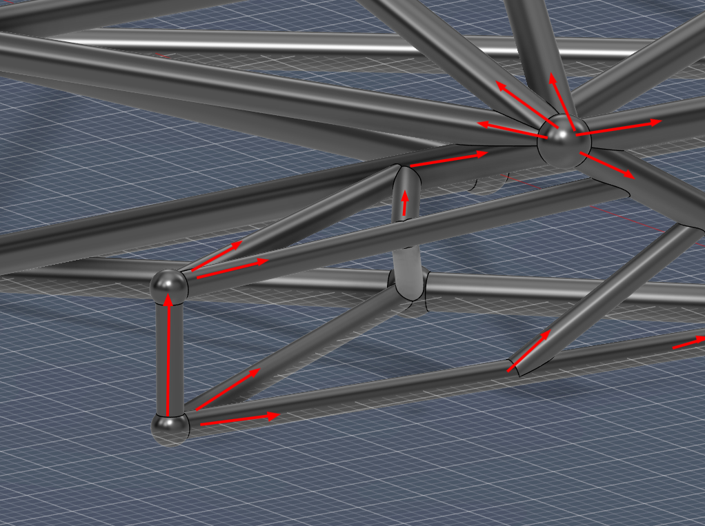
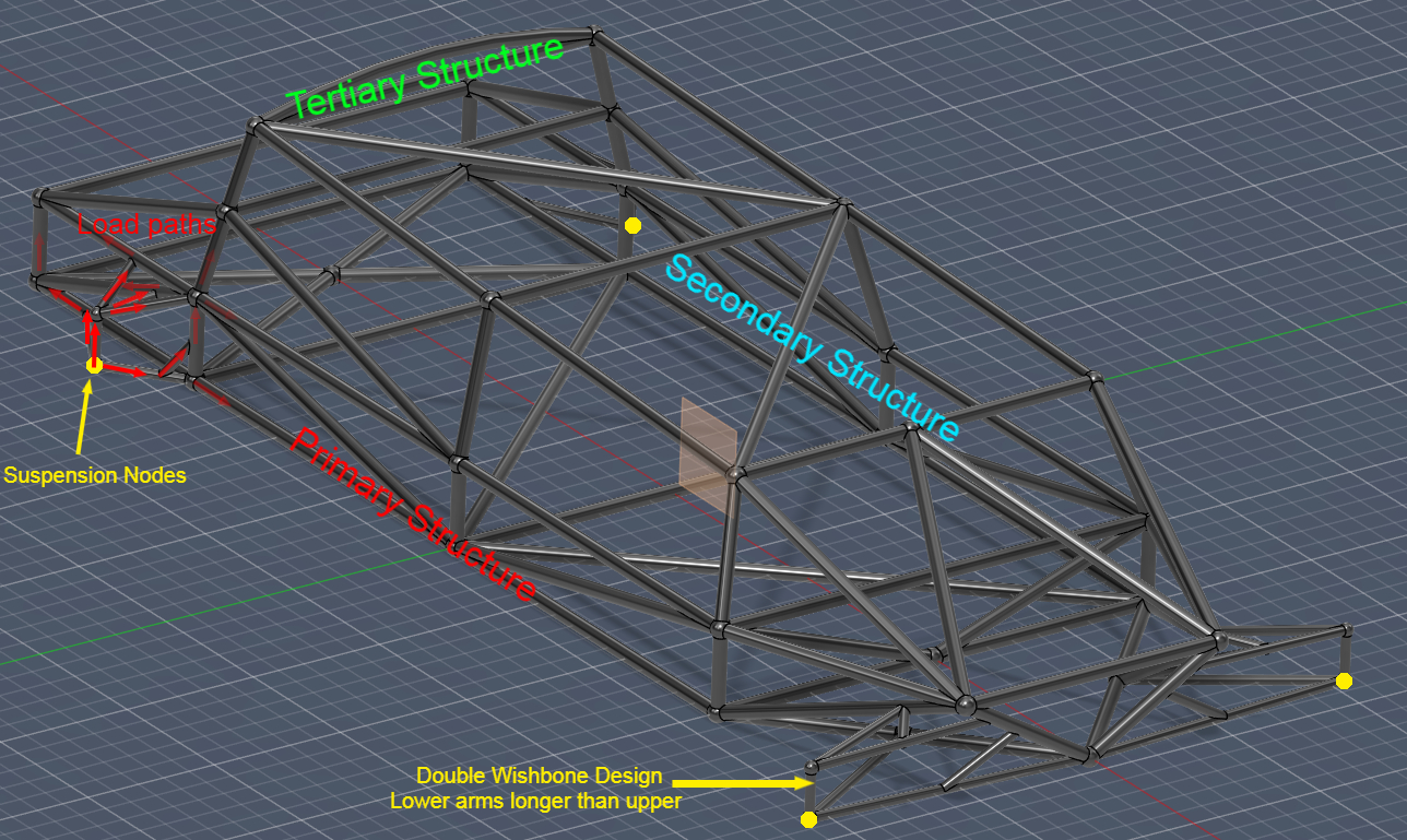
In the proposed semi-spaceframe design, suspension pickup points were treated as primary structural nodes from which diagonal members route loads into adjacent triangulated regions, distributing force across multiple members simultaneously, as in Fig. 1.
Structural efficiency depends on whether loads are carried primarily through bending or axial force transfer. Under bending, the stress distribution across a cross-section is linear:
where M is the local bending moment, y is the distance from the neutral axis, and I is the second moment of area. Only the extreme fibres (maximum y) approach the material’s yield strength.
Under axial loading, the stress is uniform across the entire cross-section:
where P is the applied axial force and A is the cross-sectional area. Every fibre of the material is engaged to the same stress level, representing 100% material utilisation across the section.
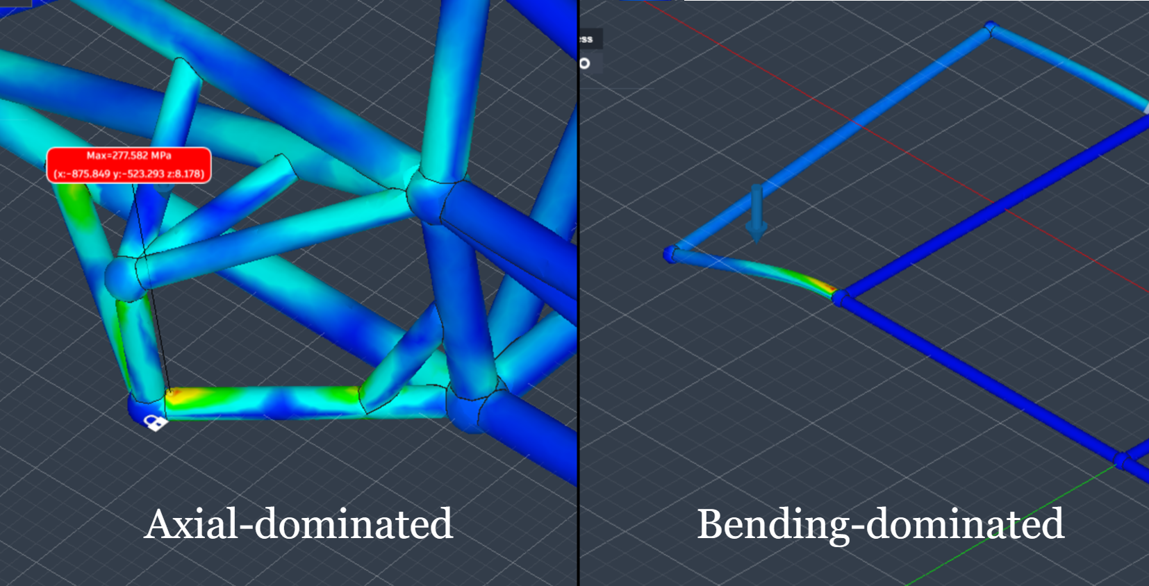
This mechanism increases the effective load capacity of each member before yield onset, addressing the bending-dominant failure mode of ladder-frame rails: the triangulated geometry redirects these loads into axial tension and compression paths, engaging the full cross-section of each member and raising the effective load capacity before yield, as in Fig. 2.
Torsional stiffness K is the ratio of applied torque T to the resulting twist angle θ:
measured in Nm/deg. It determines how much the frame twists under asymmetric loading, such as when one wheel encounters a pothole while the other remains level or when payload is distributed unevenly across the cargo bay8. Inadequate torsional stiffness can result in suspension geometry changes (camber, toe, and caster variations) that degrade tyre contact and handling stability9. Torsional stiffness was therefore selected as the primary comparative metric guiding iterative chassis modification.
Open-section thin-walled beams resist torsion primarily through warping stiffness, which is relatively low, typically two to three orders of magnitude lower than that of an equivalent closed section13. Closed-section beams resist torsion through shear flow around the closed loop, a mechanism described by Bredt’s formula in which torsional stiffness is proportional to the enclosed area squared divided by the section perimeter.
Therefore, the proposed semi-spaceframe design contains a semi-torsion box configuration, which creates a partially closed structural loop to approximate the high torsional stiffness of a closed section while retaining the accessibility of an open structure.
Computational Framework
The finite-element method (FEM) converts the structure into a finite number of discrete elements connected at nodes. For each element, a local stiffness matrix is assembled from the element’s geometric and material properties. Together, these are then transformed to global coordinates and assembled into the global stiffness matrix K:
where u is the vector of nodal displacements and F is the applied load vector. Once boundary conditions to eliminate rigid-body motion are applied, the system can be solved to give the full displacement field, from which element strains and stresses are recovered through constitutive relations14.
Finite Element Analysis (FEA) enables controlled comparison between geometric configurations under identical boundary conditions, allowing structural improvements to be attributed to architectural changes rather than experimental variability.
Previous FEA studies comparing vehicle chassis architectures have identified torsional stiffness as the most discriminating performance metric for evaluating structural integrity and handling precision. Milliken and Milliken15 established the foundational framework for chassis torsional analysis and spaceframe design in the motorsport context, and a growing body of finite-element work has since examined EV-specific chassis optimisation16,17,6, ladder-frame stiffness optimisation12, spaceframe and truss topology optimisation18, and the validation of Formula Student spaceframe torsional stiffness against physical testing19,20,21,22. Skateboard and battery-integrated structural platforms have also been analysed3,23,10. These studies, however, evaluate uniform or fixed load cases. The specific structural-optimisation challenge of the non-uniform, variable payload distributions typical of commercial delivery vehicles has received little direct attention, which is the gap this study addresses by evaluating a semi-spaceframe architecture against a ladder-frame baseline under delivery-specific loading scenarios.
Methods
CAD Modelling & Material Selection
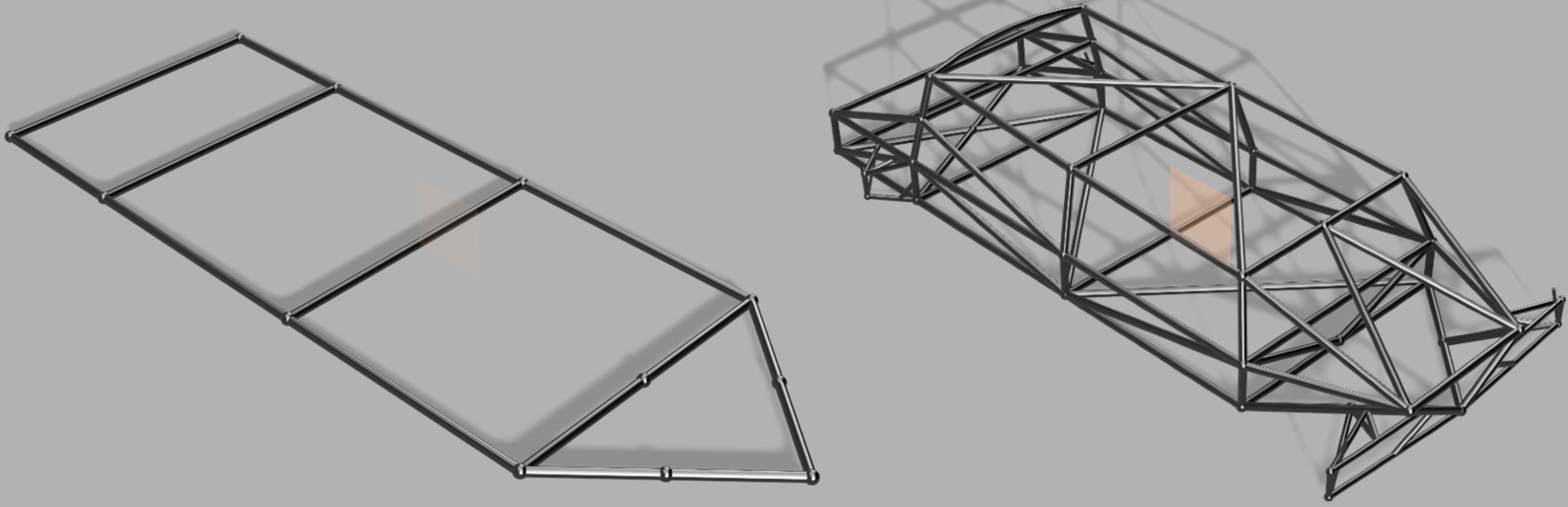
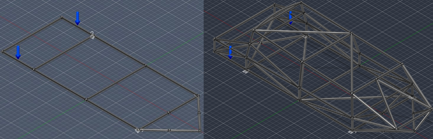
Both chassis configurations were modelled as three-dimensional solid-body assemblies in Autodesk Fusion 360, as in Fig. 3. Each structural member was constructed as a solid cylindrical rod of 30 mm diameter, connected at spherical nodal junction points. Due to the complex intersection of many structural members at nodes, if thin-walled hollow tube geometry was used, there would be significant mesh instability at nodes. Fusion 360 also meshes only with solid tetrahedra and offers no beam or shell elements, so the corrected solid proxy was the available alternative. Modelling members as solid cylinders ensures mesh convergence throughout the assembly. The implications of this simplification are addressed through two correction factors described in the Solid-Proxy Geometry and Correction Factors subsection.
The ladder-frame baseline was designed as a rectangular approximation of a last-mile delivery van chassis of 3000 mm wheelbase and 850 mm track width, comprising of two longitudinal rails connected by four transverse crossmembers. This baseline is deliberately minimal. It includes no diagonal gussets, reinforced crossmembers, or outriggers, so it is not representative of an optimised production ladder frame. It is used as a controlled lower-bound reference that isolates the effect of triangulation, and the comparisons that follow should be read on that basis rather than as a claim about the best achievable ladder-frame design.
The semi-spaceframe was developed iteratively from this baseline using the same primary longitudinal rail span and wheelbase. It was developed with a structural hierarchy as in Fig. 4: primary members carrying global bending and torsional loads (main longitudinal rails, suspension nodes, main roll hoop); secondary members preventing local deformation (diagonal bracing, X-bracing, V-braces); and tertiary members closing structural loops to enable semi-torsion box behaviour (upper members, rear triangulation). This semi-spaceframe design aims to create continuous load paths between suspension nodes while maximising stiffness-to-mass efficiency. For both designs and for all three load cases, mesh-refinement studies were conducted by successively halving the average element size until the primary output changed by less than 2% (torsional stiffness) or 5% (peak payload stress) between successive meshes. Element counts, node counts, mesh sizes, and the converged values for every model and load case are reported in Supplementary Table S1. Final meshes ranged from 61,154 to 377,361 nodes, and the change in peak displacement between the two finest meshes was between 0.18% and 1.61% across all six model and load-case combinations, satisfying the convergence criterion.
Both chassis configurations were assigned linear elastic steel properties throughout as in Table 1, consistent with structural mild steel.
| Property | Value |
| Young’s Modulus (E) | 210 GPa |
| Poisson’s Ratio (ν) | 0.30 |
| Nominal Steel Density | 7850 kg/m³ |
| Corrected Simulation Density | 2402 kg/m³ (= 7850 × 0.306; see Solid-Proxy Geometry) |
| Yield Strength (σy) | 250 MPa |
Analysis was restricted to the linear elastic regime. Modelling post-yield plastic deformation was out of scope as a Linear Elastic Solver was used, so von Mises stress exceeding 250 MPa was treated as a structural failure indicator, consistent with the study objective of evaluating stiffness performance within the elastic operating range. The simulation represents joints with the assumption of perfect bonding between members at all junctions, representing an idealised fully welded connection with no joint compliance.
Solid-Proxy Geometry and Correction Factors
As chassis members were modelled as solid rods of 30 mm outer diameter rather than hollow tubes of 30 mm outer diameter and 2.5 mm wall thickness (inner diameter 25 mm) as would be in a production chassis, two mathematical correction factors were derived to map simulation outputs to the behaviour of hollow steel tube construction.
Density Correction Factor (α=0.306):
A solid tube has a larger cross-sectional area than the equivalent hollow tube so the simulation overestimates chassis mass.
As all members have the same diameter 30mm and wall thickness of 2.5 mm, the ratio between solid and hollow volume for any member is constant, depending only on the fixed cross-sectional area ratio between hollow and solid sections and not member length:
The nominal steel density of 7850 kg/m³ was therefore multiplied by 0.306 to give a corrected simulation density of 2402 kg/m³ (2.402 g/cm³). Since only linear static analysis was performed and inertial effects were not included, density influences mass estimation but does not affect calculated stiffness response, which is governed by Young’s modulus and geometry.
Torsional Constant Correction Factor (β=0.518):
The polar moment of inertia J governs torsional resistance for a circular cross-section. A solid member of the same diameter is torsionally stiffer than the equivalent hollow tube, meaning the simulation underestimates twist angles and displacements. The correction factor is the ratio of hollow to solid polar moment of inertia:
All simulated displacements and twist angles were divided by  to scale the underestimated simulation deformation up to the physically realistic value for the equivalent hollow tube. Since the chassis is fully triangulated and uses uniform member cross-sections, the global stiffness is derived from the same axial flexibility across all load cases. So, this correction factor is applied uniformly to displacements in all directions, across all three load cases and both chassis configurations.
The validity of a single displacement correction factor depends on which deformation mode dominates. For a thin-walled circular section the hollow-to-solid ratio of the second moment of area equals that of the polar moment of inertia,  , so the same factor corrects bending and torsional displacements identically. Axial deformation is governed instead by the cross-sectional area ratio
  (equal to
  ). A purely axial displacement corrected with rather than is therefore under-scaled by at most a factor of
  . This bounds the error case by case. The headline torsional stiffness (Load Case 1) is governed by
  and is corrected exactly, and the ladder-frame payload sag is bending-dominated and corrected exactly by the shared ratio 0.518. Only the semi-spaceframe payload sag, which is carried axially, is under-corrected, and even at the worst-case factor of 1.69 the corrected sag remains far below the ladder-frame values, so the reported comparisons and conclusions are unaffected.
The solid-proxy idealisation is retained because hollow-tube geometry could not be meshed at the dense nodal junctions. Because the member-level bounds above do not by themselves establish that the solid-proxy assembly, with its welded joints and combined loading, reproduces a true hollow-tube model, a representative substructure was modelled both as a solid-proxy assembly with the and corrections and as a true hollow-tube assembly, and the two are compared in Supplementary Table S4.
The ladder-frame structure was used for this comparison because it is a substructure common to both chassis and meshes cleanly in hollow-tube form. The corrected solid-proxy result differs from the true hollow-tube result by 15% in torsional stiffness, by 9% in asymmetric sag and induced twist, and by 6% in symmetric sag, so the correction is accurate to within 15% for this geometry. The deviations are not all in the same sense: the correction understates ladder-frame torsional stiffness and symmetric sag, and overstates asymmetric sag and twist. Because the reported comparisons are ratios between two chassis analysed by the same method, a systematic correction error acts on numerator and denominator together and largely cancels.
Applying the full ladder-frame deviation with no compensating change to the semi-spaceframe, which is the most pessimistic treatment, moves the torsional stiffness ratio from 53.7 to 45.6, the asymmetric sag and twist ratios from 23.3 to 21.3, and the symmetric sag ratio from 28.7 to 30.4. No conclusion of this study depends on that difference.
Boundary Conditions
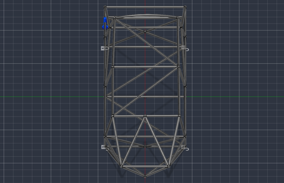
To define each model’s position in space while permitting physically realistic deformation, constraints were applied following the 3-2-1 constraint rule, as in Fig. 5. Over-constraining a FEA model artificially increases apparent stiffness; the 3-2-1 finds a balance as the minimum constraint set required to eliminate rigid-body motion without restricting genuine structural flexibility, allowing the chassis to flex and displace naturally. Three constraint levels were applied at the suspension nodes. The primary anchor at the rear right node was constrained in all three translational directions (X, Y, Z), defining the global coordinate origin. The secondary anchor at the rear left node was constrained in one vertical (Z) and one lateral (Y) direction to prevent planar rotation while allowing lateral expansion and contraction of the chassis width under Poisson’s effect during longitudinal bending. The front support nodes were constrained in the vertical (Z) direction only, representing approximate tyre contact patches that carry the vertical ground reaction force under payload weight while allowing the wheelbase to adjust under longitudinal bending.
Load Cases
Three load cases were simulated, each representing a distinct structural loading scenario critical to the service life of an urban electric delivery vehicle.
Load Case 1: Torsional Loading:
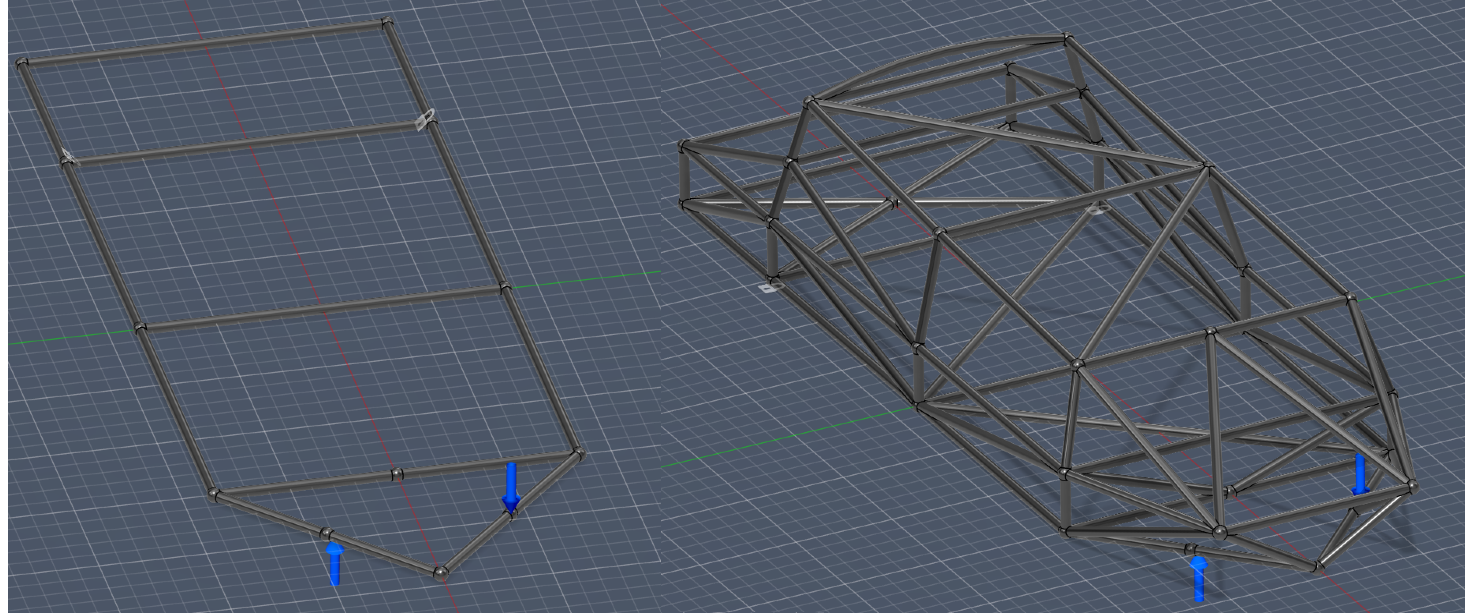
An upward force on one front node and a downward force of equal magnitude on the opposite front node were applied, generating a torsional couple about the vehicle’s longitudinal axis. Both rear suspension mounting nodes were fully constrained in X, Y, and Z.
For this test, the suspension architecture was removed from the semi-spaceframe model to ensure chassis stiffness was isolated from suspension compliance. The track width between the two loaded front nodes was measured as 425.00 mm for both configurations. Four force magnitudes were tested (500, 1000, 1500, and 2000 N per side) to confirm linear elastic response and allow torsional stiffness to be extracted as the gradient of the torque-twist graph. For each force level, the vertical Z-displacement at each front loaded node and the maximum von Mises stress across all members were recorded as primary outputs.
Load Case 2: Asymmetric Payload
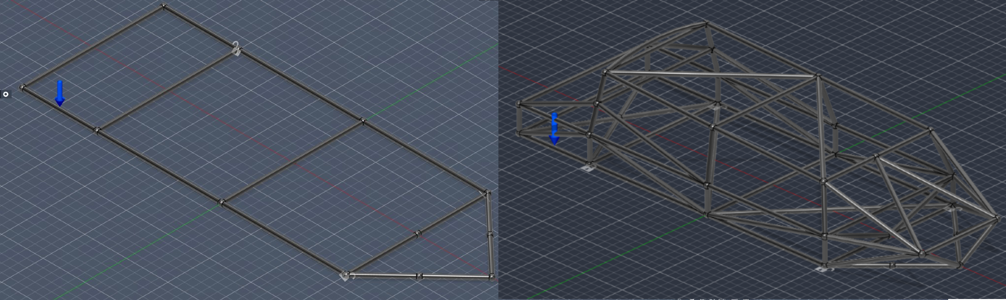
A total load of 800 kg (7848 N) was applied as a distributed load across the rear right longitudinal rail, representing an extreme case of fully one-sided cargo loading at the maximum rated payload of a typical N1-category last-mile delivery van24. The 3-2-1 constraint rule was applied for both chassis. Because the suspension architecture was retained in the semi-spaceframe to ensure realistic load path redirection under payload, the track width between suspension nodes differs: 1035 mm for the semi-spaceframe and 850 mm for the ladder frame. To prevent this track-width difference due to suspension integration from confounding the comparison, the suspension geometry was removed and the asymmetric case was evaluated with both chassis constrained at a common track width, as reported in Supplementary Table S3. From these values, induced twist angle was calculated for each chassis:
This load case tests both longitudinal sag resistance (vertical displacement) and torsional resistance induced by asymmetric loading (calculated induced twist angle). It represents the critical combined loading scenario for urban delivery operations.
Load Case 3: Symmetric Vertical Payload
Using the same setup and constraint methodology as Load Case 2, the 800 kg total load was divided equally across both longitudinal rails (3924 N per side), representing maximum rated payload under a uniform cargo distribution. Maximum Z-displacement at the mid-wheelbase point and von Mises stress were measured to evaluate longitudinal bending stiffness.
Iterative Design Strategy
The semi-spaceframe chassis was developed through iterative geometric modifications informed by FEA and specific structural principles to progressively transform chassis behaviour, using a ladder frame baseline as the performance floor. Iterations were evaluated under identical torsional loading (1000 N per side) to isolate the influence of geometric modification on structural behaviour. Modifications followed a sequence of resolving floor-plane instability, developing 3D torsional loops, and integrating suspension nodes15. Each iteration was first evaluated using two qualitative FEA indicators: whether the location of maximum von Mises stress had shifted away from bending-dominated rail members toward nodal regions (indicating more distributed axial load transfer), and whether the torsional deformation mode was more restrained across the floor plane. Quantitative performance metrics were also recorded for all iterations.
Evaluation Metrics
Torsional Stiffness (K) (Nm/deg): Torsional Stiffness is the measure of a chassis’ ability to resist twisting forces along its longitudinal axis and is used to quantify handling precision.
Torque is calculated as in (9), from the applied force and track width between loaded nodes:
The simulation twist angle was computed from the total vertical displacement δ between the two front nodes:
This was divided by the torsional constant correction factor β to give the real hollow-tube angle:
This was repeated across all four force levels and a graph of torque against correct twist angle was plotted, with the gradient being torsional stiffness.
Specific Stiffness (Nm/deg/kg): Specific stiffness is the Torsional Stiffness per unit mass in each chassis. Chassis mass was reported directly by the Fusion 360 solver using the corrected simulation density of 2402 kg/m³. This will evaluate if performance improvement comes from structural optimisation rather than from simply adding material.
Vertical Displacement (sag): Vertical Displacement is measured as the maximum Z-displacement at the midpoint of the wheelbase. As it is also a simulation displacement, it is corrected by dividing the raw simulation displacement by the correction factor of 0.518.
Von Mises Stress: Von Mises stress reduces the three-dimensional stress tensor to a single equivalent scalar stress for direct comparison with the material’s uniaxial yield strength25. Three stress quantities are reported at stated probe locations. The peak nodal stress at the constraint is classified as a numerical singularity, and excluded as a reported maximum, if it increases monotonically under local mesh refinement without converging. The hot-spot stress, probed one tube diameter (30 mm) from the joint, is required to converge to within 5% and is used as the criterion for local yield. The nominal member stress, probed at member mid-length, characterises general member utilisation26. A configuration is judged to yield if its converged hot-spot stress exceeds the 250 MPa yield strength. Fusion 360 reports element-averaged nodal stress by default, so the quoted peak values are already averaged-element quantities and the unaveraged peak would be higher still, which does not affect the singularity classification. The mesh-refinement evidence for each probe location is given in Supplementary Table S2.
Results
Iterative Design Progression
Iteration 0 (Baseline). The ladder-frame baseline comprised of two longitudinal rails of approximately 3000 mm span connected by four transverse crossmembers at a track width of 850 mm, as in 3, where its rectangular bays provide minimal resistance to in-plane shear and torsional loads are resisted mostly through bending of the longitudinal rails. The FEA confirmed this bending-dominated behaviour: maximum von Mises stress of 142.7 MPa was concentrated at the rail-to-crossmember junctions and a corrected twist angle of 10.9° was recorded, representing the largest of all iterations.
Iteration 1 (Floor-Plane Triangulation). Iteration 1 added diagonal members in the floor plane connecting opposite corners of each rectangular bay to form two triangles per bay, helping achieve stability against in-plane shear, transitioning the bays from bending-dominated rectangles to axially dominated triangulated units to significantly increase the chassis’ baseline resistance to lateral deformation and distribute the load across the frame rather than concentrating at individual crossmember junctions. Maximum von Mises stress reduced by 14.9% and corrected twist angle reduced by 25.1%, showing improved torsional resistance.
Iteration 2 (Side Bay Triangulation and Upper Rail Introduction). Iteration 2 introduced vertical side members connecting the floor rail nodes to a new upper rail and diagonal members within each side bay triangulating the resulting rectangular side panels. The upper rail established a parallel longitudinal load path above the floor plane so loads entering at the suspension nodes could now distribute between the lower rail in compression and the upper rail in tension, developing the structure toward a closed-section frame. The triangulation through side diagonals also aims to protects the rectangular side bays against vertical shear, allowing them to maintain stability under asymmetric load. Torsional stiffness increased from 52.1 to 241 Nm/deg. The migration of stress away from longitudinal rail midspans toward diagonal member intersections indicates a transition from bending-dominated to axial-dominated structural behaviour where the diagonal members engaged as axially-loaded elements, distributing load into the triangulated network rather than concentrating it in the rails.
Iteration 3 (Semi-Torsion Box & Perimeter Completion). Iteration 3 targeted the absence of a closed upper surface, forming a semi-torsion box. By closing the upper surface of the cross-section, the structure acquired a semi-closed perimeter. As a result, the combination of floor diagonals, side diagonals, and upper crossmembers creates a shear-flow path around the cross-section perimeter, approximating the closed-section behaviour described by Bredt’s formula13. Since torsional stiffness is proportional to the enclosed area squared divided by perimeter, even a partially closed loop generates a substantial improvement in torsional resistance compared to the fully open structure. Torsional stiffness increased by 342.7%, showing that rather than the frame twisting as an open-section mechanism with large differential displacement between left and right rails, the deformation was now more distributed across the full frame cross-section. This suggests the side and floor diagonal members engaged in alternating tension and compression to effectively resist the applied torsional force, seen as the maximum twist angle reduced by 77.4% relative to Iteration 2.
Iteration 4 (Local Node Stabilisation and Perimeter Completion). Iteration 4 targeted local stress concentrations in suspension nodes and open end bays. The frontal V-braces helped stabilise the front suspension node region against the highly concentrated forces introduced at that point as without this stabilisation, the concentrated load was forced to travel through the adjacent longitudinal rail in bending before reaching a triangulated region. The V-brace creates two direct axial load paths from the node into the floor triangulation, distributing the concentrated force and removing the bending path. With maximum structural stress reducing from 64.7 MPa in Iteration 3 to 54.1 MPa, this significantly reduced front node stress concentrations. The rear X-bracing closed the open rear perimeter, preventing independent warping of the rear frame ends under torsional loading and contributing to the large increase in torsional stiffness to 2129 Nm/deg.
Iteration 5 (Suspension Integration). Iteration 5 addressed the rear suspension node geometry and the suspension integration. A double-wishbone suspension architecture was integrated at both front and rear nodes. While the suspension geometry itself was not the subject of structural optimisation in this study, its integration at nodes of the semi-spaceframe was important to avoid stress concentration that arises if suspension pickup points fall on unsupported rail spans rather than at structural nodes15. Diagonal members were added from each rear suspension mounting node into the surrounding triangulated floor and side regions, ensuring that concentrated forces entering through the rear suspension path were immediately distributed into axial members rather than being channelled into the longitudinal rail as bending loads. Comparing to Iteration 1, stress was now distributed across the full triangulated network at low uniform levels rather than concentrated in bending-dominated longitudinal rails. Maximum von Mises stress of 54.1 MPa represents a factor of safety of 4.6 against yield, so no single member approaches the material limit under torsional loading.
| Iteration | Modification | K (Nm/deg) | (°) | Max (MPa) | K Improv. |
| 0: Ladder Frame | Rails/crossmembers | 39.6 | 10.9 | 142.7 | Baseline |
| 1: Floor Triang. | Floor diagonals | 52.1 | 8.16 | 121.3 | +31.6% |
| 2: Side Triang. | Upper rails/sides | 241 | 1.76 | 174.5* | +363% |
| 3: Semi-Torsion | Upper crossmembers | 1067 | 0.398 | 64.7 | +343% |
| 4/5: Semi-Spaceframe | V-braces, suspension | 2129 | 0.201 | 54.1 | +100% |
(*Peak value is a load-application singularity (defined under Evaluation Metrics) with probed nominal structural stress being 60-70 MPa).
The data reveals two inflection points in structural behaviour: the introduction of three-dimensional load paths in Iteration 2 and the torsional loop closure via the semi-torsion box in Iteration 3. These two modifications are therefore identified as the primary architectural drivers of semi-spaceframe torsional efficiency, consistent with the structural theory established earlier.
Torsional Stiffness Comparison
| Force (N) | Torque (Nm) | Max σ (MPa) | δ (mm) | θ_sim (°) | θ_real (°) |
| Semi- Spaceframe | |||||
| 500 | 212.5 | 27.0 | 0.384 | 0.0518 | 0.100 |
| 1000 | 425 | 54.1 | 0.768 | 0.104 | 0.201 |
| 1500 | 637.5 | 81.1 | 1.153 | 0.155 | 0.299 |
| 2000 | 850 | 108.2 | 1.537 | 0.207 | 0.400 |
| Ladder Frame | |||||
| 500 | 212.5 | 71.3 | 21.0 | 2.83 | 5.46 |
| 1000 | 425 | 142.7 | 41.9 | 5.63 | 10.9 |
| 1500 | 637.5 | 214.0 | 62.8 | 8.41 | 16.2 |
| 2000 | 850 | 285.4 | 83.8 | 11.2 | 21.6 |
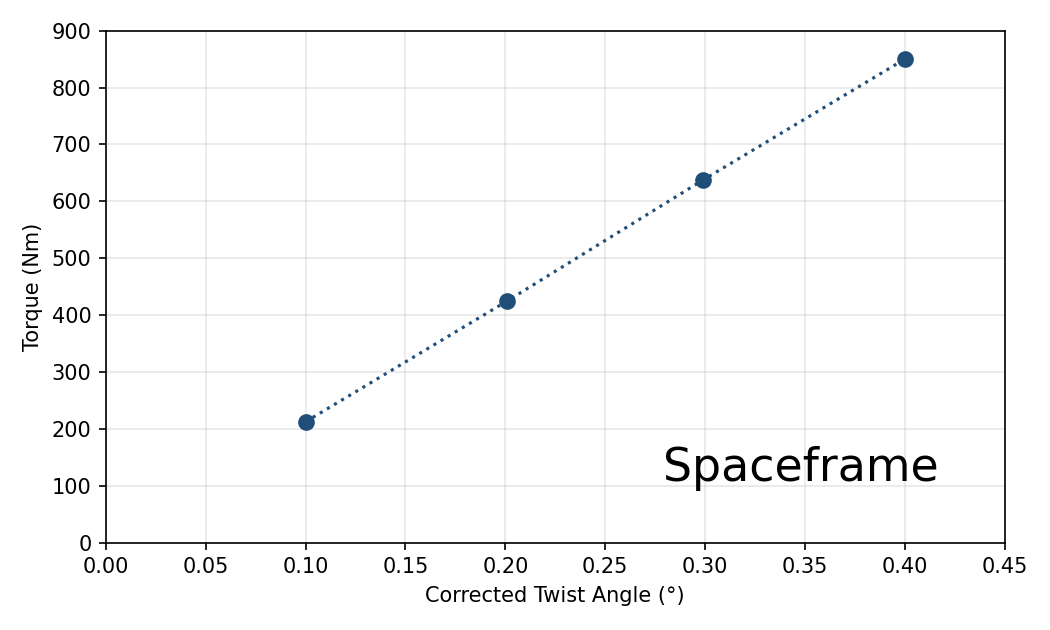
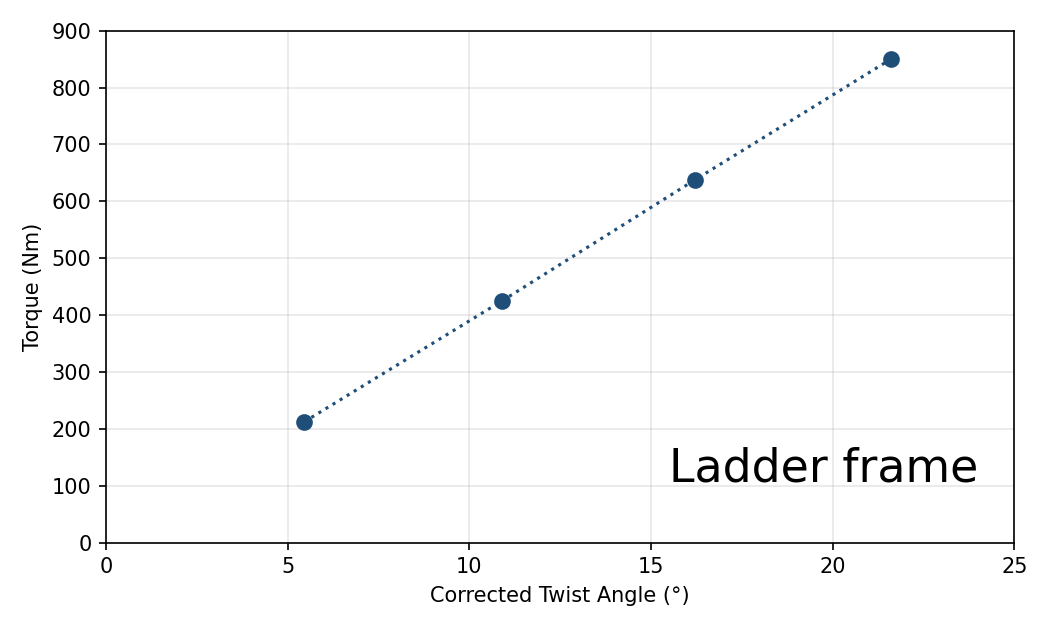
Linear regression of torque against corrected twist angle yielded:
This represents a 53.7 increase in torsional stiffness. The regression intercepts are negligible relative to the data range and  in both cases, confirming that the response is elastically linear and that the correction factor has been applied consistently.
To make the correction chain explicit for one data point, consider the semi-spaceframe at 1000 N per side. The raw simulation vertical displacement between the two front nodes is  mm over the 425.00 mm loaded-node spacing, giving a simulation twist angle
  . Dividing by the torsional correction factor gives the corrected angle
  . The applied torque is
  Nm, so the single-point stiffness is
  Nm/deg. The 2129 Nm/deg reported above is the gradient of the linear regression across all four force levels, so every reported
  value is a post-correction quantity.
Looking at the stress distribution at 1000 N per side helps picture the physical mechanism underlying this difference. In the semi-spaceframe, stress is distributed across the full triangulated network with a maximum of just 54.1 MPa. All members remain well below the yield strength of 250 MPa, giving a factor of safety of 4.6 against yield. This suggests the floor diagonal members are engaged in alternating axial tension and compression, actively resisting the applied torsional couple by preventing rectangular bay distortion. In the ladder frame however, maximum stress reaches 142.7 MPa at the rail-crossmember junctions, concentrated at discrete points along the longitudinal rails where bending moment is highest. The rear rails of the ladder frame carry negligible stress, confirming that load is carried by bending of the lower rails only. At 1500 N per side, the ladder frame’s maximum stress reaches 214.0 MPa, approaching the yield threshold, while the semi-spaceframe remains at 81.1 MPa with substantial safety margin remaining.
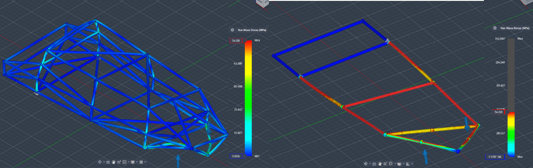
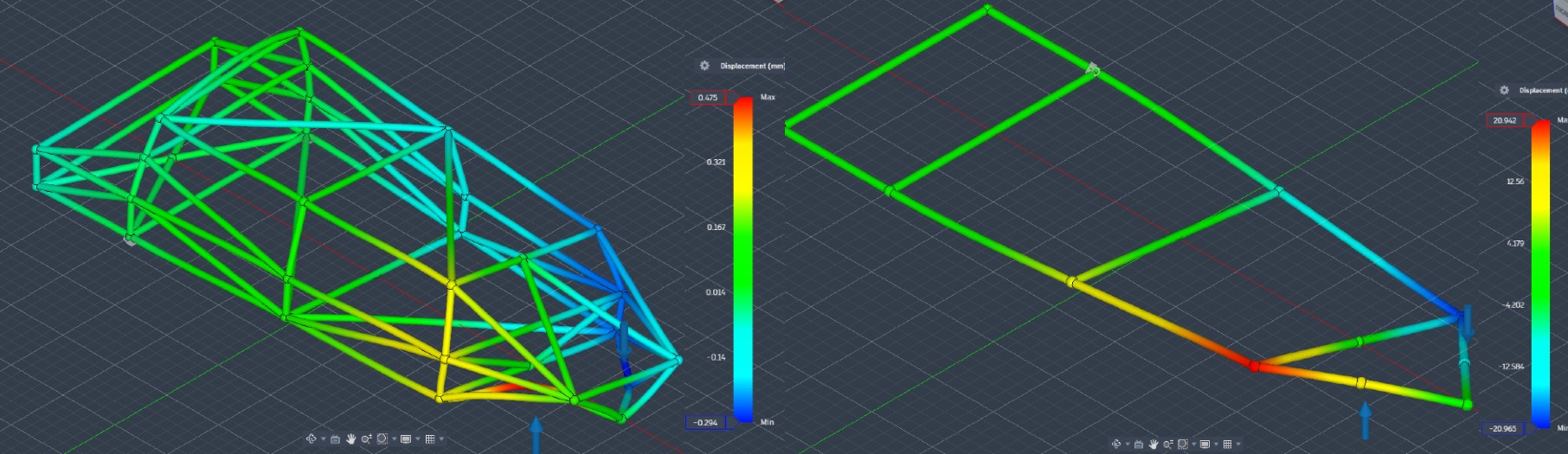
Figure 10 | Torsional loading FEA results: stress distribution (top) and displacement (bottom)
Asymmetric Payload Test Results
| Metric | Ladder Frame | Semi-Spaceframe | Improvement |
| Corrected Max Sag (mm) | 31.5 | 1.35 | 23.3× reduction |
| Max von Mises Stress (MPa) | 942.2* | 222.3* | – |
| Induced Twist Angle (°) | 2.12 | 0.0910 | 23.3× reduction |
*Ladder frame stress of 942.2 MPa substantially exceeds yield strength (250 MPa), indicating structural failure under this load case. **Both peak values are mesh-divergent and excluded as singular by the criterion in Evaluation Metrics. The converged hot-spot stress is 815 MPa for the ladder frame, 3.3 times yield, and 115 MPa for the semi-spaceframe, a factor of safety of 2.17. Probe data are given in Supplementary Table S2.
The ladder frame experiences a 31.5 mm deflection, which over a 3000 mm wheelbase means the loaded rail has deformed far beyond what a linear elastic analysis can meaningfully describe. The von Mises stress of 942.2 MPa is 3.77× the yield strength. Local mesh refinement shows that this peak is itself singular, but the converged hot-spot stress one tube diameter from the loaded joint is 815 MPa, still 3.3 times yield, while the nominal member stress is only 180 MPa. The failure is therefore local to the unbraced joint rather than a general overload of the members, which is precisely the condition that triangulation removes. The induced twist angle of 2.12° is likely sufficient to influence suspension alignment and attached body structures. These observations suggest structural inadequacy in the adapted ICE ladder frame with the 800 kg asymmetric payload condition representative of a maximum in urban delivery operations.
The semi-spaceframe’s corrected sag of 1.35 mm and induced twist of 0.0910° fall within the elastic safety margin. The sag and twist ratios agree at 23.3×, confirming that the twist advantage reflects structural behaviour rather than track geometry. This comparison is reported in Supplementary Table S3. This test suggests that the side-truss architecture effectively distributed the asymmetric load across multiple axial members simultaneously, preventing the concentrated deflection of a single loaded rail that dominates the ladder frame response.
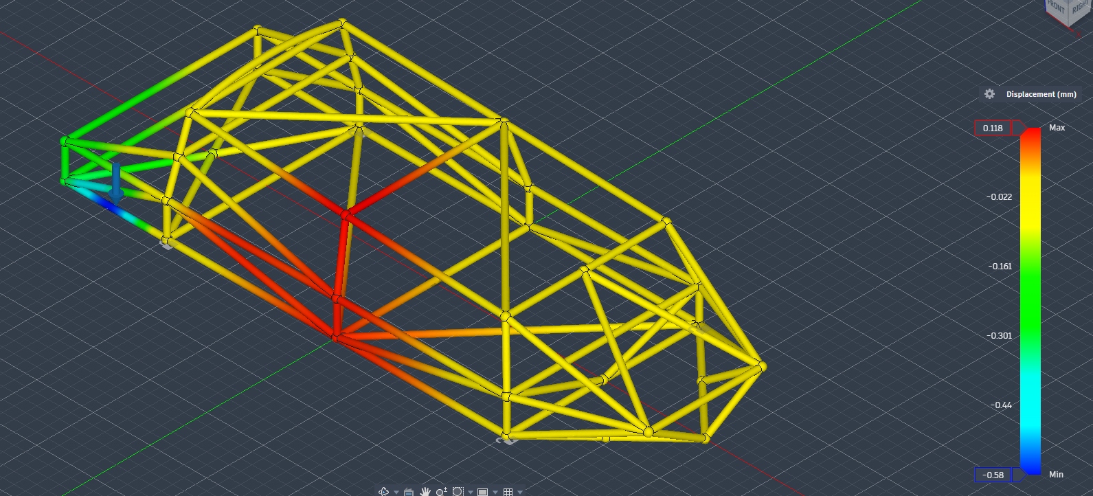 correction. Tabulated in Supplementary Table S3.
Symmetric Vertical Payload Test Results
| Metric | Ladder Frame | Semi-Spaceframe | Improvement |
| Corrected Max Sag (mm) | 20.3 | 0.708 | 28.7× reduction |
| Max von Mises Stress (MPa) | 532.4* | 110.3 | – |
*Note: Ladder frame stress of 532.4 MPa exceeds yield strength, indicating plastic deformation under symmetric payload at maximum rated capacity.
The ladder frame’s corrected sag of 20.3 mm under symmetric loading exceeds the elastic limit, indicating the adapted ladder frame cannot carry 800 kg of evenly distributed payload without permanent structural deformation, suggesting potential safety implications for commercial delivery operation. The semi-spaceframe’s 0.708 mm corrected sag, by contrast, represents a deflection of 0.020% of the wheelbase which is well within the elastic safety margin and would likely produce no measurable change in suspension geometry. The symmetric values reported here are likewise taken from the matched track-width configuration, with both chassis constrained at 850 mm and the suspension architecture removed (Figure 12).
The semi-spaceframe’s side-truss architecture was the primary structural mechanism enabling this performance. By converting vertical floor loads into axial tension and compression across the three-dimensional triangulated framework, the side trusses engaged the full cross-sectional depth of the chassis in resisting the bending moment, effectively functioning as a deep beam rather than two shallow rails15. The neutral axis of this equivalent deep beam is located at mid-height of the semi-spaceframe’s cross-section, substantially further from the extreme fibres than in a ladder frame rail, reducing maximum bending stress in proportion to the increased section depth.
While battery behaviour was not directly modelled, battery cell deformation has been identified as a potential trigger for thermal runaway in lithium-ion systems under repeated mechanical stress27, suggesting chassis stiffness may impact battery safety. Therefore, the semi-spaceframe’s 0.708 mm deflection may help ensure the battery housing integrated within the floor structure remains isolated from significant structural flex.
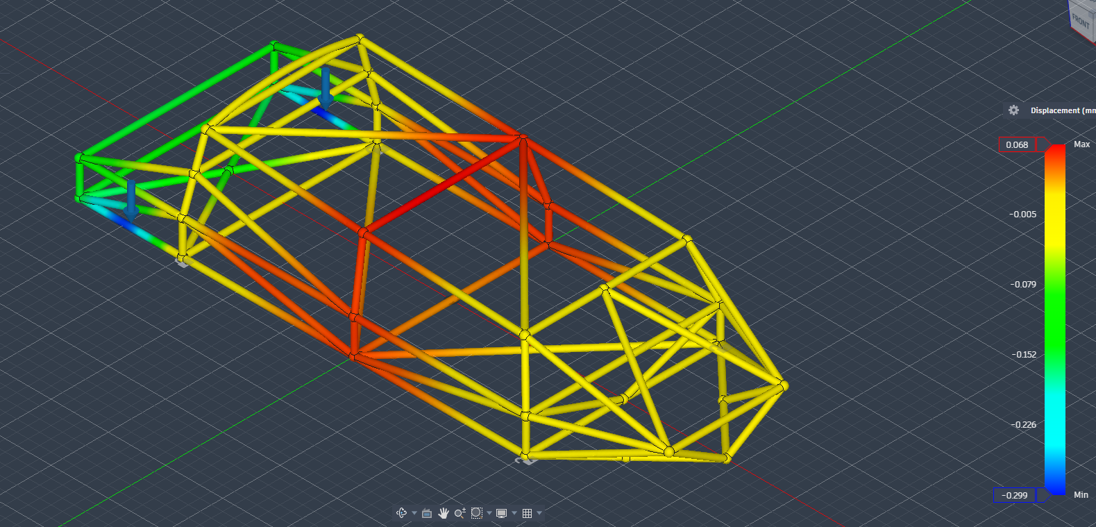
Specific Stiffness & Efficiency
| Metric | Ladder Frame | Semi-Spaceframe | Ratio |
| Torsional Stiffness K (Nm/deg) | 39.6 | 2129 | 53.7× |
| Chassis Mass m (kg) | 33.3 | 157 | 4.71× |
| Specific Stiffness K/m (Nm/deg/kg) | 1.19 | 13.6 | 11.4× |
The greater mass of the semi-spaceframe reflects the greater number of structural members required for full three-dimensional triangulation. If the torsional stiffness improvement came purely from mass addition, specific stiffness would be constant – however, there is an 11.4× improvement in stiffness per unit mass, confirming that the 53.7× increase in torsional stiffness is driven primarily by geometric triangulation and structural loop closure rather than just by material addition. This specific-stiffness comparison already normalises for the quantity of material, because both chassis use the same corrected density and so the mass ratio equals the ratio of steel volume. It does not normalise for structural scope, since the semi-spaceframe spans a larger three-dimensional envelope with more members by design. The ratio is therefore evidence that triangulation adds stiffness faster than it adds mass, not a claim that the two structures occupy the same design scope.
As range in battery-electric vehicles is inversely proportional to total vehicle mass, a chassis that achieves higher specific stiffness enables equivalent structural performance at lower overall vehicle weight, directly extending operational range for a given battery capacity. Therefore, this improvement suggests that purpose-built triangulated architectures may be able to improve both structural performance and range efficiency simultaneously.
| Metric | Ladder Frame | Semi-Spaceframe | Improvement |
| Torsional Stiffness (Nm/deg) | 39.6 | 2129 | 53.7× |
| Specific Stiffness (Nm/deg/kg) | 1.19 | 13.6 | 11.4× |
| Asymmetric Sag (mm) | 31.5 | 1.35 | 23.3× |
| Asymmetric Twist (°) | 2.12 | 0.0910 | 23.3× |
| Symmetric Sag (mm) | 20.3 | 0.708 | 28.7× |
Discussion
This study investigated the hypothesis that a lightweight triangulated semi-spaceframe chassis architecture produces measurably superior structural efficiency compared with a conventional ladder-frame baseline under variable payload loading conditions representative of urban electric delivery operations. The FEA results confirm this hypothesis across all evaluated metrics. The hypothesis has three testable elements. First, that torsional stiffness improves, which is confirmed by the 53.7× increase. Second, that resistance to asymmetric and symmetric payload improves, which is confirmed by the 23.3× smaller induced twist and the 23 to 29× smaller sag, with the semi-spaceframe remaining elastic where the minimal baseline yields. Third, that the improvement comes from geometry rather than added mass, which is confirmed by the 11.4× gain in specific stiffness.
The optimised semi-spaceframe achieved a 53.7× increase in torsional stiffness (2129 vs 39.6 Nm/deg), a 23.3× reduction in induced twist under asymmetric 800 kg loading, and a 28.7× reduction in vertical sag under symmetric maximum payload. Critically, the ladder frame exceeded material yield in both payload test cases while the semi-spaceframe maintained elastic operation with factors of safety above 2.0 throughout. These results confirm that the minimal, unbraced adapted ladder frame used here as a lower-bound reference is structurally inadequate for these loading conditions at maximum rated payload. They do not establish that an optimised, appropriately braced ladder frame would fail in the same way, so the comparison is best read as bounding the benefit of triangulation rather than as a verdict on all ladder-frame designs.
The 11.4× improvement in stiffness per unit mass confirms that the performance gains are attributable primarily to geometric triangulation rather than to material addition. The iterative design data identifies three-dimensional load path introduction and torsional loop closure as the two architectural features responsible for the largest structural improvements, each producing stiffness gains exceeding 340% in a single design step.
These results are consistent with the structural theory previously established. The torsional improvements across each iteration produced by progressive closure of the structural perimeter are consistent with Bredt’s formula, in which torsional stiffness scales with enclosed area squared13. The stress distribution patterns observed in the FEA outputs confirm the bending-to-axial transition as the colour gradient characteristic of bending stress (high at extreme fibres, zero at neutral axis) visible in the ladder frame results is replaced by the uniform colour distribution characteristic of axially loaded members in the semi-spaceframe results.
However, several modelling assumptions constrain the range of validity of these results and ability for them to be generalised. The analysis was restricted to the linear elastic regime, excluding post-yield plastic deformation and buckling, which are the primary failure modes in thin-walled semi-spaceframes under crash loading. Furthermore, load cases were static, whereas urban delivery operations involve dynamic impact loads, road-induced vibration, and repeated fatigue cycling that static FEA cannot capture. Joints were modelled as perfectly bonded rigid connections, whilst in a real chassis, weld-bead geometry and heat-affected zones introduce localised compliance and reduced yield strength that are hence not represented in the simulation8. Also, the use of solid-proxy geometry, although corrected by mathematically derived factors, introduces an assumption of uniform cross-sectional deformation scaling that may not hold precisely at high-density nodal junctions where local stress fields are complex. Lastly, the ladder frame baseline was a simplified approximation rather than a specific commercial vehicle geometry. Although this limits direct comparison to production platforms, it helps preserve the generalisability of the architectural comparison. All quantitative results are finite-element predictions rather than experimentally validated values, so the specific ratios reported here should be read as model predictions. The load cases are also static, whereas urban delivery duty applies dynamic loads that can reach 1.5 to 2.5 times the static value through road irregularities, kerb drops, and braking6. Dynamic amplification would scale the reported stresses and deflections and reduce the effective factors of safety, although the relative ranking of the two architectures would be preserved. Fatigue is likewise outside the static analysis. Under the high-cycle, variable-amplitude loading of stop-start routes, the members carrying the largest stress ranges, the floor and side diagonals near the suspension nodes, would be the most fatigue-critical, and assessment against the categorised S-N curves for welded tubular steel in BS 7608 and Eurocode 328,29 is needed before the architecture is taken to production.
Beyond structural safety, the 0.708 mm sag under full symmetric payload has relevance to EV battery integrity. Chassis deflection transmits mechanical strain to floor-integrated battery housings, which when repeated across time, accelerates electrochemical degradation and has been identified as a contributing factor in thermal events in lithium-ion systems27. The rigidity demonstrated here hence suggests that purpose-built semi-spaceframe architectures can also provide some additional battery protection without extra dedicated battery casing reinforcement.
The modularity of the semi-spaceframe architecture also offers a practical manufacturing advantage. The three-tier structural hierarchy can allow for targeted reinforcement for different payload capacities by modifying secondary and tertiary members without having to redesign the primary load paths, which may make the architecture viable across a range of last-mile delivery vehicle classes without requiring platform-specific redesign. This modularity is balanced by a manufacturing cost that the ladder frame does not carry. Each node requires jig fixturing and multiple weld beads in confined geometry, and the semi-spaceframe has many more tube-to-tube joints than the two-rail baseline, so weld count, inspection effort, and the sensitivity of as-built stiffness to nodal tolerance all rise20. These are practical constraints on commercial viability and would need to be weighed against the structural gains.
Three broader conclusions follow from these findings. First, chassis architecture governs structural performance more strongly than material quantity in this load regime. Second, the semi-torsion box configuration achieves torsional resistance approaching that of a fully closed section while retaining the manufacturing accessibility of an open structure, making it a practically viable platform for commercial delivery vehicles. Third, the structural rigidity demonstrated has other benefits for EV-specific requirements: battery isolation from mechanical strain, stable suspension geometry under variable cargo loading, and a scalable modular architecture adaptable to different vehicle classes.
Future work should address the limitations of the current study through dynamic FEA incorporating road-induced vibration and fatigue loading, nonlinear analysis capturing post-yield behaviour and buckling modes, and physical scale-model testing to empirically validate the simulated torsional stiffness improvements. A formal parametric study varying diagonal member angles and member counts, which would identify which individual modification contributes most per unit mass added, is a further avenue that the present iterative sequence does not resolve. Integration of the battery housing as a structural floor element could be a further development opportunity in which battery mass contributes to floor shear stiffness rather than being carried as dead load, potentially improving specific stiffness beyond the values demonstrated here23.
The results of this study provide a simulation-based structural case for purpose-built triangulated architectures in electric delivery vehicle design, demonstrating that geometric optimisation of chassis architecture offers a route to simultaneous improvement in structural performance, vehicle mass efficiency, and battery safety, all objectives of increasing importance as electrification of urban logistics accelerates.
Supplementary Information
References
- European Commission. Zero-emission urban freight logistics and last-mile delivery. https://transport.ec.europa.eu/transport-themes/urban-transport/zero-emission-urban-freight-logistics-and-last-mile-delivery_en. 2021. [↩]
- World Health Organisation. Road traffic injuries. https://www.who.int/news-room/fact-sheets/detail/road-traffic-injuries. 2023. [↩]
- H. Christian, S. Tan. Utilizing existing vehicle’s ladder frame design for electric vehicle platform as an alternative to a dedicated skateboard-style design. Engineering Headway. Vol. 38, pg. 255-263, 2026, https://doi.org/10.4028/p-lQkKn7. [↩] [↩]
- B. Heissing, M. Ersoy. Chassis handbook. Vieweg+Teubner Verlag, 2011. [↩] [↩] [↩]
- K. Shahrezaei, C. J. O’Reilly, T. Lähivaara, P. Göransson. Transport efficiency of delivery trucks: a study. Proceedings of the Design Society. Vol. 3, pg. 3631-3640, 2023, https://doi.org/10.1017/pds.2023.364. [↩]
- O. Zamzam, A. A. Ramzy, M. Abdelaziz, T. Elnady, A. A. Abd El-Wahab. Structural performance evaluation of electric vehicle chassis under static and dynamic loads. Scientific Reports. Vol. 15, Article 5168, 2025, https://doi.org/10.1038/s41598-025-86924-w. [↩] [↩] [↩]
- J. M. Gere, B. J. Goodno. Mechanics of materials (8th ed.). Cengage, 2012. [↩] [↩] [↩] [↩]
- J. Happian-Smith. An introduction to modern vehicle design. Butterworth-Heinemann, 2002. [↩] [↩] [↩] [↩]
- J. Reimpell, H. Stoll, J. W. Betzler. The automotive chassis: engineering principles (2nd ed.). Butterworth-Heinemann, 2001. [↩] [↩]
- S. Ganesh, S. Venkatesan. Evolution of flexible modular electric vehicle platforms among automotive. International Journal of Vehicle Structures & Systems. Vol. 13, No. 3, 2021, https://doi.org/10.4273/ijvss.13.3.24. [↩] [↩]
- W. U. H. Paul, A. S. Siddiqui, S. Kirmani, R. A. Khan. Techno-economic assessment of electric vehicles in India: evaluating BAAS models, ICE parity, and next-generation platforms. Journal of Advanced Education and Sciences. Vol. 6, No. 2, pg. 1-13, 2026, https://doi.org/10.64171/JAES.6.2.1-13. [↩]
- W. Afzal, R. Alim Mufti. Optimal cross-section of cross member for increased torsional and bending stiffness of ladder frame chassis. 16th International Bhurban Conference on Applied Sciences and Technology (IBCAST). pg. 218-228, 2019, https://doi.org/10.1109/IBCAST.2019.8667195. [↩] [↩]
- D. E. Malen. Fundamentals of automobile body structure design (2nd ed.). SAE International, 2011. [↩] [↩] [↩]
- R. D. Cook, D. S. Malkus, M. E. Plesha, R. J. Witt. Concepts and applications of finite element analysis (4th ed.). Wiley, 2001. [↩]
- W. F. Milliken, D. L. Milliken. Race car vehicle dynamics. SAE International, 1995. [↩] [↩] [↩] [↩]
- Y. Liu, C. Liu, X. Gao, J. Tan. Multiphysics finite element analysis and optimization of load-bearing frame for pure electric SUVs. Symmetry. Vol. 17, No. 7, pg. 1143, 2025, https://doi.org/10.3390/sym17071143. [↩]
- Z. Wu, W. Pan, R. Niu, L. Liu. Frame design and improvement of a small electric vehicle. Mechanical Sciences. Vol. 16, pg. 263-272, 2025, https://doi.org/10.5194/ms-16-263-2025. [↩]
- M. Cavazzuti, A. Baldini, E. Bertocchi, D. Costi, E. Torricelli, P. Moruzzi. High performance automotive chassis design: a topology optimization based approach. Structural and Multidisciplinary Optimization. Vol. 44, pg. 45-56, 2011, https://doi.org/10.1007/s00158-010-0578-7. [↩]
- J. Costa, D. Vilela. Formula SAE frame torsional stiffness study using FEA. SAE Technical Paper 2014-36-0234, 2014, https://doi.org/10.4271/2014-36-0234. [↩]
- A. Eakambaram, P. Baskara Sethupathi, M. A. Saibalaji, A. Baskar. Experimental analysis and validation of torsional stiffness of a tubular space frame chassis. Materials Today: Proceedings. 2021, https://doi.org/10.1016/j.matpr.2021.02.238. [↩] [↩]
- R. Capata, L. Martellucci, D. Buccolini, C. De Felice, M. Giannini. Validation method of torsional stiffness for a single-seater car chassis. World Electric Vehicle Journal. Vol. 16, No. 11, pg. 604, 2025, https://doi.org/10.3390/wevj16110604. [↩]
- B. A. Gala, D. Munani, K. P. Mandaliya, T. Talekar, H. Vasudevan, V. H. Khatawate. Numerical investigation of chassis torsional stiffness for Formula Student vehicles. Journal of Mines, Metals and Fuels. Vol. 73, No. 6, pg. 1651-1662, 2025, https://doi.org/10.18311/jmmf/2025/48770. [↩]
- Y. Liu, Z. Yang, X. Huang, J. Tan. A review of cell-to-body (CTB) battery-structure integration design for electric vehicles. Frontiers in Mechanical Engineering. Vol. 12, 2026, https://doi.org/10.3389/fmech.2026.1825484. [↩] [↩]
- European Union. Regulation (EU) 2018/858 on the approval and market surveillance of motor vehicles and their trailers (vehicle category N1). Official Journal of the European Union, 2018. [↩]
- R. von Mises. Mechanik der festen Körper im plastisch-deformablen Zustand. Nachrichten der Gesellschaft der Wissenschaften zu Göttingen. pg. 582-592, 1913, http://resolver.sub.uni-goettingen.de/purl?PPN252457811_1913. [↩]
- E. Niemi, W. Fricke, S. J. Maddox. Structural hot-spot stress approach to fatigue analysis of welded components: Designer’s guide (2nd ed.). Springer, 2018, https://doi.org/10.1007/978-981-10-5568-3. [↩]
- Z. Chai, J. Li, Z. Li, Z. Liu, X. Jin. Experimental analysis and safety assessment of thermal runaway behavior in lithium iron phosphate batteries under mechanical abuse. Scientific Reports. Vol. 14, Article 8673, 2024, https://doi.org/10.1038/s41598-024-58891-1. [↩] [↩]
- British Standards Institution. BS EN 1993-1-9:2005, Eurocode 3: Design of steel structures — Part 1-9: Fatigue. BSI, 2005. [↩]
- British Standards Institution. BS 7608:2014+A1:2015, Guide to fatigue design and assessment of steel products. BSI, 2015. [↩]