
Abstract
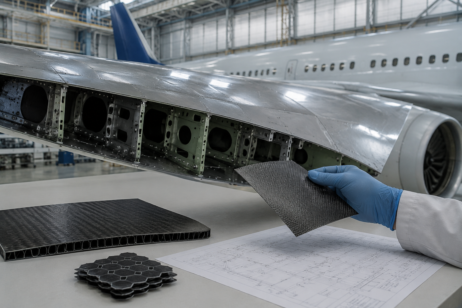
The study examines performance improvements achieved through Carbon Fiber Reinforced Polymer (CFRP) use in commercial aviation, particularly aircraft like Boeing 787-9, and whether partial substitution of CFRP and aluminum components with Graphene-Reinforced Composites (GRC) may reduce structural mass without redesigning the aerodynamic profile of the wing. Therefore, this paper presents an evaluation if GRC may influence aircraft performance characteristics such as range and endurance for such aircraft. Those are the structural parts which have the greatest possibility for material replacement – skin, stringers, ribs, and selected internal structures – which have been analyzed for possible weight saving as well as their effects on performance. Approximate mass distribution based on publicly available estimates and material density information are employed in determining how much weight can be saved; its effect on performance is calculated from the Breguet range and endurance equations. The analysis, based on scaled estimates derived from publicly available Boeing 787-8 structural data, resulted in an estimated weight saving of 5,300 kg, and about 370 kilometers of additional range, and 25 minutes more endurance under conservative assumptions, based on proportional scaling using Breguet equation. GRC may represent a promising direction for future aerospace materials research with two major challenges today: cost and certification. The study provides a preliminary assessment of the potential impact of GRC on aircraft efficiency and performance. Therefore, the model is intended as a first-order approximation rather than a validated engineering model.
Keywords: Graphene-Reinforced Composites; CFRP; Aircraft Structures; Weight Reduction; Breguet Equation; Aerospace Materials; Aviation.
Introduction
Modern history has witnessed a rather radical change in the structural design of aircraft over the last hundred years1. Early aircraft designs used materials such as aluminum that would become favored for their strength-to-weight advantages and easy availability to serve as structural elements. In long strength, aluminum kept its dominance over aircraft structures by representing close to about 50% of an airplane’s weight2,3. Nevertheless, in the 2000s Boeing decided to make use of composites in commercial aviation expressly to enhance performance; among these, Carbon Fiber Reinforced Polymer (CFRP) drew much attention due to being 20-30% less weighty than aluminum4,5, having fatigue and corrosion resistance properties6, and having a good strength-to-weight ratio7. These benefits have set an entirely different path in modern aircraft design, from improving structural efficiency to aerodynamic performance8. CFRP has thus become one of the baseline materials used for constructing modern commercial planes. CFRP will serve one of its most crucial applications in the aircraft wing, which has to play multiple roles. Apart from generating lift and having aerodynamic as well as structural loads, it doubles up very efficiently as an internal fuel tank – this is referred to as a ‘wet wing’ design9. The successful application of CFRP in wing structures immediately translates into extended range and endurance with reduced fuel consumption for any similar Boeing 787-9 case study; hence, this immediately places a direct impact on engineering benefits concerning economic gain10. Though engineering has significantly improved after the discovery of CFRP, this probably does not mark the ultimate frontier in technology. Breakthroughs in material science, of course, and also the fact that several new tests with various materials have been conducted, which might at some point replace CFRP, are the factors on which further increases in aircraft range and endurance depend11. More efficient materials will likely be the ones to introduce such further improvements in range and endurance2. Out of a great deal of advanced materials, one, which has shown promising potential during experimental studies is Graphene Reinforced Composite (GRC)12,13. What GRC brings to the table is an even higher strength-to-weight ratio than CFRP14, as well as better fatigue resistance, toughness15, plus multifunctionality because of graphene nanoplatelets inside the polymer matrix16,17. Material properties for GRC have shown significant potential in laboratory studies18, data taken from published experimental and NASA studies19,20; however, it isn’t yet quite applicable on a wide scale for large load-bearing aerospace structures due to many issues concerning manufacturing scalability, long-term performance and certification challenges21,22,23. GRC presents readiness for selective use in non-critical or secondary structural elements – such as wing skins, ribs, and control surfaces that may contribute to structural mass while carrying lower primary loads compared with spars and the center wing box.24,25,26 This potentially opens up an avenue through which aircraft performance metrics like range and endurance can be improved through targeted material substitutions while staying compliant with established certification standards and consistent with fundamental flight physics27,28,29. This paper studies how substituting some selective components of the wings of Boeing 787-9 with GRC would affect its performance, assuming constant structural load requirements. More specifically, it will replace those parts not responsible for bearing loads, like wing skins, stringers, ribs, trailing edge components, and all aerodynamic control surfaces, but keep the wing spars and the fuel tank structure. During the last twenty years, several studies discussed the mechanical and structural advantages of using CFRP in aerospace applications, relating it to an improvement in lift-to-weight ratio which automatically leads to reduced fuel consumption30,31. However, recent literature has opened a door for newer composites, or rather graphene-based materials, to be considered as further steps in high-performance aircraft structures32. The objective is to quantify what potential structural weight reduction can be realized by such material substitution and what corresponding improvements in range and endurance can be achieved or assessed. The paper also discusses real-world practical challenges of using GRC, specifically manufacturability, cost, and certification, to help keep the approach in balance.21,33
Methodology
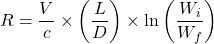
This study uses a theoretical model to compare two different approaches to see if it is possible to get better results by substituting GRC for CFRP in parts of the wing structure of the Boeing 787-91. In fact, the Boeing 787-9 was selected as the case because it represents one of the first large commercial aircraft with extensive use of composite materials, where CFRP accounts for up to roughly 50% of structural weight2,1,34. More so, its structure and mass breakdowns, as well as adequately documented aerodynamic performance, make up a transparent dataset with which one can judge at the aircraft level what results from substituting material. Thus, by choosing such a method, any effects observed would result from material substitution if there were no geometric or aerodynamic changes. Since detailed Boeing 787-9 component mass data are not publicly available in open literature, the study relies on publicly accessible analytical datasets derived from Boeing 787-8 structural breakdown estimates, using secondary sources such as Lissys Ltd1,35. These values are used as approximate engineering proxies and scaled to represent the larger Boeing 787-9 configuration. This introduces uncertainty and should be interpreted as a simplified modeling assumption rather than official manufacturer data. The change in aircraft performance is calculated under the assumptions of no aerodynamic redesign, a constant fuel load, and unchanged load paths. Since data for aircraft structures is still relatively new, this paper applies analytical modeling to its theoretical work rather than experimental testing10. Components selected for potential material substitution were limited to secondary wing structures such as skins, ribs, stringers, and selected control surface elements7. These components typically carry distributed aerodynamic and local structural loads, while the primary load-bearing elements of the wing – including the main spars and the central wing box – remain responsible for the majority of bending and torsional loads. To maintain a conservative and realistic modeling approach, the research assumes that only secondary structural components could be considered for early-stage composite substitution, while the primary load-bearing structures remain unchanged9. Material property estimates to feed into the analysis for GRC have been derived from published works, while performance evaluation takes place in terms of two very concrete measures36,37. Range (R) represents the maximum horizontal distance an aircraft can cover with a given fuel load. Endurance (E) represents the maximum time an aircraft can remain in flight under steady conditions concerning power and efficiency. They are both fuel efficiency parameters related through the Breguet Range (eq. 1) and Endurance (eq. 2) equations, which directly relate operational performance with lift-to-drag ratio and weight characteristics1,38. In this research, the Breguet equations are applied under standard simplifying assumptions of steady cruise, approximately constant velocity and lift-to-drag, and fixed representative TSFC. Both range and endurance equations are considered to provide complementary performance perspectives because weight reduction affects both the flight distance and loiter capability. This study estimates how structural weight reductions could influence range and endurance in long-haul flight conditions.
(1) 
(2) 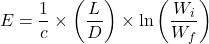
Equations (1) and (2) include several main variables:  , the cruise speed;
  , the thrust-specific fuel consumption (TSFC);
  , the lift-to-drag ratio;
  , the initial weight of the aircraft with full fuel; and
  , the final weight of the aircraft after fuel is consumed. Changes in the initial aircraft weight result from a reduction in structural mass achieved through the use of lighter material, which directly influences both range and endurance. After estimating the mass savings resulting from the GRC substitution and incorporating these values into the Breguet equations, performance enhancements can be evaluated.
Material Property Comparison
A comparison of material properties was performed to see if GRC could replace CFRP in aircraft structures (Table I). GRC has a lower density than CFRP and aluminum, as well as higher tensile strength and stiffness. These traits imply that it could reduce structural weight without hurting the aircraft’s performance parameters. This makes GRC a possible option for replacing less vital wing parts that don’t go through as much stress. A simple sensitivity check was performed for GRC density. If density is increased from 1,350 to 1,400kg/m3 the predicted mass saving decreases, which correspondingly reduces the range gain. This indicates that the results are moderately sensitive to assumed material density. The data for this analysis were obtained from existing aerospace material papers and studies on nanocomposites, representing laboratory-scale or early-stage material data rather than production-ready GRC20.
| Property | Aluminum | CFRP | GRC |
| Density (kg/m³) | ~2,780 | ~1,600 | 1,350 |
| Tensile Strength | ~400 MPa | ~600-800 MPa | >900 MPa |
| Young’s Modulus | ~70 GPa | ~70-120 GPa | >150 GPa |
| Fatigue Resistance | Moderate | High | Excellent (if graphene is well-dispersed) |
| Corrosion Resistance | Low | High | Very High |
| Multifunctionality | None | Low | High (electrical, thermal) |
Wing Mass Estimation and Substitution Scope
| Component Group | Original Material | Replaced With | Mass Replaced (tones) | Mass after replacement (tones) | Mass saved (tones) |
| Flaps, Ailerons, Slats, Spoilers | Aluminum | GRC | 4.5 | 2.2 | 2.3 |
| Wing Skin, Ribs, Stringers | Carbon Fiber Reinforced Polymer (CFRP) | GRC | 19.3 | 16.2 | 3 |
| Total | – | GRC | 23.7 | 18.4 | 5.3 |
To evaluate the performance impact of substituting aluminum and CFRP components with GRC, this section presents the full methodology and step-by-step approach of analytical modeling using equation no. 1 and equation no. 2. The Boeing 787-9 was used for all computations, with realistic weight data and suitable aerodynamic assumptions. The total wing mass is roughly 32,120 kg, which is based on scaled values from the Boeing 787-8 mass report, where the wing group is 12.61% of the aircraft’s MTOW (254,692 kg). Based on structural breakdown models and public data for the Boeing 787 family, the proper parts were selected for possible material substitution. Aluminum and CFRP were replaced with GRC in several non-primary structural parts, such as control surfaces and outer skin elements, as seen in Table II. Primary load-bearing structures, like spars and center wing box, were not included in the substitution scope due to their important function in the structural integrity of the wing.
Lift-to-Drag Ratio Adjustment
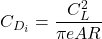
The Boeing 787-9’s lift-to-drag ratio during cruise is around 20.8. This is similar to what other wide-body planes get, which is usually between 20 and 2120. This number was used as the baseline value for aerodynamic performance analysis. Upon changing it from 20.5 to 21.1, the plane’s estimated range changed by less than 2% in either direction. This indicates that the analysis is not overly sensitive to small changes in this value. This ratio is a critical parameter in assessing the aircraft’s aerodynamic performance, as it directly relates to its fuel efficiency and range. A higher lift-to-drag ratio indicates that the aircraft can generate more lift with less drag, enabling it to fly farther on the same amount of fuel. This confirms that the exact choice of 20.8 does not significantly alter the conclusions1. A reduction in structural mass decreases wing loading, which in turn lowers the induced drag. Using standard aerodynamic relations, the induced drag coefficient can be expressed as:
(3) 
(4) 
where  is the induced drag coefficient,
  is the lift coefficient,
  is Oswald efficiency factor (
 ),
),  is the aspect ratio of the wing (
 ) for wide body aircraft,
  is the aircraft weight,
  is the dynamic pressure, and
  is the wing planform area39. For constant flight speed and wing area, induced drag varies with the square of weight:
(5) 
Since total drag is the sum of parasite,  , and induced,
  , components:
(6) 
And in long-range cruise, it is reasonable to assume that under this balance condition, the ratio of new to old lift-to-drag after a structural weight reduction can be written as:
(7) 
For the present case, the analytical estimate is  20.82, representing a change of less than 0.2% compared to the baseline 20.8. For comparison, some preliminary design texts also cite a simple rule-of-thumb approximation:
(8) 
which yields an approximate value of ~21.0 using simplified rule-of-thumb relation. Equation (7) is retained for the primary analysis because it is based on the induced-drag decomposition introduced in Equations (3)-(6), whereas equation (8) is used as a rule of thumb upper bound comparison39. The primary driver of the predicted range increase is the reduction in aircraft weight, which improves the logarithmic weight ratio term in the Breguet range equation. Consequently, even a small structural weight reduction can produce a larger percentage increase in range. Thus, the following 2.6% range increase is not attributed to the small L/D change alone, but primarily to the change in the weight ratio term.
Estimating Specific Fuel Consumption
For the performance calculations, a representative cruise-condition TSFC value of approximately 0.45 kg/(N·hr) was used based on published performance data for engines used on the Boeing 787-9, including the Rolls-Royce Trent 1000 and GE GEnx-1B.A value of 0.45 kg/(N·hr) was used as a representative cruise parameter in the Breguet range calculations40. The back-calculated TSFC value of approximately 0.446 kg/(N·hr) was obtained as a consistency check and was not used as an independent validation of the model10.
Final Breguet Analysis (Post-Substitution)
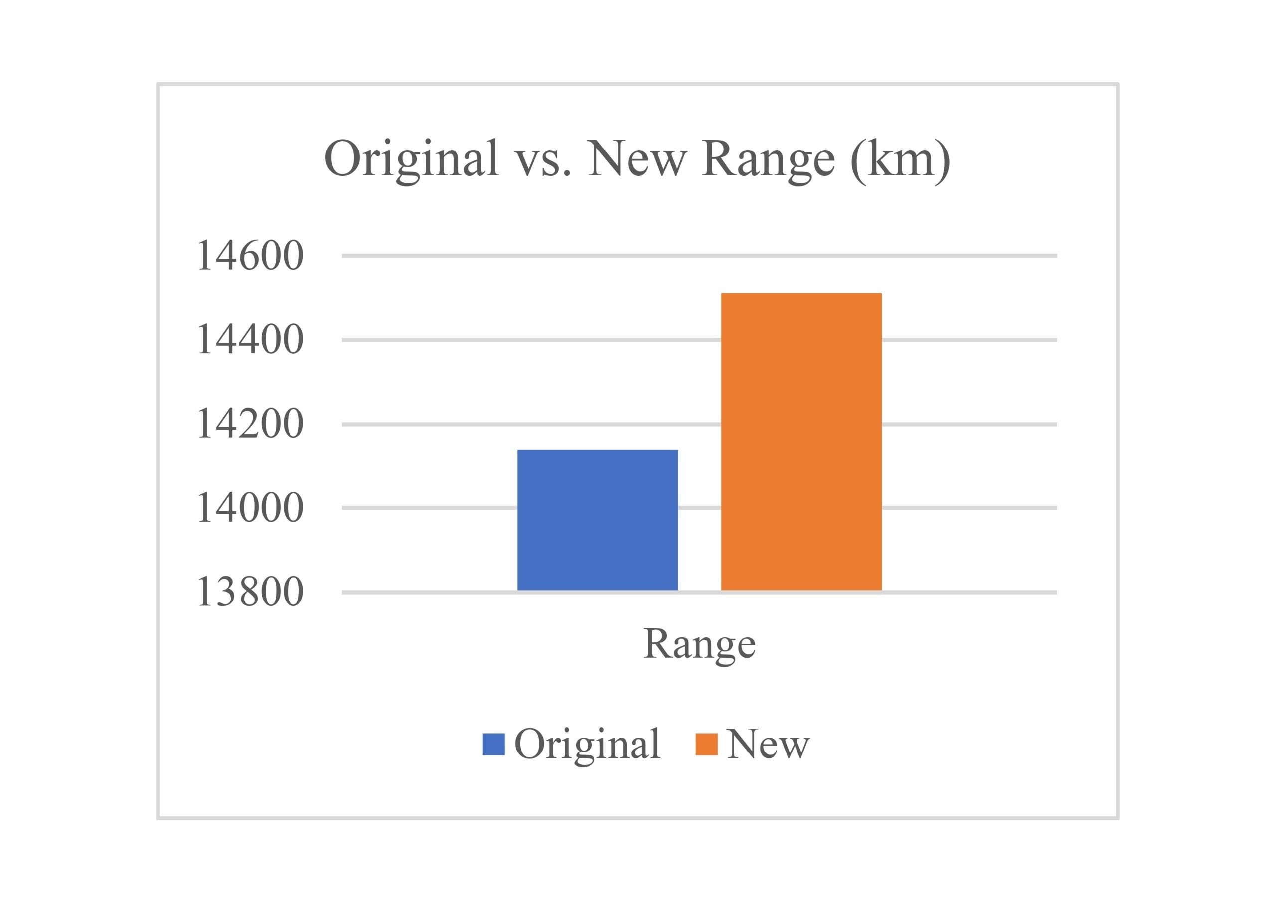
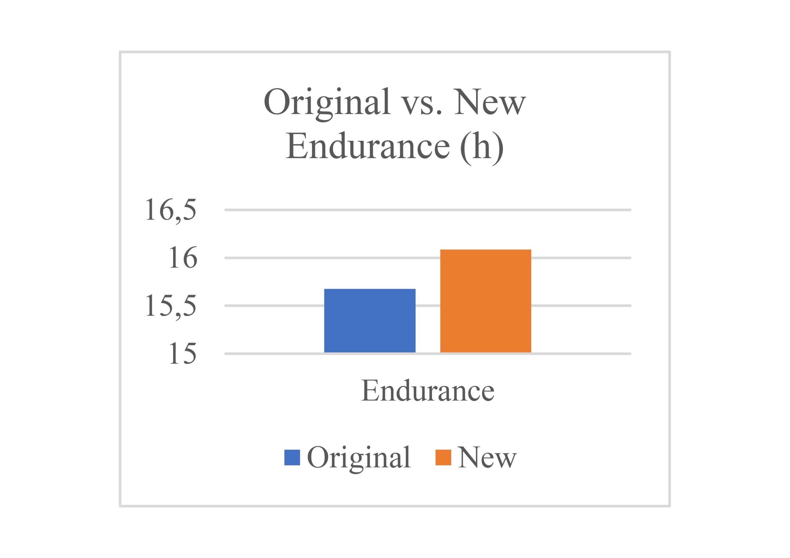
Using the updated aircraft parameters after considering the substitution of selected aluminum and CFRP components with GRC, the analysis was carried out with the cruise TSFC taken as fixed at 0.45 kg/(N·hr), consistent with published engine performance data. The lift-to-drag ratio was adjusted to 20.82 based on the conservative recalculation. The difference between the corresponding initial and final weight after substitution shows a total structural weight reduction of 5.3 tones. This value was inserted into the Breguet range and endurance equations and the predicted aircraft performance showed a moderate increase. The range grew from 14,140 km to approximately 14,512 km, which corresponds to ~2.6% of improvement. The endurance increased from 15.68 h to about 16.09 h, representing an improvement of roughly 0.41 h (~25 minutes). These results show that performance improvement primarily results from reduced aircraft weight, which improves the logarithmic weight ratio term in the Breguet range equation, while the change in aerodynamic efficiency (L/D) remains relatively small. On the other hand, if a less conservative estimate was taken, the gains would rise to nearly +500 km in range and +0.55 h in endurance. However, the conservative outcome based on L/D 20.82 is retained for the primary conclusions of this study.
Assumptions and Limitations
This analysis assumes no changes to the aircraft’s aerodynamic design, meaning that only material substitution is considered. The load paths within the wing structure are preserved, where only non-critical components: skins, ribs, and control surfaces are replaced, and main structural elements like spars and the center wing box remain unchanged. The challenges of graphene dispersion, uniformity, and large-scale manufacturing are not explicitly modeled in the numerical calculations; however, they substantially limit the practical applicability of the results and are treated as major real-world constraints. Certification, safety, and practical implementation aspects are discussed in the final section of the paper. In addition, the study assumes ideal atmospheric conditions and doesn’t account for operational factors such as headwinds, alternate routes, or holding patterns. Ultimately, these effects could slightly reduce the derived performance gains, but they do not significantly alter the potential benefits of GRC. The analysis does not model changes in center of gravity, structural dynamics, aeroelastic response, or load redistribution, all of which could influence aircraft performance parameters. Furthermore, the substitution model is based on density values and does not include laminate re-sizing, directional allowable, buckling, impact tolerance, or aeroelastic constraints, which means that the resulting mass estimates should be interpreted as conceptual rather than structurally certified values24,25.
Results
The substitution of selected non-critical wing components with GRC resulted in an estimated structural mass reduction of approximately 5,300 kg. This implementation reduced the aircraft’s maximum takeoff weight (MTOW) from 254,692 kg to 249,412 kg and the maximum zero fuel weight (MZFW) from 181,437 kg to 176,156 kg. The aircraft’s lift-to-drag ratio (L/D) improved from 20.8 to ~20.82. The cruise speed (c) and thrust-specific fuel consumption (TSFC) were maintained at 902 km/h and 0.45 kg/(N·h), respectively. The impact of mass reduction on aircraft range is visualized in FIGURE 1, which shows a 370 km increase after material substitution, and the endurance increased by about 25 minutes as shown in FIGURE 2. For that reason, it suggests the hypothesis that GRC substitution in non-critical wing components could lead to different improvements in aircraft range and endurance without requiring aerodynamic redesign.
Discussion
This study suggests that replacing low-load-bearing aluminum and CFRP components of the Boeing 787-9 wing with GRC could imply measurable performance improvements in range and endurance without changing the aerodynamic design. The larger percentage of mass reduction for aluminum components arises from the greater density contrast between aluminum and GRC, whereas CFRP is already relatively lightweight, therefore the substitution yields smaller fractional savings2,7. Using the theoretical improvements, the study can also state that such improvements could have an impact on long-haul aircraft, where little enhancements would have a substantial economic and environmental impact over time28. This selection is intended as a conservative conceptual scope, not as a formal certification assessment. The improvement in the lift-to-drag (L/D) ratio from 20.8 to approximately 20.82-21.0 reflects reduced induced drag from lower wing loading39. The TSFC stayed almost constant since the propulsion systems were unchanged, suggesting that any gains came mostly from weight changes, not from better system efficiency10. This work represents a small step forward, improving on current designs, instead of a full change, like Boeing’s use of composite wings on the 787. Although multifunctional behavior is discussed in the literature, it is not analyzed in this study and is not considered a demonstrated benefit. Several limits need mentioning: first, the work uses scaled weight guesses from Boeing 787-8 data and public density data, which adds doubt because there is no exact public data on the 787-9’s parts’ weights. Second, making and approving large amounts of GRC is still hard. Lab results look good, but graphene spread, cost, and how it holds up over time are still being studied. It also assumes perfect flight conditions and steady fuel use, which might not match real flights. Still, the results show material changes are a good way to boost aircraft performance without major design changes. The work supposes that GRC can be added in certain spots to improve efficiency without needing a total redesign of the plane’s shape or structure. Also, using GRC could keep or even increase fuel space in future wing designs because it can be both light and strong. More work could use more exact hybrid analysis and load tests to check this idea25. Lastly, studying the environmental impact and cost over its life would give a fuller view of how good GRC is for future planes. Previous studies on composite substitution in aircraft structures similarly show modest, but meaningful efficiency gains from mass reduction41. While direct comparisons are limited by different aircraft classes and assumptions, the present estimates fall within the same qualitative range of incremental performance improvement27.
Conclusion
This research aimed to evaluate whether the partial substitution of CFRP and aluminum components with GRC in the Boeing 787-9 wing structure could lead to any major improvements in performance. The hypothesis was that such a substitution would reduce MTOW and improve efficiency without requiring an aerodynamic redesign. Based on mass breakdown analysis, material properties, and application of the Breguet range and endurance equations, the results support this hypothesis. A mass reduction of approximately 5,300 kg was achieved, with an estimated increase of 370 km in range and 25 minutes in endurance. This study suggests that GRC substitution in non-primary wing components may offer performance gains through structural mass reduction under simplified analytical assumptions. Ultimately, this study contributes to the understanding of how next-generation composites may provide potential for incremental improvement in the boundaries of aircraft range and endurance through mass reduction within the constraints of modern aerospace design.
Acknowledgement
Thank you for the guidance of Pooja Nema, mentor from the Technical University of Munich, in the development of this research paper.
References
- Raymer, D. P. Aircraft Design: A Conceptual Approach. AIAA, 2018, pp. 20–40, 450–470 [↩] [↩] [↩] [↩] [↩] [↩]
- Mouritz, A. P. Introduction to Aerospace Materials”. Woodhead Publishing, 2012, Ch. 2–4 [↩] [↩] [↩] [↩]
- Soutis, C. (2005). Fibre Reinforced Composites in Aircraft Construction. Progress in Aerospace Sciences, 41(2), 143–151. [↩]
- Campbell, F. C. “Manufacturing Processes for Advanced Composites”. Elsevier, 2003, pp. 1–20 [↩]
- Katnam, K. B., da Silva, L. F. M., & Young, T. M. (2013). Bonded Repair of Composite Aircraft Structures. Composite Structures, 105, 153–165. [↩]
- Hale, J. M., et al. (2016). Advanced Composite Materials in Aerospace Engineering. Aerospace, 3(2), 12. [↩]
- Kassapoglou, C. “Design and Analysis of Composite Structures”. Wiley, 2013, pp. 10–25 [↩] [↩] [↩]
- Marsh, G. (2004). Airbus A350 and Boeing 787: The New Generation of Composite Airliners. Reinforced Plastics, 48(2), 26–29. [↩]
- Niu, M. C. Y. “Airframe Structural Design”. Conmilit Press Ltd., 1999, Ch. 3–5 [↩] [↩]
- Gudmundsson, S. “General Aviation Aircraft Design.” Butterworth-Heinemann, 2014, pp. 450–470 [↩] [↩] [↩] [↩]
- Green, J. E. (2003). Civil Aviation and the Environment. Journal of Aircraft, 40(5), 781–789. [↩]
- Lee, C., Wei, X., Kysar, J. W., & Hone, J. (2008). Measurement of the Elastic Properties and Intrinsic Strength of Monolayer Graphene. Science, 321(5887), 385–388. [↩]
- Stankovich, S., et al. (2006). Graphene-Based Composite Materials. Nature, 442(7100), 282–286. [↩]
- Potts, J. R., Dreyer, D. R., Bielawski, C. W., & Ruoff, R. S. (2011). Graphene-Based Polymer Nanocomposites. Polymer, 52(1), 5–25. [↩]
- Zhu, Y., et al. (2010). Graphene and Graphene Oxide: Synthesis, Properties and Applications. Advanced Materials, 22(35), 3906–3924 [↩]
- Kuilla, T., Bhadra, S., Yao, D., Kim, N. H., Bose, S., & Lee, J. H. “Recent Advances in Graphene Based Polymer Composites.” Progress in Polymer Science, vol. 35, no. 11, 2010, pp. 1350–1375 [↩]
- Compton, O. C., & Nguyen, S. T. (2010). Graphene Oxide, Highly Reduced Graphene Oxide and Graphene. Small, 6(6), 711–723. [↩]
- Balandin, A. A., et al. (2008). Superior Thermal Conductivity of Single-Layer Graphene. Nano Letters, 8(3), 902–907. [↩]
- Rafiee, M. A., Rafiee, J., Srivastava, I., Wang, Z., Song, H., Yu, Z.-Z., & Koratkar, N.“Enhanced Mechanical Properties of Nanocomposites at Low Graphene Content.”ACS Nano, vol. 3, no. 12, 2009, pp. 3884–3890. [↩]
- Papageorgiou, D. G., Kinloch, I. A., & Young, R. J. “Mechanical Properties of Graphene and Graphene-Based Nanocomposites.” Progress in Materials Science, vol. 90, 2017, pp. 75–127 [↩] [↩] [↩]
- Kim, H., Abdala, A. A., & Macosko, C. W. “Graphene/Polymer Nanocomposites.” Macromolecules, vol. 43, no. 16, 2010, pp. 6515–6530. [↩] [↩]
- Baker, A., Dutton, S., & Kelly, D. (2004). Composite Materials for Aircraft Structures. Progress in Aerospace Sciences, 40(6), 317–349. [↩]
- Campbell, F. C. (2010). Structural Composite Materials in Aerospace Design. Materials Today, 13(11), 30–37. [↩]
- Jones, R. M. “Mechanics of Composite Materials”. Taylor & Francis, 1999, pp. 50–100 [↩] [↩]
- Daniel, I. M., & Ishai, O. “Engineering Mechanics of Composite Materials.” Oxford University Press, 2005, pp. 120–150 [↩] [↩] [↩]
- Yokozeki, T., et al. (2018). Development of Carbon Fiber Composite Structures for Commercial Aircraft. Advanced Composite Materials, 27(1), 1–15. [↩]
- Dababneh, O., Kipouros, T., & Whidborne, J.“Aircraft Weight Reduction Using Composite Materials: A Study of Performance Benefits.” Aerospace Science and Technology, vol. 76, 2018, pp. 111–121. [↩] [↩]
- Hassan, M., et al. “Use of Composite Materials in Aircraft Structures and Their Impact on Performance.” Journal of Aerospace Engineering, vol. 29, no. 4, 2016. [↩] [↩]
- Scholz, D., & Seresinhe, R. (2014). Fuel Efficiency of Modern Commercial Aircraft. Aircraft Engineering and Aerospace Technology, 86(1), 20–27. [↩]
- Kuilla, T., Bhadra, S., Yao, D., Kim, N. H., Bose, S., & Lee, J. H. “Recent Advances in Graphene Based Polymer Composites.” Progress in Polymer Science, vol. 35, no. 11, 2010, pp. 1350–1375. [↩]
- Zhao, X., & Zhao, Y. (2018). Impact of Structural Weight Reduction on Aircraft Fuel Consumption. Aerospace Science and Technology, 72, 311–320. [↩]
- Abrate, S. (2011). Impact Engineering of Composite Aircraft Structures. Composite Structures, 93(7), 1750–1758. [↩]
- Singh, V., Joung, D., Zhai, L., Das, S., Khondaker, S. I., & Seal, S. “Graphene Based Materials: Past, Present and Future.” Progress in Materials Science, vol. 56, no. 8, 2011, pp. 1178–1271 [↩]
- Boeing.“Composite Materials in the 787 Dreamliner.” [↩]
- Lissys Ltd.“Boeing 787-8 Mass Breakdown.” [↩]
- Rafiee, M. A., Rafiee, J., Srivastava, I., Wang, Z., Song, H., Yu, Z.-Z., & Koratkar, N.“Enhanced Mechanical Properties of Nanocomposites at Low Graphene Content.”ACS Nano, vol. 3, no. 12, 2009, pp. 3884–3890 [↩]
- Papageorgiou, D. G., Kinloch, I. A., & Young, R. J. “Mechanical Properties of Graphene and Graphene-Based Nanocomposites.” Progress in Materials Science, vol. 90, 2017, pp. 75–127. [↩]
- MIT OpenCourseWare.“Breguet Range Equation.” [↩]
- Anderson, J. D. “Aircraft Performance and Design.” McGraw–Hill, 1999, Ch. 5–6 [↩] [↩] [↩]
- Rolls-Royce. “Trent 1000 Fact Sheet.” [↩]
- Mouritz, A. P., Gellert, E., Burchill, P., & Challis, K. (2001). Review of Advanced Composite Structures for Naval Ships and Aerospace Applications. Composite Structures, 53(1), 21–42. [↩]