
Abstract
Driven by technological advancements, the rocket industry is rapidly growing. However, constructing rockets costs millions of dollars, so many people turn to model rockets as an affordable alternative to learn about aerodynamics. One of the most important parts of a launch vehicle is its fins, which improve the rocket’s stability and may even indirectly improve the apogee. This study investigates the Clipped Delta Fin and certain modifications that may improve model rocket performance, while providing an affordable and accessible way to understand the aerodynamics of fins. Three fins were created with different modifications: curving the leading edge (Fin A), removing a portion of the trailing edge (Fin B), and negatively sweeping the leading edge (Fin C). The authors hypothesized that compared to the Clipped Delta, Fin A would yield superior performance across all metrics; Fin B would reduce max velocity, apogee, and stability; and Fin C would result in lower performance measurements. To test their hypothesis, they used OpenRocket Simulation, which allowed them to create and test their fin models. Within the OpenRocket conditions modeled, Fin B produced a slightly higher simulated apogee and a lower trajectory-deviation indicator than the Clipped Delta, though the small magnitude of these differences and the limitations of the aerodynamic model prevent definitive real-world performance conclusions. Fin C generally performed below the Clipped Delta on these measures. Fin A was excluded from direct comparison to the Clipped Delta because it could not be optimized. Although these tests can certainly be developed further, this study provided a cost-effective way of studying the aerodynamics of fins and revealed how their modifications affect a model rocket’s performance.
Keywords: aerospace, engineering, experimental, aerodynamics, model rockets, fins
Introduction
Over the past century, launch vehicles have transformed from small, short-ranged vehicles to large, heavily fueled machines capable of traveling immense distances and speeds, even into outerspace1. In the late 1960s, the Apollo missions launched, demonstrating the capabilities of launch vehicles in the new space frontier. However, launch vehicles capable of spaceflight come at a heavy price; the Apollo program as a whole cost on the order of hundreds of billions of dollars in inflation-adjusted terms. Alternatively, affordable model rockets now cost less than 100 USD FY20262. Model rockets offer students a safer and cheaper way to learn about launch vehicles and the aerodynamic forces that affect them3. The knowledge gained through model rocket research allows people to test promising theories before utilizing them on real launch vehicles.
Fins are an essential part of all model rockets, providing stability and maintaining a rocket’s orientation during flight. Once launched, changes in the air can cause a rocket to deviate from its intended course; fins help maintain a stable trajectory and minimize erratic flight. A straighter trajectory generally results in a more efficient flight with a higher apogee4. Model rocket fins straighten the rocket by creating lift. When the rocket tilts, the fins experience a nonzero angle of attack as they strike the air, causing the airflow to split between the upper and lower surfaces of the airfoil. The pressure on the upper part of the airfoil—which decreases as the airflow stretches over the curved upper surface—is less than the pressure on the lower part, which remains the same; this difference in pressure generates lift5.
Fin optimization is an important area of rocket research because fins play a major role in both stability and aerodynamic performance. A fin’s geometry can affect several important flight characteristics, including drag, stability, maximum velocity, and apogee6. Because of this, researchers often study how changes to fin design influence overall rocket performance. Previous studies have shown that factors such as sweep angle, span, root chord length, and thickness can all impact aerodynamic efficiency and flight behavior7. Overall, prior research suggests that small changes in fin geometry can produce measurable effects on rocket performance (e.g., apogee, stability).
Many previous studies have examined the relationship between fin geometry and rocket performance. Baloda et al. compared several fin geometries–specifically the Shark-Caved, Sounder, and Trapezoidal fins–and found measurable differences in apogee, maximum velocity, and stability, demonstrating that fin shape can significantly affect flight characteristics8. Other researchers compared a variety of different fin geometries and evaluated their effects on drag, maximum height, and aerodynamic efficiency, further supporting the importance of fin design in rocket performance9. However, while these studies provide valuable insight into fin optimization, most focus on comparing entirely different fin geometries rather than making targeted modifications to a single baseline design. Because of this, there is still a need for research that examines how specific modifications to an established fin design affect rocket performance.
This study explored how specific fin modifications affect model rocket performance. The Clipped Delta Fin was chosen as the baseline fin for this study because it is a widely used and studied fin geometry in model rocketry. Previous studies comparing different fin shapes have often included the Clipped Delta Fin as a reference due to its favorable aerodynamic characteristics and practical applications10. Datye et al. also discussed the Clipped Delta Fin as a relatively low-drag configuration and evaluated its performance through both simulations and flight testing11. Because the Clipped Delta Fin is a widely studied, established fin with favorable aerodynamic characteristics, it provides a strong baseline for evaluating the effects of further modifications.
The authors investigated how modifications to the Clipped Delta Fin would change a model rocket’s stability, apogee, and maximum velocity. Stability was measured using the angle difference between the launch and trajectory angles, calculated from the lateral and maximum velocities. The original fin designs had not been extensively explored, which they desired to change with their research.
To clarify some of the terms used, “Cal” is short for caliber, a unit describing the distance between the center of gravity and the center of pressure, measured in terms of body tube diameter. One Cal is equal to the body tube’s diameter. The Center of Gravity (CG) is the center of mass and the rocket’s balance point, which they measured from the tip of the nosecone. The Center of Pressure (CP) is where all the aerodynamic forces act upon the rocket during flight.
The authors hypothesized that curving the leading edge of the Clipped Delta (Fin A) would increase the apogee, maximum velocity, and overall stability of the model rocket compared to the Clipped Delta Fin, due to smoother airflow along the leading edge. Previous research on ray-finned fish showed that curved leading-edge fins performed superior to rigid fins in a preprint analysis of flapping-fin hydrodynamics12. Since hydrodynamics and aerodynamics are both governed by fluid dynamics, the authors investigated if this performance advantage would apply to model rocket fins. Additionally, prior research examining rounded fin edges in high Reynolds number conditions found them to be aerodynamically superior13.
The authors also hypothesized that removing a portion of the Clipped Delta’s trailing edge (Fin B) would decrease maximum velocity, apogee, and stability due to increased drag. Previous research indicated that squaring a fin’s trailing edge increased drag by disrupting smooth airflow, suggesting that cutting out a rectangular portion of the trailing edge would yield similar results14. Furthermore, the Kutta Condition states that airflow must leave a lifting surface smoothly from a sharp trailing edge. By cutting out a rectangular portion, the authors would introduce multiple flow separation points, violate the Kutta Condition, and increase drag.
For the third modification, the authors believed that negatively sweeping the leading edge of the Clipped Delta Fin (Fin C) would decrease the apogee and maximum velocity due to increased airflow resistance and reduce the model rocket’s stability by moving the center of pressure closer to the center of gravity. Forward-swept wings are used on aircraft like the Grumman X-29 and Sukhoi Su-47 Berkut to reduce stall characteristics and turbulence. Previous research examined the characteristics of forward-swept fins in fighter jets, finding they could reduce drag in certain conditions15. However, the authors hypothesized that in the completely vertical conditions of a model rocket, forward-swept fins would increase drag and instability.
In OpenRocket, each fin was created in a separate file while all other rocket parameters, based on the LOC Precision Nike Zeus model, were kept constant. Trade studies were conducted to determine the optimal angle of the leading-edge fins and center of gravity for each fin design. The complete trade study results are provided in the Appendix. The optimized fins were then simulated, and the resulting data was recorded.
Methods
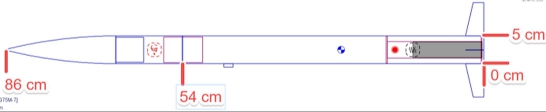
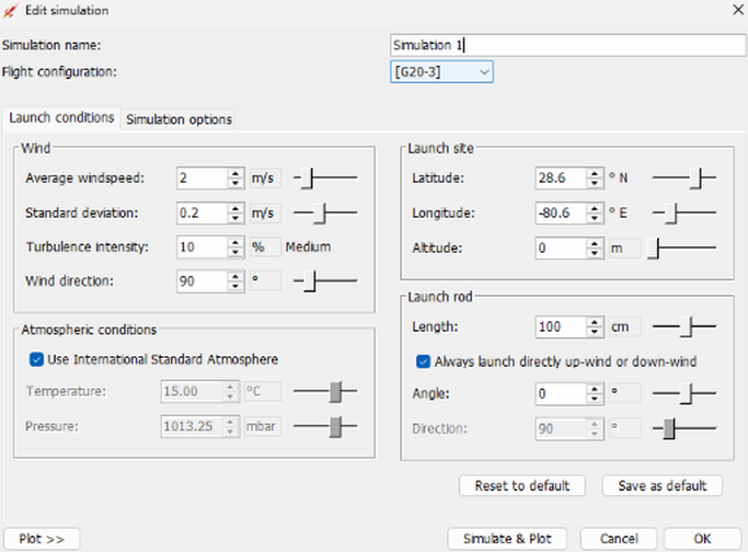
This study used a simulation-based experimental design to compare multiple fin geometries under controlled conditions. OpenRocket Simulation was used to create a model rocket that served as the control for all simulations. The model rocket was loosely based on the dimensions of the LOC Precision Nike Zeus model rocket16. Its length was 86 cm, and its diameter was 5 cm (see Figure 1 for exact dimension specifications). The entire rocket weighed 729 g without any motors. Although based on the Nike Zeus, the simulated model rocket omitted the Nike Zeus’ additional smaller fins, including only the primary base fins. Realistic launch conditions, including wind, launch site, launch rod, and atmosphere specifications, were created in OpenRocket (Appendix B). The independent variable in this study was fin design (Clipped Delta, Fin A, Fin B, and Fin C). The dependent variables were apogee, stability, and maximum velocity. Controlled variables included rocket dimensions, center of gravity, motor type, and material properties.
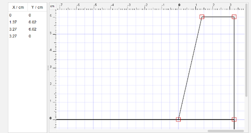
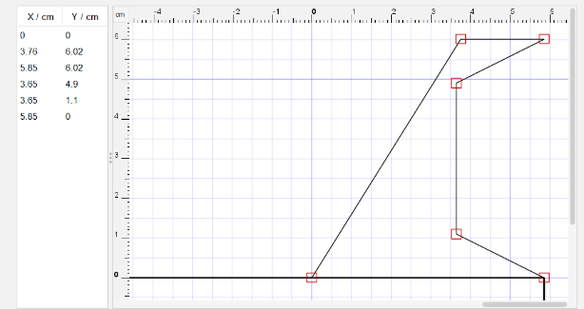
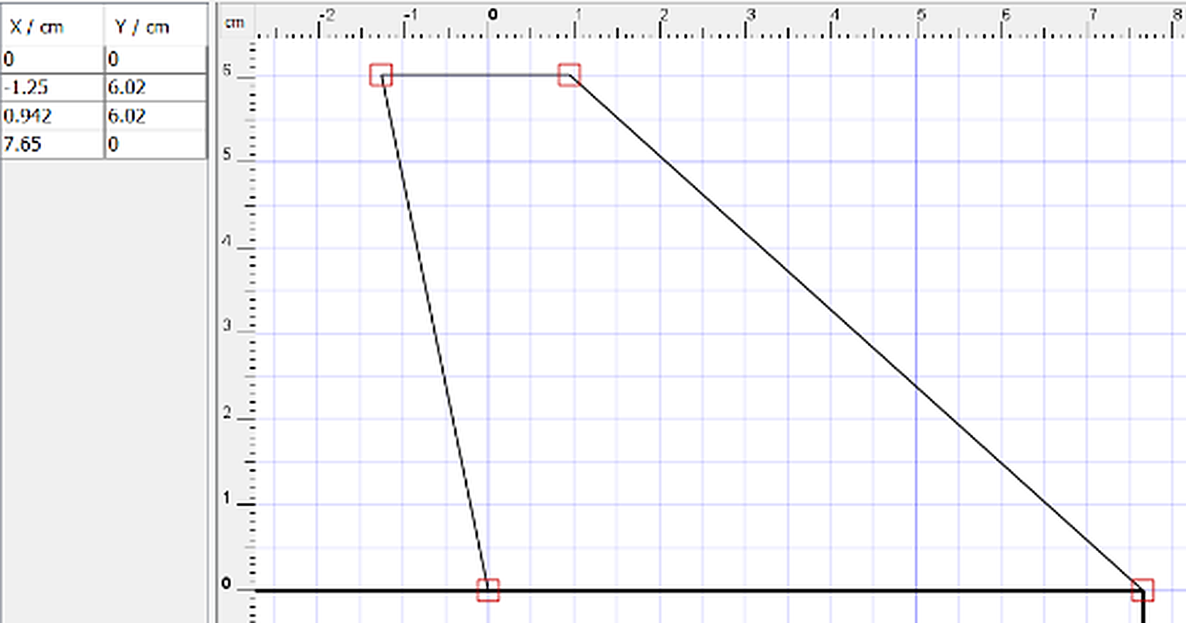
After designing the model rocket, its fins were created. Each fin design was saved as a separate file. To create each fin in OpenRocket, the freeform fin setting was used to model each fin with its specific dimensions (Appendix D, E, F, G). All fins were assigned a mass of 1.29 g, holding fin mass constant across all four designs so that comparative results reflect geometry rather than a mass confound. For the Clipped Delta, the root chord was 3.27 cm, the tip chord was 1.90 cm, the semi-span was 6.02 cm, the leading edge sweep angle was 12 degrees from vertical, and the trailing edge sweep angle was 90 degrees. For Fin C, the root chord was 7.65 cm, the tip chord was 2.19 cm, the semi-span was 6.02 cm, the leading edge sweep angle was -46 degrees, and the trailing edge sweep angle was -56 degrees. For Fin B, the root chord was 5.85 cm, the tip chord was 2.09 cm, the semi-span was 6.02 cm, the leading edge sweep angle was 32 degrees, and the trailing edge sweep angle was 90 degrees. As seen in Appendix F, for the cutout portion in the back of the fin, they entered two coordinate points (3.64, 4.90) and (3.65, 1.10). For Fin A, the Desmos Graphing Calculator was used to construct many tiny edges that formed a curve since OpenRocket cannot construct curves. A 3rd order Bézier Curve was used to create the fin and then split it into about a hundred discrete segments. This was done by defining the Bézier Curve as a parametric function (f(t), g(t)), then inputting t = 0.01, 0.02, 0.03…0.99, 1.00. After that, each individual segment had to be manually inputted into OpenRocket to estimate the curve.
Table 1 below summarizes the key geometric parameters of each fin design alongside the Clipped Delta baseline, allowing the magnitude of each modification to be compared directly.
| Fin | Root Chord (cm) | Tip Chord (cm) | Semi-Span (cm) | LE Sweep (deg) | TE Sweep (deg) | Mass (g) | Modification-Specific Dimensions |
| Clipped Delta (baseline) | 3.27 | 1.90 | 6.02 | 12 | 90 | 1.29 | — |
| Fin A | 3.27 | 1.90 | 6.02 | curved (3rd-order Bézier) | 90 | 1.29 | R(0) = 26.49 cm, R(0.5) = 11.55 cm, R(1) = 8.36 cm |
| Fin B | 5.85 | 2.09 | 6.02 | 32 | 90 | 1.29 | Trailing-edge cutout: points (3.64, 4.90) cm and (3.65, 1.10) cm |
| Fin C | 7.65 | 2.19 | 6.02 | -46 | -56 | 1.29 | — |
The equation of the curve was:
Key Values:
R(0) = 26.49 R(0.5) = 11.55 R(1) = 8.36
Where “t” represents the length of the curve, with t=0 being the beginning of the curve and t=1 being the end of the curve. R(t) represents the radius of the curvature at that point. A higher radius value means a wider, straighter curve, while a lower radius value signifies a sharper, tighter curve.
Trade studies were conducted in OpenRocket to optimize the Clipped Delta, Fin B, and Fin C (Appendix C). Fin A could not be optimized because OpenRocket does not allow fins to have a perfect curve. Constructing multiple curves through Desmos would be unrealistic because each curve required extensive manual construction. All final tests used the optimized fin designs except Fin A. This necessitated the exclusion of Fin A from any accurate comparisons of the fin type performance; Fin A was instead evaluated as a separate, preliminary case study (Table 5) whose results should not be interpreted as evidence of inferiority or superiority relative to the optimized fins.
Each fin was tested with three different motors (G40-4W, G80T-4, and HP-G75M) to provide a more holistic view. The G40-4W weighs 123 g, G80T-4 weighs 128 g, and HP-G75M weighs 131 g. Each motor was picked based on its impulse; G40-4W had a total impulse of 99.0 N-s, G80T-4 had a total impulse of 133.0 N-s, and HP-G75M had a total impulse of 115.2 N-s. The burn times were 2.3, 1.7, and 1.6 seconds. Because OpenRocket simulations are deterministic, meaning there is no variation between multiple identical tests of the same fin, each fin was evaluated under nine distinct launch conditions. The launch conditions were varied by altering the wind speed and launch angle. They tested three types of wind speeds (0 m/s, 2 m/s, 4 m/s) with a constant 10% turbulence and three types of launch angles (-3 degrees, 0 degrees, 3 degrees). In total, they had 27 trials for each fin except Fin A. Because they could not compare Fin A to the other fins, there was no need to run 27 trials for Fin A since they treated it as a separate case study. The center of gravity was held constant across motors within each fin design to eliminate it as an additional variable; center of gravity was not additionally varied as part of the sensitivity analysis because each fin’s CG had already been selected through the trade studies described above, and perturbing it independently would depart from the optimized configuration being evaluated. Wind speed and launch angle were varied instead to characterize how sensitive the performance rankings are to realistic flight-condition uncertainty.
After each simulation, data for apogee, maximum velocity and lateral velocity were collected. This was done by selecting the plot/export option, which displayed all data points for each measurement throughout the flight. The highest point on the graph was then used to determine the highest altitude (apogee), the maximum velocity, and the maximum lateral velocity reached during flight. For the stability caliber, the value calculated by OpenRocket at the instant of launch was recorded, since the static margin is only reported at discrete flight events in OpenRocket’s output and launch represents the most conservative (lowest-margin) point before the rocket clears the launch rod.
Using maximum and lateral velocities, the trajectory angle for each trial was calculated with arcsin(lateral velocity / max velocity), and the absolute value of the angle difference between the trajectory angle and launch angle was calculated to indicate how much the actual path deviated from the ideal path. Because the maximum lateral velocity and maximum velocity used in this calculation may occur at different instants during flight, this quantity is treated as an approximate deviation indicator rather than a direct physical measurement of stability. A larger angle difference indicated lower rocket stability by this approximate measure.
After completing all 81 trials, the average apogee, maximum velocity, and angle difference were calculated for each fin. Using their data, the Normalized Altitude per Impulse Ratio was calculated for each fin using Equation 1:
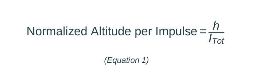
where h is the average apogee of the rocket in meters (m) and ITot is the Total Impulse (N-s).
The primary measure of stability was the angle difference between the launch angle and trajectory angle; the fin with the lowest average angle difference demonstrated the highest stability by producing the least trajectory deviation. A secondary measure of stability was the stability in calibers, with values between 1 and 2 calibers indicating stable flight17. The authors ensured that each fin’s stability caliber fell within this optimal range. Understanding the relationship between angle difference and stability calibers is crucial. A higher stability caliber means the rocket has a greater tendency to resist wind by orienting itself into the wind to maintain a straighter path. However, it also increases the tendency to weathercock, where the rocket over-orients itself into the wind, resulting in a curved flight path18.
Measuring the apogee, angle difference, and maximum velocity provided a comprehensive assessment of each fin’s performance relative to the Clipped Delta. Additionally, using three different motors allowed the authors to observe how each fin modification reacted to increased or decreased thrust.
To test if the simulation’s precision affected the results, a convergence test was performed for each fin to determine the numerical noise floor for the apogee, maximum velocity, and angle difference. Each fin was simulated with the baseline launch conditions (Appendix B) and used the G40-4W motor. Four trials were run for each fin with numerical time steps of 0.1, 0.05, 0.02, and 0.01 s, with 0.01 s being the finest step in OpenRocket. Across all fins, apogee varied by no more than 1 m, maximum velocity by no more than 0.1 m/s, and angle difference by no more than 0.05° (Appendix H). This convergence test establishes that the differences reported between fins are not merely artifacts of OpenRocket’s numerical time-stepping; it does not, on its own, establish that these differences are statistically significant, which is addressed separately below.
Statistical Analysis
Each fin was tested under the same 27 combinations of motor, launch angle, and wind speed, so the resulting trial data form a matched, repeated-measures design across fins rather than independent samples. A Friedman test — the nonparametric analogue of a repeated-measures ANOVA — was used as an omnibus test for each metric (apogee, maximum velocity, and trajectory-launch angle difference) across the three optimized fins (Clipped Delta, Fin B, Fin C); Fin A was excluded, consistent with its treatment as an unoptimized case study throughout this paper. Where the omnibus test was significant, pairwise Wilcoxon signed-rank tests, matched by condition, were used to compare each pair of fins directly, with a Bonferroni correction applied across the three pairwise comparisons per metric. Effect sizes are reported as the matched-pairs rank-biserial correlation. Because OpenRocket’s simulations are deterministic rather than independently sampled, these tests evaluate whether the ranking between fins is consistent across the range of launch conditions tested, rather than whether repeated identical trials would differ by chance; this distinction is discussed further in the Limitations and Improvements section.
Furthermore, the Normalized Altitude per Impulse Ratio was calculated to compare fin performance across all three motors using Equation 1 (Figure 2). Normalized Altitude per Impulse measures how effectively a rocket converts motor impulse into actual apogee. This metric is utilized because total impulse alone does not fully describe flight performance. Van Milligan demonstrated this by showing that two rockets with identical weight and total impulse achieved differing apogees19. Therefore, aerodynamic drag affects how impulse translates into apogee. A higher Normalized Altitude per Impulse means that the rocket flies higher for the same propulsion input, which quantifies overall flight efficiency. This ratio helped determine how effectively each fin converts available motor impulse into altitude.
Results
| Trial | Max Apogee (m) | Max Velocity (m/s) | Lateral Velocity (m/s) | Stability (cal) | Traj.−Launch Angle Diff. (°) | Norm. Alt. per Impulse (s/kg) |
| Clipped Delta — Motor G40-4W | ||||||
| Average | 465.44 | 92.77 | 7.38 | 1.96 | 2.95 | 4.70 |
| Clipped Delta — Motor G80T-4 | ||||||
| Average | 725.56 | 133.89 | 9.1 | 1.92 | 2.57 | 5.46 |
| Clipped Delta — Motor HP-G75M | ||||||
| Average | 623.11 | 120.78 | 8.13 | 1.92 | 2.61 | 5.41 |
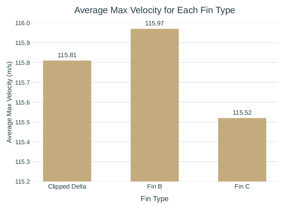
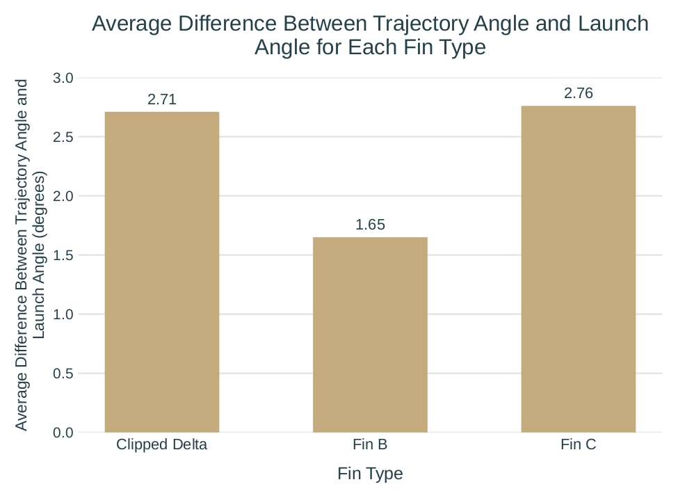
| Total Averages | 604.7 | 115.81 | 8.2 | 1.93 | 2.71 | 5.19 |
| Trial | Max Apogee (m) | Max Velocity (m/s) | Lateral Velocity (m/s) | Stability (cal) | Traj.−Launch Angle Diff. (°) | Norm. Alt. per Impulse (s/kg) |
| Fin B — Motor G40-4W | ||||||
| Average | 468.44 | 92.9 | 5.15 | 1.21 | 1.76 | 4.73 |
| Fin B — Motor G80T-4 | ||||||
| Average | 731.11 | 134 | 6.85 | 1.18 | 1.62 | 5.5 |
| Fin B — Motor HP-G75M | ||||||
| Average | 627.11 | 121 | 6.35 | 1.17 | 1.57 | 5.44 |
| Total Averages | 608.89 | 115.97 | 6.12 | 1.19 | 1.65 | 5.22 |
| Trial | Max Apogee (m) | Max Velocity (m/s) | Lateral Velocity (m/s) | Stability (cal) | Traj.−Launch Angle Diff. (°) | Norm. Alt. per Impulse (s/kg) |
| Fin C — Motor G40-4W | ||||||
| Average | 459.11 | 92.57 | 7.39 | 1.65 | 3.12 | 4.64 |
| Fin C — Motor G80T-4 | ||||||
| Average | 711.78 | 134 | 9.42 | 1.77 | 2.67 | 5.35 |
| Fin C — Motor HP-G75M | ||||||
| Average | 612.7 | 120 | 7.72 | 1.61 | 2.48 | 5.32 |
| Total Averages | 594.56 | 115.52 | 8.18 | 1.68 | 2.76 | 5.1 |
| G40-4W | G80T-4 | HP-G75M | |
| Lateral Velocity (m/s) | 6.91 | 6.92 | 6.95 |
| Trajectory Angle (°) | 4.31 | 2.98 | 3.32 |
| Max Velocity (m/s) | 92 | 133 | 120 |
| Apogee (m) | 455 | 705 | 606 |
| Stability (cal) | 1.76 | 1.75 | 1.74 |
| Normalized Altitude Per Impulse (s/kg) | 4.60 | 5.30 | 5.26 |

Fin A did not perform very well because it was not optimized during testing (Table 5). Since it was the only fin type not optimized, its results are reported as a separate case study, and no comparative or superiority/inferiority claim is drawn from them here.
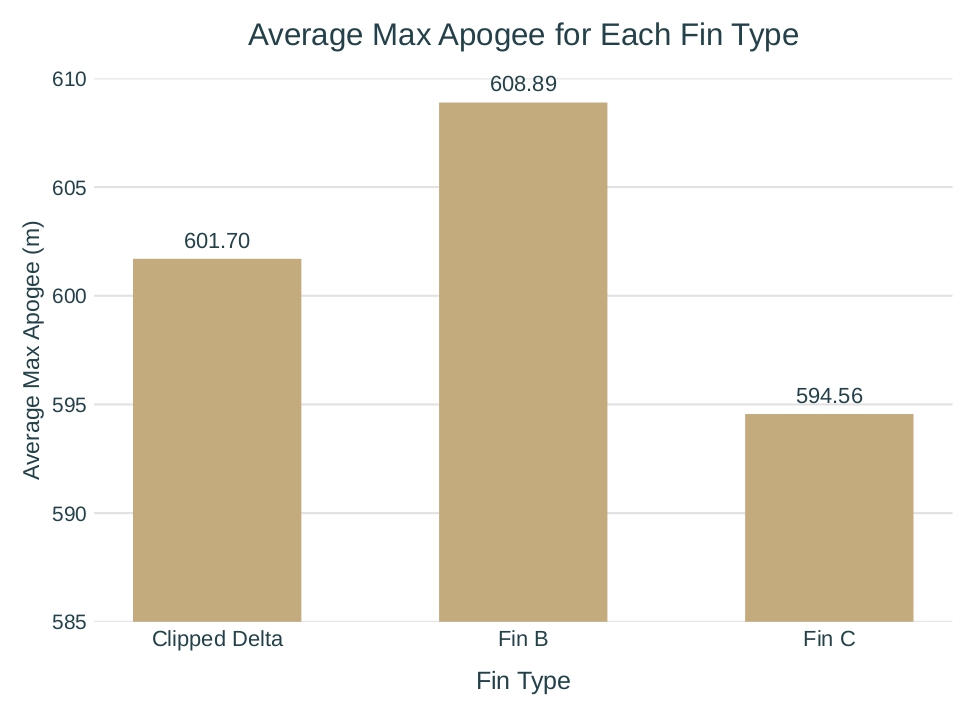
Fin B had the highest apogees for all 3 motors, with an average of 4.19 m, 0.7% greater than the Clipped Delta, and 14.33 m, 2.4% greater than Fin C. It had the highest average max velocities across all 3 motors but was close to both fins with a small difference of less than 1 m/s (Table 3), yet still greater than the 0.1 m/s numerical noise floor (Appendix H). Fin B had the best average angle difference, which was 40.2% lower than Fin C, at 1.11 degrees lower. Additionally, it performed highest in Normalized Altitude per Impulse.
The Clipped Delta Fin ranked second in apogee, maximum velocity, and angle difference across the average of all trials (Table 2). Its average apogee was 10.14 m, or 1.7%, greater than Fin C, which is above the numerical noise floor (Appendix H). However, the angle difference was much worse than Fin B, with an average of 64.2%, or 1.06 degrees, higher than Fin B. Additionally, its Normalized Altitude per Impulse was second compared to other fins.
Fin C had the worst average apogee, average maximum velocity, and average angle difference for all trials (Table 4). The average angle difference was similar to the Clipped Delta Fin, being only 2% lower, which is within the numerical noise floor of 0.05 degrees. Additionally, Fin C had the worst Normalized Altitude per Impulse ratio.
Statistical Significance of Fin Differences
A Friedman omnibus test was run for each metric across the three optimized fins, using all 27 matched trials per fin, followed by Bonferroni-corrected (×3) Wilcoxon signed-rank tests for each pair of fins. Table 6 summarizes the results.
| Metric | Friedman χ² (df=2) | Friedman p | Clipped Delta vs. Fin B (corrected p) | Clipped Delta vs. Fin C (corrected p) | Fin B vs. Fin C (corrected p) |
| Max Apogee (m) | 52.07 | <0.0001 | 0.00002 (sig.) | 0.00002 (sig.) | 0.00002 (sig.) |
| Max Velocity (m/s) | 25.48 | <0.0001 | 0.099 (n.s.) | 0.029 (sig.) | 0.0005 (sig.) |
| Traj.−Launch Angle Diff. (°) | 20.07 | <0.0001 | 0.0014 (sig.) | 1.000 (n.s.) | 0.0001 (sig.) |
All three omnibus Friedman tests were significant (p < 0.0001), indicating that fin type has a detectable, non-random effect on apogee, maximum velocity, and angle difference across the range of launch conditions tested. The pairwise comparisons refine this picture in three ways. First, the apogee ranking reported above (Fin B > Clipped Delta > Fin C) is statistically robust: all three pairwise differences remain significant after correction, with large matched-pairs effect sizes (|r| > 0.98 for all three comparisons). Second, for maximum velocity, the Clipped Delta’s and Fin B’s advantages over Fin C are both significant, but the Fin B vs. Clipped Delta difference — a mean gap of only about 0.16 m/s — does not reach significance after correction (corrected p = 0.099); the claim that Fin B has the single highest maximum velocity of the three fins should therefore be treated as suggestive rather than statistically confirmed. Third, for the angle-difference stability measure, Fin B’s advantage over both other fins is significant, while the Clipped Delta and Fin C are not significantly different from each other (corrected p = 1.000), which is consistent with that particular comparison falling within the numerical noise floor already noted in the Methods.
An important interpretive caveat applies to all of the above: because OpenRocket’s simulations are deterministic, the 27 trials per fin are not independent random samples of a single repeated scenario, but 27 different, deliberately varied launch conditions (wind speed and launch angle) run once each. These tests therefore establish that the fin ranking is consistent across the range of conditions simulated here, not that the same differences would necessarily survive real-world sources of variability — manufacturing tolerances, atmospheric variation beyond what was modeled, or measurement noise in physical flight testing. This distinction is revisited in the Limitations and Improvements section.
Discussion
The Clipped Delta fin performed second in all measurements relative to the other fins. Fin B performed best overall, while Fin C performed the worst. The results for Fin A cannot be properly interpreted because it was not optimized.
The hypothesis was that Fin A would be the only modification to improve the Clipped Delta because its shape was expected to reduce aerodynamic drag by allowing smoother airflow. However, since it was the only fin type not optimized, an accurate comparison or extrapolation to the other fins cannot be made.
Fin B consistently performed best in all three categories—apogee, maximum velocity, and angle difference—especially when considering the Normalized Altitude per Impulse; a higher ratio indicates more efficient fin designs. These differences (Table 3) from the Clipped Delta and Fin C are above the numerical noise floor, revealing that they exceed the simulation’s time-step precision (Appendix H) and are not affected by the simulation’s numerical time step; this does not by itself establish that the differences exceed the resolution of OpenRocket’s underlying aerodynamic model, a separate limitation addressed below. The nonparametric testing in Table 6 supports Fin B’s apogee and angle-difference advantages as statistically robust across the conditions tested; the one exception is maximum velocity, where Fin B’s edge over the Clipped Delta specifically does not reach significance after correction, so that particular comparison is better described as suggestive than confirmed. Contrary to the hypothesis, the unconventional shape of the fins may have increased the rocket’s performance. Previous research has shown that modifications to the trailing edge can alter airflow behavior and pressure distribution over a surface, leading to changes in aerodynamic performance20. Because the trailing edge plays an important role in how airflow leaves the fin, altering its geometry may affect the forces acting on the rocket during flight. However, since airflow patterns were not directly measured with CFD analysis or flow visualization, the exact aerodynamic reason for Fin B’s strong performance cannot be fully ascertained.
As hypothesized, Fin C performed worst in all three categories. The results (Table 4) showed differences from Fin B and the Clipped Delta that were above the numerical noise floor (Appendix H) except for the average angle difference, which was within the numerical noise floor when compared to the Clipped Delta and should be interpreted with caution. This indicates that almost all of these differences are unlikely to be affected by the simulation’s time step. A possible explanation for these results is that the forward-swept shape influences vortex formation and airflow, which can negatively impact aerodynamic stability and lift21. Furthermore, the forward-swept configuration has been reported to outperform the backward-swept configuration at high angles of attack22.This would decrease stability and increase drag, reducing apogee and maximum velocity. Fin C’s performance may be related to its altered sweep geometry; however, this study relied on OpenRocket and lacked extensive CFD analysis, flow visualization, or direct measurements of aerodynamic forces that would have confirmed the mechanisms responsible for the model rocket’s performance. The results for Fin C are a finding of this study; any explanation related to vortex behavior or airflow patterns should be considered a hypothesis requiring further investigation, not a confirmed mechanism.
Limitations & Improvements
Throughout this study, the researchers used OpenRocket software to conduct their experiments. Since OpenRocket uses Barrowman equations when calculating CP and stability, it automatically assumes that the fins tested have flat, symmetrical surfaces, which could invalidate some of their data. While numerical precision testing established the lower bound of the simulation’s precision with respect to the time step, this does not include all potential sources of uncertainty. The difference in apogee could very well be due to OpenRocket’s simulation errors or its aerodynamic modeling assumptions rather than any intrinsic performance differences of the fins themselves.
Relatedly, this study did not independently validate OpenRocket’s Barrowman-based aerodynamic model against real flight data for geometric changes as small as the ones tested here (a sub-2% change in apogee). Peer-reviewed comparisons between OpenRocket and instrumented real-world flights have found that OpenRocket’s predictions can diverge from measured flight data by several degrees in pitch angle and several percent in apogee, with the divergence generally growing as the rocket approaches apogee23. This suggests that OpenRocket’s resolution may not be fine enough to confidently distinguish performance differences as small as those reported in this study, and this is acknowledged here as a key limitation rather than something the current dataset can rule out. A dedicated flight-validation or accuracy study focused specifically on small fin-geometry perturbations is proposed as future work before these rankings are treated as conclusive.
This study includes a formal nonparametric significance test — a Friedman omnibus test followed by Bonferroni-corrected Wilcoxon signed-rank pairwise comparisons (see Results, Table 6). An important caveat still applies to how these results should be read: because OpenRocket’s simulations are deterministic, the 27 trials per fin are 27 different, deliberately varied launch conditions rather than independent repeated measurements of one scenario. The significance tests therefore show that each fin’s ranking holds consistently across the launch conditions simulated here; they do not, on their own, demonstrate that the same differences would survive real-world manufacturing tolerances, atmospheric variability beyond what was modeled, or measurement noise during physical flight testing. Confirming that is a task for future flight validation, not for additional simulation-based statistics.
Additionally, this study does not include physical launch validation, which may affect real-world applicability. While theoretically accurate, OpenRocket inevitably does not account for unpredictable variations in how fins react to real flight conditions. Finally, Fin A could not be optimized because OpenRocket does not allow fins to have a perfect curve. Although the authors were able to approximate a curve using Bézier functions, optimizing multiple curved variations was impractical. Since Fin A could not be optimized, its results could not be accurately compared to the other optimized fins, making Fin A’s results functionally inconclusive.
Several improvements could strengthen future studies. In future iterations of this study, Fin A could be optimized like the other fins. With this, the results produced by the optimized Fin A may prove the fin to be more efficient than what was previously gathered from their data. To further ascertain the reasons for the differences in fin performance beyond speculation, an airflow simulation—like ANSYS or OpenFOAM—can be used to observe the airflow around each fin, potentially providing insights into why certain fins performed better than others.
Furthermore, additional studies could be conducted to build upon the success of Fin B by creating variations of it—such as varying the size of the cutouts—to find the optimal form. Future studies for determining the best fin could also consider manufacturability and cost in addition to performance, providing a more realistic view.
Their research suggests there may be more aerodynamically efficient designs than the Clipped Delta Fin. Compared to the Clipped Delta, Fin B improved apogee, maximum velocity, and the angle-difference measure of stability. These modifications could be tested in the model rocketry industry, as well as the broader rocketry industry, to increase rocket performance and efficiency, with the caveats on statistical robustness, simulation validation, and stability-metric reconciliation described above kept firmly in view before generalizing these findings.
Conclusion
Within the OpenRocket conditions modeled, Fin B produced a slightly higher simulated apogee and a lower trajectory-deviation indicator than the Clipped Delta baseline, while Fin C generally performed below it and the unoptimized Fin A was treated as preliminary. Because these differences are small, the simulations are deterministic rather than independent physical replicates, and OpenRocket may not resolve geometry changes this subtle, these results should be read as simulation-based indications rather than validated real-world findings; physical flight testing and CFD analysis are needed before the fin rankings can be treated as conclusive. The study’s main contribution is methodological: a low-cost, accessible workflow for probing fin-geometry effects that can guide more resource-intensive validation.
Appendix
The Appendix is necessary because it includes data from the launch conditions and trade studies that were used to find the optimal fin design for each modification. These detailed results support the design selection process but are not central to the main hypothesis. This information is included in the Appendix to maintain readability and keep the main manuscript focused on the fin shape modifications and their outcomes.
Appendix A. Units of Measurement
| Quantity | SI Unit | U.S. Customary Unit |
| Apogee | m | in |
| Center of Gravity | cm | in |
| Center of Pressure | cm | in |
| Stability | cal | cal |
| Velocity | m/s | in/s |
| Total Impulse | N*s | lb.*in/s |
| Normalized Altitude per Impulse | s/kg | lbs/kg |
Appendix B. Launch Conditions
Appendix C. Trade Studies for Optimal Sweep Angle and Centre of Gravity
The results for the optimal sweep angle and center of gravity of the Clipped Delta, Fin B, and Fin C. Results were collected through OpenRocket Simulation. Highlighted rows are the chosen optimal angles and centers of gravity. The center of gravity for each fin was measured from the base of the rocket. For the angle trade studies, thirteen different sweep angles were tested per fin using the G40-4W motor to identify the angle that produced the best combination of max apogee, max velocity, and stability (lowest lateral velocity together with a caliber value between 1 and 2). The optimal angle for the Clipped Delta was 78 degrees, for Fin B was 58 degrees, and for Fin C was 102 degrees. For brevity, the angle trade-study tables below show the endpoints of the tested range and the selected optimum; the complete thirteen-point sweeps for all fins are provided in the supplementary materials. Eleven different centers of gravity were then tested per fin at each optimal angle; all three fins converged on an optimal center of gravity of 60.2 cm. Because all three fins converged on the same optimal center of gravity, only the Clipped Delta center-of-gravity trade study is shown as a representative case; the Fin B and Fin C centre-of-gravity trade studies produced the same 60.2 cm optimum and are available in the supplementary materials. Fin A’s optimal angle and center of gravity could not be tested because generating and optimizing a distinct Bézier-curve fin file for each trial candidate was impractical given OpenRocket’s lack of native curve support.
Clipped Delta — Angle Trade Study (G40-4W motor)
| Angle (°) | Max Apogee (m) | Max Velocity (m/s) | Lateral Velocity (m/s) | Stability (cal) |
| 30 | 456 | 92.3 | 7 | 1.65 |
| 78 | 468 | 92.9 | 5.76 | 1.71 |
Fin B — Angle Trade Study (G40-4W motor)
| Angle (°) | Max Apogee (m) | Max Velocity (m/s) | Lateral Velocity (m/s) | Stability (cal) |
| 30 | 460 | 92.5 | 5.62 | 1.37 |
| 58 | 469 | 92.9 | 4.49 | 1.05 |
| 78 | 48.2 | 55.6 | 15.65 | -0.443 |
Note: The sharp apogee and velocity collapse at 70–78°, together with the caliber value turning negative at 78°, indicates the rocket became aerodynamically unstable (center of pressure ahead of center of gravity) at those extreme sweep angles rather than a simulation artifact; these angles were correctly excluded from consideration as the optimum.
Fin C — Angle Trade Study (G40-4W motor)
| Angle (°) | Max Apogee (m) | Max Velocity (m/s) | Stability (cal) | Lateral Velocity (m/s) |
| 102 | 461 | 92.6 | 1.79 | 6.72 |
| 150 | 450 | 92 | 1.29 | 5.99 |
Center of Gravity Trade Study (representative: Clipped Delta, optimal angle, G40-4W motor)
| CG (cm) | Max Apogee (m) | Max Velocity (m/s) | Lateral Velocity (m/s) | Stability (cal) |
| 11.5 | 467 | 92.9 | 7 | 11.7 |
| 16.4 | 467 | 92.9 | 7.36 | 10.7 |
| 21.2 | 466 | 92.9 | 7.69 | 9.93 |
| 26.1 | 466 | 92.9 | 7.94 | 8.79 |
| 31 | 466 | 92.9 | 8.2 | 7.81 |
| 35.9 | 466 | 92.9 | 8.34 | 6.84 |
| 40.7 | 466 | 92.9 | 7.36 | 5.86 |
| 45.6 | 466 | 92.9 | 8.12 | 4.89 |
| 50.5 | 466 | 92.9 | 7.67 | 2.93 |
| 55.4 | 466 | 92.9 | 7.57 | 2.3 |
| 60.2 | 468 | 92.9 | 7.07 | 1.96 |
Appendix D. Clipped Delta Freeform Measurements
Appendix E. Fin A freeform Measurement

Appendix F | Fin B Freeform Measurements
Appendix G. Fin C Freeform Measurements
Appendix H. OpenRocket Statistical Precision Tests.
The data for each fin from the convergence analysis of the numerical precision of OpenRocket with respect to the time step, using the G40-4W motor and baseline launch conditions (Appendix B). This shows the numerical noise floor of the apogee, maximum velocity, and angle difference; it characterizes the simulation’s numerical precision only, and is a distinct question from the statistical significance of the differences between fins (see Limitations & Improvements).
Clipped Delta (G40-4W)
| Time Step (s) | Apogee (m) | Max Velocity (m/s) | Angle Difference (°) |
| 0.1 | 467 | 92.9 | 4.49 |
| 0.05 | 467 | 92.9 | 4.51 |
| 0.02 | 466 | 92.9 | 4.52 |
| 0.01 | 466 | 92.9 | 4.51 |
Fin B (G40-4W)
| Time Step (s) | Apogee (m) | Max Velocity (m/s) | Angle Difference (°) |
| 0.1 | 470 | 93 | 2.6 |
| 0.05 | 469 | 92.9 | 2.6 |
| 0.02 | 469 | 92.9 | 2.6 |
| 0.01 | 469 | 92.9 | 2.6 |
Fin C (G40-4W)
| Time Step (s) | Apogee (m) | Max Velocity (m/s) | Angle Difference (°) |
| 0.1 | 460 | 92.6 | 4.63 |
| 0.05 | 460 | 92.6 | 4.65 |
| 0.02 | 460 | 92.6 | 4.68 |
| 0.01 | 460 | 92.6 | 4.67 |
Supplementary Material
References
- NASA. Rocket history – 20th century and beyond. 2025, http://www.grc.nasa.gov/www/k-12/rocket/BottleRocket/20thBeyond.htm. [↩]
- N. Hall. Model rockets and real rockets. 2023, https://www1.grc.nasa.gov/beginners-guide-to-aeronautics/model-rockets-and-real-rockets/. [↩]
- LOC Precision. Buy high power model rocket kits – Rocketry kits online. 2025, https://locprecision.com/collections/rocket-kits. [↩]
- J. Daecher. Model rockets fins purpose. 2025, https://austinrockets.org/model-rockets-fins-purpose/. [↩]
- Cadence CFD. Exploring the aerodynamics of symmetrical airfoil. 2025, https://resources.system-analysis.cadence.com/blog/msa2022-exploring-the-aerodynamics-of-symmetrical-airfoil. [↩]
- V. Dixit, G. Goplani, A. Aggarwal, H. Shukla. Fin design and aerodynamics in high-speed missile and rocket systems. Mechanics and Materials Science of Biological Materials. Vol. 1, pg. 265–271, 2025, https://doi.org/10.1007/978-981-96-5366-9_15. [↩]
- B. Matthew, B. S. Kotapati, T. Akhil, R. K. Sirikonda. Aerodynamic investigation of flow parameters on trapezoidal fin. AIP Conference Proceedings. Vol. 2962, Art. 020052, 2024, https://doi.org/10.1063/5.0193299. [↩]
- Y. Baloda, A. Jaiswal, X. He, A. Datye. Theoretical and experimental performance evaluation of shark-caved, sounder, and trapezoidal fins. Proceedings of the National Conference on Undergraduate Research (NCUR) 2020. University of Montana, Bozeman, pg. 1–8, 2020, https://libjournals.unca.edu/ncur/wp-content/uploads/2020/12/3189-Baloda-Yogesh-FINAL-2.pdf. [↩]
- V. Nagaraj. The effect of various fin designs on the stability, maximum height, and drag of model rockets to maximize efficiency. Journal of High School Research. Vol. 2, Art. 91325003, 2025, https://doi.org/10.70671/5wkby353. [↩]
- M. H. S. bin Noor Azman. A study on aerodynamic shape of fin of model rocket using computational fluid dynamics (CFD). Research Progress in Mechanical and Manufacturing Engineering. Vol. 2, No. 2, 2022, https://publisher.uthm.edu.my/periodicals/index.php/rpmme/article/view/4866. [↩]
- A. Datye. Fin optimization for enhanced flight performance of an experimental rocket. Proceedings of the National Conference on Undergraduate Research (NCUR) 2018. University of Central Oklahoma, Edmond, Oklahoma, 2018, https://libjournals.unca.edu/ncur/wp-content/uploads/2021/03/2640-Datye-Athary-FINAL-m.pdf. [↩]
- D. Fernández-Gutiérrez, W. M. van Rees. Effect of leading-edge curvature actuation on flapping fin performance. Article, August 2021, https://www.researchgate.net/publication/352918399_Effect_of_leading-edge_curvature_actuation_on_flapping_fin_performance [↩]
- A. Broatch, J. García-Tíscar, A. Felgueroso, M. Chávez-Modena, L. M. González, E. Valero. Numerical and experimental analysis of rounded fins for high speed air-cooled heat exchangers. International Journal of Heat and Mass Transfer. Vol. 201, Art. 123575, 2023, https://doi.org/10.1016/j.ijheatmasstransfer.2022.123575. [↩]
- J. Ackeret. Experiments on airfoils with trailing edge cut away. Report, September 1927, University of North Texas Libraries Digital Library, https://digital.library.unt.edu/ark:/67531/metadc65246/. [↩]
- Y. Kishi, R. Yashiro, M. Kanazaki. Low-boom design for supersonic transport with canard and forward-swept wings using equivalent area design method. Aerospace. Vol. 10, No. 8, Art. 717, 2023, https://doi.org/10.3390/aerospace10080717. [↩]
- Apogee Components. Nike Zeus. 2025, https://www.apogeerockets.com/Model-Rocket-Kits/Skill-Level-3-Model-Rocket-Kits/Nike-Zeus. [↩]
- A. Hamid, Z. Salleh, M. Muhammad, K. Kamaludin, M. Sujana, M. Khamis. The effect of different designs of fins and nose cones towards the stability and performance of a sugar rocket. 2022, https://www.tuengr.com/V13/13A13J.pdf. [↩]
- A. Posta, A. Monk, A. Durollet, O. Martin, S. Bruton, J. Kim. Improved attitude stabilisation system augmented sounding rocket design, integration, verification & launch. Procedia Computer Science. 2024, https://www.sciencedirect.com/science/article/pii/S2405896324012515. [↩]
- T. Van Milligan. Apogee motors make models fly higher. Apogee Rockets Technical Publication. No. 1, 2009, https://www.apogeerockets.com/Technical_Publication_1. [↩]
- L. Ethiraj, S. N. Pillai. Effect of trailing-edge modification over aerodynamic characteristics of NACA 0020 airfoil. Wind and Structures, Vol. 33, No. 6, pg. 463-470, 2021, https://doi.org/10.12989/was.2021.33.6.463. [↩]
- M. Kanazaki, N. Setoguchi. Characteristics of vortices around the forward swept wing at low speeds/high angles of attack. Aerospace, Vol. 10, No. 9, Art. 790, 2023, https://doi.org/10.3390/aerospace10090790. [↩]
- F. Lundvall, W. Yachnin, J. Perroud, K.-D. Läpple. Forward-swept wings. Proceedings of the 4th TMAL02 Expert Conference 2019, Linköping University, 2019, https://wcc.ep.liu.se/index.php/TMAL02/article/download/548/462/635. [↩]
- A. N. Yilmaz, M. Cihan. Modeling-simulation of pre-apogee trajectories and stability for low altitude unguided sounding rockets. Journal of Aeronautics and Space Technologies, Vol. 17, Special Issue, pg. 65–91, 2024. [↩]