Abstract
Traversing the terrains of other planets poses challenges to rovers because traditional wheels maintain a fixed geometry, forcing a compromise between maneuverability on hard surfaces and flotation on soft surfaces. This project aimed to design an autonomous, reconfigurable wheel that expands its width via an AI-powered, vision-integrated pneumatic system to improve traction on soft and irregular terrain. The wheel was designed using Computer-Aided Design (CAD), and its structural integrity was studied through Finite Element Analysis (FEA) to ensure load-bearing capacity during expansion. A Vision Transformer (ViT) was developed and trained on a custom dataset of various landscapes (sand, rocky terrain, gravel). The model’s performance was evaluated using an accuracy and loss vs. epoch graph.The FEA results suggested that the wheel maintains structural stability even at maximum lateral extension. Although the machine learning model achieved near-perfect validation accuracy, demonstrating the ability to differentiate between terrain types in real-time, analysis of a greater number of images is required to further validate this model. The mathematical analysis suggested that A.T.L.A.S. decreases wheel sinkage in Martian dunes by 35.2% and has a Safety Factor of 1.414, which is the current industry standard for aerospace engineering. The results of this study suggest that integration of computer vision and a pneumatic pump allows for real-time mechanical adaptation of the wheel to terrain. By increasing the contact patch on demand, the system prevents “sinkage” in soft environments like Martian dunes without the need for the rover to permanently carry the bulk of wide tires. When implemented on rovers, this technology may offer a novel solution for both planetary exploration and terrestrial mobility. This study provides preliminary proof-of-concept. Further model optimization and validation are needed in future studies.
Introduction
Rovers are widely used for space exploration as well as on Earth to explore difficult-to-access areas. The exploration of extreme environments, such as the Martian surface or disaster-stricken terrestrial zones, requires a delicate balance between the rover’s maneuverability and flotation. Current planetary rover designs, like those seen on the Curiosity and Perseverance rovers, utilize rigid, fixed-geometry wheels that are susceptible to “sinkage” in soft regolith, a phenomenon known as terramechanics failure. On May 1, 2009, while riding on the Home Plate of Mars, a wheel of the Spirit rover became stuck in soft soil, and in May 2011, after more than a thousand attempts to recover the rover, its mission was formally discontinued1.
This experience demonstrated the importance of wheels in rovers’ mobility and stimulated research on various wheel designs. The existing literature and engineering precedents have primarily focused on variable-diameterwheels in which a wheel is expanded vertically. For example, research into “transformable origami wheels” or “expandable diameter rims” showed that a vehicle may increase its ground clearance or speed by changing the wheel’s height2,3,4. While effective for overcoming vertical obstacles, increasing the diameter does not significantly improve the lateral stability or the distribution of ground pressure as effectively as increasing the width5,6. The wheel’s mobility has been extensively studied, and various models have been developed to support the new research on improved wheel designs.
Two validated and widely used models include the Bekker model7 and Wong and Reece’s model8. Both of them are semiempirical terramechanics models, which created a foundation for the development of modern models. Recent research on wheel mobility has led to the development of dynamic frameworks and computational techniques to gain deeper insights into wheel-terrain interactions. For example, Tran et al., developed a two-dimensional model of the vehicle–terrain interaction to study the mobility of a skid-steering wheeled unmanned ground vehicle on a flat surface9,10. Even though this model considered soil deformations and reaction forces, it could not be directly fit into other vehicles and rovers. Another research group developed a model that captures three-dimensional stress distributions and side-wall bulldozing effects to understand a wheel’s mobility in the soft soil and simulate the off-road mobility of robots11. This model combined the current understanding of the terramechanics and kinematics of the wheel to describe the forces soil exerts on the wheel and how the stress distributes along the interface between the wheel and the terrain. Jia et al., used this model to study the shear stresses underneath the wheel and the influence of grousers, and validated it with both a single wheel and whole vehicles11. Based on the elastoplasticity theory, Azimi et al., developed a velocity-field-driven continuum model, which extended the Bekker and Wong-Reece’s models to derive slip-sinkage and semi-elliptical stress distributions under varying slip rates12. The researchers proposed this model to analyze and simulate mobility of rovers on various terrains12. Modern models, discrete and finite element methods to model soil grain interactions, energy dissipation, and complex multi-grouser contact dynamics on surfaces with varying texture13,14,15, the challenges of soil-wheel interactions and limitations of transformable wheel designs have been reviewed in detail elsewhere16.
The key limitations of vertically expandable wheels include the following. Their mechanical complexity due to the incorporation of active, variable-diameter mechanisms increases the number of actuators, joints, and sensors, thereby creating new failure modes in harsh, unmaintainable environments. Another limitation is the material fatigue and degradation, which occurs due to the repeated, intense deformation caused by traversing sharp, embedded rocks and results in reduced performance. Expanding, airless, or mesh-based wheel designs are difficult to scale to accommodate the high weight of larger, manned pressurized rovers, while increasing load often results in uncontrollable stress on the wheel’s internal components, such as spokes or loops. Rovers equipped with complex, compliant wheels are often restricted to lower speeds, as high-speed operation could exacerbate structural degradation, requiring astronauts to spend more time traveling between locations, thus reducing the rover’s speed and efficiency. Lunar or Martian dust can infiltrate the expanding mechanism, causing the joints of a variable-diameter system to lock. Additionally, extreme thermal variations and high radiation can cause elastomers traditionally used as flexible materials to break down, necessitating the use of specialized, often fragile, metal alloys, while advanced mesh wheels can suffer from punctures or tears, as experienced by the Curiosity rover, whose mission was to explore the Gale Crater on Mars17.
Therefore, to enable the next era of autonomous extraterrestrial exploration, particularly in high-risk zones (like the surface of Ryugu or soft sediment on Mars) and on surfaces with variable conditions, there is an urgent need for research into different expansion methods. As such, research into alternative modes of wheel expansion and contraction is critical because current solutions are inherently unsuited for the variable terrains and the extreme conditions of extraterrestrial bodies.
Consequently, the objective of this research was to design an autonomous, reconfigurable wheel capable of lateral expansion to improve traction on soft and irregular terrains. Review of earlier studies attempting to develop fluidic and pneumatic soft actuators, such as fluid-driven elastomers, and evaluating how they can replace heavy, rigid electric motors and be tailored for space exploration18 motivated the current study to design a balloon-like bladder for the lateral expansion of the wheel. A recent comprehensive review of artificial intelligence algorithms for rovers’ localization, perception, and path planning based on 320 papers available in IEEE Xplore, Web of Science, and Scopus19 served as a further motivation to support the wheel’s design with an AI-driven terrain recognition algorithm. This project had five engineering goals: Design a laterally expandable wheel system in CAD software; Design a balloon-like bladder that will be inflated by a pneumatic pump system and can survive harsh space conditions; Assess the wheel system’s load capabilities using FEA software; Develop an AI-powered image detection algorithm that can assess terrain qualities and make an automatic decision to laterally expand or contract the wheel; and Conduct mathematical analysis to verify the wheel’s feasibility and the technical functionality of the new wheel design.
Traditional wheels maintain a fixed geometry, forcing a compromise between maneuverability on hard surfaces and sinkage on soft surfaces. By introducing a shift from vertical to lateral wheel expansion, this project aimed to develop a wheel that expands its width by half the diameter via an AI-powered vision-integrated pneumatic system. By expanding the wheel’s width by half the diameter, the contact surface area was theoretically expected to increase by approximately 50%, drastically reducing the pressure exerted on the surface. Unlike diameter-based vertical expansion, width expansion was expected to lower the vehicle’s center of gravity and increase the “contact patch” without requiring more vertical space in a launch fairing or chassis. Furthermore, while traditional expanding wheels are manually operated or passive, this project aimed at integrating a real-time terrain classification via a Vision Transformer (ViT). By introducing an AI-operated pneumatic pump into the wheel’s concept, this project intended to design a closed-loop system where the mechanical “body” of the rover reacts autonomously to the “vision” of the AI algorithm, a synergy that represents a novel approach to autonomous planetary locomotion. Furthermore, the project aimed at selecting materials for the wheel so that they are capable of resisting harsh conditions on Mars while retaining the technical functionality of the wheel. Finally, the mathematical analysis was performed to estimate the feasibility of the new wheel’s design, accepting the limitations posed by logistical and resource limitations.
Design and Simulation Methodology
The wheel was designed using Computer-Aided Design (CAD). The structural integrity was validated through Finite Element Analysis (FEA) to ensure load-bearing capacity during expansion.
CAD was performed using OnShape software V1.211 (PTC Inc.).
For FEA, a free version of SimScale v2026-February software was used. The mesh was a 3D unstructured 2nd order mesh composed of 215,554 tetrahedra and 459,107 triangles. Since the mesh was unstructured, the element size varied. Matrix inversion in the FEA was performed by the Chronos Algebraic Multigrid solver library. The convergence criteria were defined by a built-in relative residual force tolerance threshold of 1.0 x 10⁻⁶. The simulation converged within 147 iterations, with a normalized residual of 5.44 x 10⁻⁷. Each spoke was treated as a cantilevered beam that was fixed at one end to the rim of the wheel, and the 150 N UDL was applied to each spoke individually. It has been assumed that each spoke withstands the load of 150 N UDL based on the reported by Rankin et al.20 average pressure load on a spoke in a similarly designed Martian rover wheel of 50 kPa and an estimated surface area of each spoke of 3.08 x 10⁻³ m2 (5 x 104 Pa x 3.08 x 10-3 m2 = 150 N).
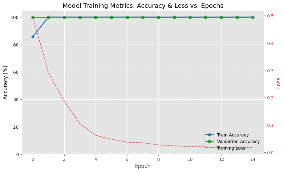
To develop an AI algorithm, Vision Transformer (ViT) was trained on a custom dataset of various landscapes (sand, rock, gravel). The ViT model was trained and tested with a 85/15 split, meaning 85% of images were used to train the model and 15% were used to validate it. The model was trained on 15 epochs, and a validation was conducted after each epoch to gauge the accuracy and loss in each epoch. The model’s performance was further evaluated using the accuracy and loss vs. epoch graph. Mathematical analysis was performed to evaluate the feasibility and technical quality of the new wheel.
The microcontroller was created using Raspberry Pi 5 and Raspberry Pi AI hat+ module (for AI inference). The camera module was composed of a Raspberry Pi Camera module 3 for terrain visualization. The camera was used as follows: after the model was trained and an accuracy and loss vs epoch graph was constructed based on the curated set of images, the model was uploaded to the Raspberry Pi 5 and made compatible with the Raspberry Pi camera module 3. The camera was then used to capture real-world images of various terrains (e.g., a gravel and sand testbed) to qualitatively assess the model’s functionality.
All materials were obtained on Amazon. Images of different terrains were obtained from publicly available sources searchable by Google.
Results
CAD & Assembly of the Wheel
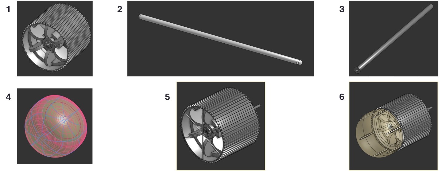
The wheel was designed and composed of the following components (Figure 1):
Main wheel: A model of the wheel, created in OnShape. 16 “Diameter; 12.8” Width.
Laterally expanding spoke: Solid, revolving structure connected by a 90-degree spring hatch that forces it into a closed position (see 5). 6 ribs are used on the final wheel assembly (see 5 or 6). Each spoke was treated like a cantilevered beam. 0.2 “Diameter; 7.93” Length.
Axle: Hollow tube around which the wheel revolves. Hollow to let air from the pneumatic system inflate the balloon-like bladder. 0.624” Diameter; 19.3 “Length; 0.3” hollow tube diameter.
Balloon-like bladder: 1800 cubic-inch inflatable structure. Causes the ribs to expand when inflated, which increases the wheel’s width. Made transparent in the rendered model for visibility.
Contracted assembly: The full assembly (bladder not shown for visual purposes) when the bladder is deflated, and the ribs are contracted.
Expanded assembly: The full assembly when the bladder is inflated and the ribs are expanded outward.
Design of the Balloon-like Bladder
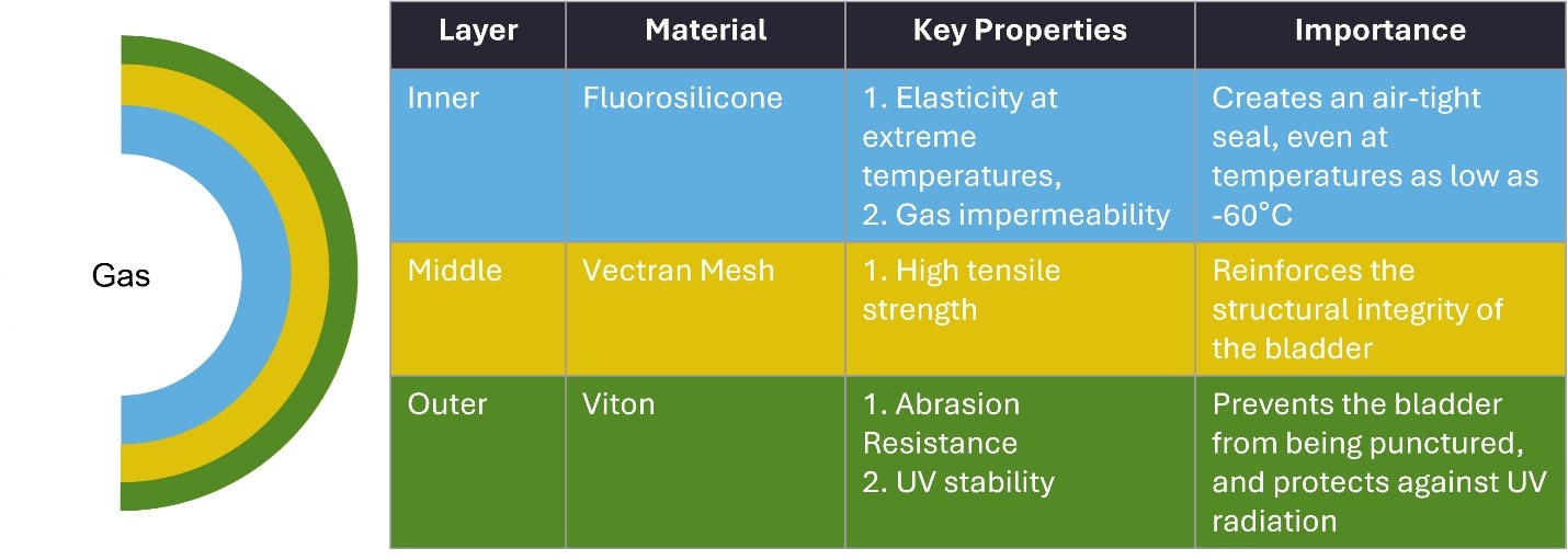
The balloon-like bladder was designed to contain three layers, each made of a different material (Figure 2). Fluorosilicone was selected for the first, internal layer interfacing with the gas when the balloon is expanded, due to its elasticity at extreme temperatures and gas impermeability, which is important to create an air-tight seal at extreme temperatures21. Vectran Mesh was selected for the second, medium layer of the balloon due to its high tensile strength22, which is important to reinforce the structural integrity of the bladder. Viton was selected for the outer layer of the bladder due to its resistance to abrasion and stability under UV irradiation23. This layer would prevent the bladder from being punctured or damaged by the UV radiation. These materials for the balloon-like bladder were selected based on their known properties21,22,23 that would preserve the structural integrity of the balloon when the wheel is in its contracted assembly and in expanded assembly. According to NASA, the median surface temperature on Mars is -65 °C, but it may fluctuate between -153 °C and +20 °C depending on the location and time24. The radiation range is from 0.076 Gy to 0.25 Gy per year25. All selected materials would tolerate the radiation because the lowest radiation they can withstand is 1 x 10⁴ Gy26,27,28, which is way above the typical annual range on Mars. However, temperature tolerability varies between these materials. For example, Vectran mesh has the widest operational range compared to fluorosilicone and Viton because it can tolerate temperatures between -130 °C and + 200 °C26. Thus, Vectran is the most optimal material because it operates within the widest temperature range. Fluorosilicone’s temperature range is from -60 °C to +200 °C29, and that of the Viton is -20 °C to +204 °C30; therefore, these materials can tolerate temperatures on Mars except for when it goes down below -60 °C and -20 °C, for fluorosilicone and Viton, respectively.
Further validation of this design through experimental studies involving experimental conditions consistent with those on Mars is needed to verify the feasibility of this design.
Finite Element Analysis
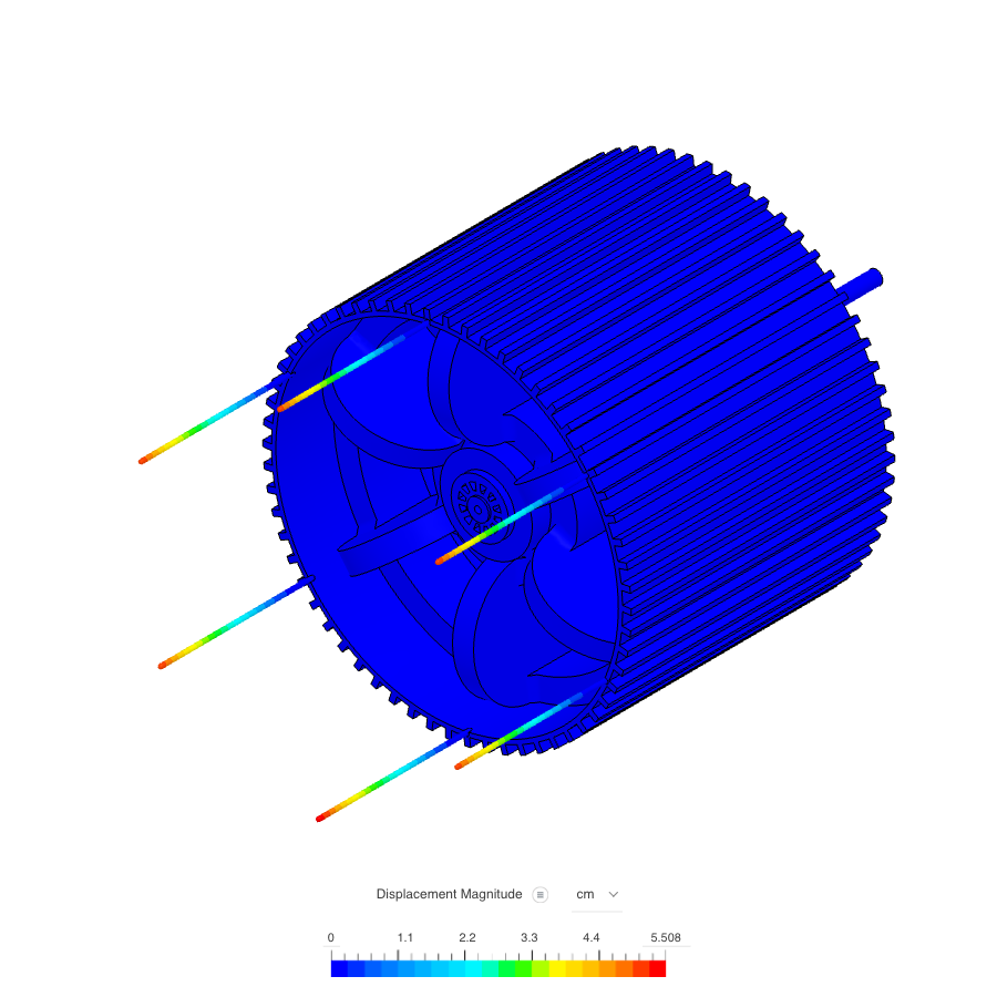
The FEA run simulates the displacement (in meters) of the spokes when the bladder is expanded. The spokes were designed to be made from Aluminum 6061-T6. Each spoke experiences a uniformly distributed load (UDL) of 150 Newtons acting radially outward from the center of the wheel. This simulates the internal pneumatic pressure created by the inflated bladder. The spokes only displaced a maximum of 5.508 cm, rounded up to 5.51 cm (or 5.51 x 10⁻² m), suggesting a high structural integrity under the intended maximum load (Figure 3).
AI-algorithm
An AI-powered terrain-recognition software automatically activates the pump to contract or expand the wheel. Simulation results suggest that this algorithm can effectively recognize the terrain and send the signal to the pneumatic pump for the wheel to expand before the rover enters the soft surface, in which it may sink (Figure 4). However, model optimization and validation using a larger image dataset are required to further prove its utility.
Mathematical Analysis
The first analysis included the calculation of the mean maximum pressure (MMP), which is an indicator of a vehicle’s tendency to sink into soft ground. MMP is important to assess the percent reduction in ground pressure due to the width expansion, which is then used to calculate the percent change in sinkage. This analysis included the following wheel parameters:
The initial width of the wheel,  , is 0.3251 meters (12.8”)
The diameter of the wheel,  , is 0.4064 meters (16”)
The length of the spokes,  , is 0.2014 meters (7.93”)
The expanded width, , is thus  , or 0.5265 meters (20.73”)
Hence:
This calculated increase in the area (61.95%) was slightly higher than that theoretically expected at the beginning of the study ( 50%). This mathematically calculated value, rounded to 62%, was used in the remaining part of the study, as presented further below.
Since  , a 62% increase in area decreases pressure by 38%
Bekker’s Equation: 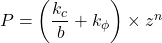 , where
  is sinkage.
For Mars dunes,  ,
,  ,
,  . When contracted,
  m. These values and formulas were based on the earlier study of ES-1 type of Martian soil by Brunskill31 When expanded, b = 0.527 m.
Therefore, expanding the width of the wheel is expected to decrease sinkage in Martian dunes by 35.2%.
The next analysis included the calculation of the theoretical maximum displacement, which is important for validating the FEA results against a concrete mathematical calculation.
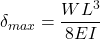
The theoretical maximum displacement ( ) of each spoke is given by the formula
  .
.
The FEA conditions were as follows:
 = 150 N
= 0.201 meters (7.93 inches)
 = 68.9 GPa (Young’s Modulus for aluminum 6061-T6)
 . For a 0.2-inch (0.00508 m) diameter rod,
is therefore 0.0660 meters, or 6.60 cm
The final analysis included the calculation of the safety factor, which is commonly used as an indication of reliability and structural capacity of the wheel:
The factor of safety (FoS) is given by 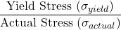
 of aluminum 6061-T6 is 276 MPa
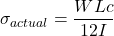 , where the values of , , and
  are given above, and
  = 0.00254 meters
Thus,  MPa
MPa
Therefore, 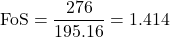 , which is the industry standard for aerospace engineering.
Discussion
This project designed a laterally-expanding wheel that expands its width to suit the terrain it is traveling upon. The wheel’s design includes a pneumatic pump to inflate an advanced balloon-like bladder that radially pushes out spokes to hold the bladder in place, thereby expanding the wheel’s width by half its diameter. A preliminary proof-of-concept AI-powered terrain-recognition algorithm was developed to automatically activate the pump to contract or expand the wheel. Simulation results and mathematical analysis suggested that this wheel can be used on future rovers sent to explore extraterrestrial bodies after more in-depth studies, which were out of the scope of the current study, are conducted.
This wheel design is expected to overcome the technical limitations of the vertically expandable wheels discussed in the introduction2,3,4. Additionally, another recent study described a wheel made of shape memory alloy2.While this design could potentially be used for the lateral wheel expansion, it has several limitations for space exploration. For example, it is made of soft materials, which would unlikely be able to support the massive payloads of larger rovers (like the 1-ton Curiosity) without significant distortion that hinders the stable movement of the rover. Additional stress of the origami wheel from sharp rocks or high-impact falls can cause permanent bending of the internal wire structures, which would lead to a total loss of function. Finally, constant folding and unfolding of this design, which is more complex than the A.T.L.A.S. wheel design, will likely result in the material’s fatigue. In a Martian environment, these creases are also susceptible to cracking, especially when combined with the 0.75 mm-thick aluminum skin designs that have previously shown premature wear20.
While experimental testing is required to evaluate the horizontally expanding wheel model presented in the current study, one may suggest potential limitations this model may have. The pneumatic balloon-like bladder may be punctured by sharp Martian rocks. Though the materials and three-layer design are intended to prevent the puncture-based failure, it would require experimental verification. If a slow leak occurs when the wheel is in the expanded mode, it may cause the wheel to sag, stall the drive motor, and force the AI algorithm into a continuous, battery-draining inflation loop. Mechanically, the spring-hatch spoke release mechanism may be susceptible to the harsh Martian environment, as fine, electrostatic dust can jam the hatches, freezing temperatures can embrittle the springs to cause fracturing, and intense UV radiation may result in a degradation of any exposed lubricants or non-metallic seals over time. Structurally, routing compressed gas through a hollow axle may reduce its torsional and bending strength, increasing the risk of structural failure under heavy payloads or high-impact terrain drops. Changing the wheel’s lateral width may also accelerate tire wear and significantly widen the turning radius when fully expanded. Therefore, experimental evaluation of these potential failure mechanisms is needed during the testing phase in a laboratory environment mimicking the conditions on Mars.
The FEA suggested a lower maximum displacement (5.51 cm) (Figure 3) than the perfect mathematical analysis (6.60 cm). This is expected because the FEA accounts for the slight flexibility of the wheel itself, whereas the formula assumes the wheel is infinitely stiff. This difference, therefore, suggests that the simulation is realistic and the spokes can handle a 150 N load without experiencing significant deformation.
While the Accuracy and Loss vs. Epoch analysis provided proof-of-concept and suggested that the system can be trained successfully to recognize various surfaces, this algorithm can be further optimized in the future using a more extensive image library. The weakness of the current analysis is that the algorithm was created using approximately 200 images. Increasing the number of images to millions would further help to optimize the algorithm and make it more suitable for the complex terrains, such as those experienced during space exploration.
Another limitation of this study was the assumption that the only stress mode acting on the spokes was the bending stress caused by the UDL of the balloon-like bladder when expanded. Other stress modes were considered but not modeled due to the technical limitations of the FEA software.
Additionally, the study assumes that the change in wheel surface area is directly proportional to the change in wheel contact area with the ground because the expanding width of the wheel is a linear function. As such, when the percent change is calculated using the total surface areas, the resulting percent change is also representative of the percent change in contact area. Future analysis is needed to refine these parameters and further validate this model.
Conclusions
An autonomous, reconfigurable wheel capable of lateral expansion to improve traction on soft and irregular terrains was designed and named A.T.L.A.S or Adaptive Tread Lateral Actuated System. The FEA analysis suggested that the simulation of the wheel expansion is realistic, and the spokes of the A.T.L.A.S. wheel can handle a 150 N load without experiencing plastic deformation.
The materials selected for the bladder are expected to ensure efficient pneumatic expansion because they are designed to provide structural integrity and maintain the functionality of the wheel under harsh conditions of space.
The AI algorithm for detecting terrain types can be scaled to accommodate more terrain types, as was suggested by the initial Accuracy and Loss vs. Epoch analysis presented in this study.
The mathematical analysis resulted in an aerospace-grade Safety Factor of 1.414, suggesting that this autonomous, laterally-expanding wheel is a feasible solution and warrants further studies.
Future Directions
Creating and testing a wheel prototype in a facility with equipment such as vacuum chambers, artificial gravity centers, and radiation testing facilities is the next step to experimentally verify the results of the current project.
Acknowledgements
Google Gemini 3.5 Flash model was used during the research phase to find published studies and identify publicly available images used in this project. I am grateful to my family for their support.
References
- NASA. Spirit. Accessed June 19, 2026, 2026. https://science.nasa.gov/mission/mer-spirit/ [↩]
- Lee, Kim, Kim, Park and Cho. Origami Wheel Transformer: A Variable-Diameter Wheel Drive Robot Using an Origami Structure. Vol. 4, pg. 163–180, Soft Robot, 2017, 10.1089/soro.2016.0038 [↩] [↩] [↩]
- Yoon, Kim, Park, Heo, Kim and Seo. 2 DOF transformable wheel design based on geared 8 bar parallel linkage mechanism. Vol. 14, pg. 379, Sci Rep, 2024, 10.1038/s41598-023-50804-y [↩] [↩]
- Zeng, Xu, Jiang and Gao. Development of a Novel Variable-Diameter Wheel. Vol. 9, pg. 4631, Applied Sciences, 2019 [↩] [↩]
- Gee-Clough. The effect of wheel width on the rolling resistance of rigid wheels in sand. Vol. 15, pg. 161–184, Journal of Terramechanics, 1978, https://doi.org/10.1016/0022-4898(78)90002-2 [↩]
- Meirion-Griffith and Spenko. Simulation and experimental validation of a modified terramechanics model for small-wheeled vehicles. Vol. 64, pg. 153–169, International Journal of Vehicle Design, 2014, 10.1504/ijvd.2014.058499 [↩]
- Bekker. Introduction to terrain-vehicle systems. Vol. pg. xvii, 846 p., 1969 [↩]
- Wong and Reece. Prediction of rigid wheel performance based on the analysis of soil-wheel stresses part I. Performance of driven rigid wheels. Vol. 4, pg. 81–98, Journal of Terramechanics, 1967 [↩]
- Tran. Modeling and Control of Unmanned Ground Vehicles. Vol. pg. PhD Thesis, , 2007 [↩]
- Tran, Kwok, Scheding and Ha. Dynamic Modeling of Wheel-Terrain Interaction of a UGV. Vol. pg. 3rd Annual IEEE Conference on Automation Science and Engineering,, 2007 [↩]
- Jia, Smith and Peng. Terramechanics-based wheel–terrain interaction model and its applications to off-road wheeled mobile robots. Vol. 30, pg. 491–503, Robotica, 2012, doi:10.1017/S0263574711000798 [↩] [↩]
- Azimi, Kövecses and Angeles. Wheel–Soil Interaction Model for Rover Simulation and Analysis Using Elastoplasticity Theory. Vol. 29, pg. 1271–1288, IEEE Transactions on Robotics, 2013, 10.1109/TRO.2013.2267972 [↩] [↩]
- Zhou, Chen, Tian, Tian, Huang and Wu. Calibration of Discrete Element Method Parameters for a High-Fidelity Lunar Regolith Simulant Considering the Effects of Realistic Particle Shape. Vol. 17, pg. Materials (Basel), 2024, 10.3390/ma17194789 [↩]
- Madden, Muruganandam, Missaoui, Gries, Kollmer, D’Angelo and Sinha-Ray. Behaviors of lunar regolith simulants under varying gravitational conditions. Vol. 11, pg. 69, NPJ Microgravity, 2025, 10.1038/s41526-025-00501-z [↩]
- Knuth, Johnson, Hopkins, Sullivan and Moore. Discrete element modeling of a Mars Exploration Rover wheel in granular material. Vol. 49, pg. 27–36, Journal of Terramechanics, 2012, https://doi.org/10.1016/j.jterra.2011.09.003 [↩]
- Park, Yoon, Kim, Kim and Seo. Review on Transformable Wheel: Mechanism Classification and Analysis According to Mechanical Complexity. Vol. 26, pg. 737–755, International Journal of Precision Engineering and Manufacturing, 2025, 10.1007/s12541-025-01224-7 [↩]
- NASA Mars Science Laboratory. Curiosity Rover Accessed June 19, 2026, 2026. https://science.nasa.gov/mission/msl-curiosity/ [↩]
- Rahimi Nohooji and Voos. Compliant Robotics in Space: A Prospective Review of Soft and Deformable Systems for Space Missions. Vol. 7, pg. 2400785, Advanced Intelligent Systems, 2025, https://doi.org/10.1002/aisy.202400785 [↩]
- Kuang, Gu, Rana, Zhao, Sun and Nnabuife. Semantic Terrain Segmentation in the Navigation Vision of Planetary Rovers—A Systematic Literature Review. Vol. 22, pg. 8393, Sensors, 2022 [↩]
- Rankin, Patel, Graser, Wang and Rink. Assessing Mars Curiosity Rover Wheel Damage. Vol. pg. 1–19, IEEE, 2022 [↩] [↩]
- Wang, An, Jiao, Lu, Qu, Xu, Sun and Li. Preparation and properties of fluorosilicone composites with thermal conductivity and chemical resistance through modification of filler and matrix. Vol. 225, pg. 110823, Polymer Degradation and Stability, 2024, https://doi.org/10.1016/j.polymdegradstab.2024.110823 [↩] [↩] [↩]
- Limeneh and Yilma. Article Review on Vectran-Super Fiber from Thermotropic Crystals of Rigid-Rod Polymer. Vol. 2021, pg. 6646148, Journal of Engineering, 2021, https://doi.org/10.1155/2021/6646148 [↩] [↩] [↩]
- Barros, Ribeiro and Santos. An Assessment of the Chemical Compatibility of Viton Fluoropolymers and Some Harsh Organic Liquid Mixtures. Vol. 11, pg. 2088, Processes, 2023 [↩] [↩] [↩]
- Barnett. Temperatures Across Our Solar System. Vol. 2026, pg. 2023 [↩]
- D.M. Hassler, Zeitlin C., Wimmer-Schweingruber R.F., et al. Mars’ Surface Radiation Environment Measured with the Mars Science Laboratory’s Curiosity Rover. Science. 343(6169):1244797.(2014) doi:doi:10.1126/science.1244797 [↩]
- FibrXL. Vectran. Accessed June 18, 2026, 2026. https://fibrxl.com/fibrxl-performance/fibers/vectran/ [↩] [↩] [↩]
- Gourdin and Jensen. Relaxation of compressive stress in gamma-irradiated Viton™ fluoroelastomer. Vol. 172, pg. 112714, Fusion Engineering and Design, 2021, https://doi.org/10.1016/j.fusengdes.2021.112714 [↩]
- Liu, Zhou and Feng. Effects of γ-ray radiation on the properties of fluorosilicone rubber. Vol. 78, pg. 110–112, Materials Letters, 2012, https://doi.org/10.1016/j.matlet.2012.03.065 [↩]
- ALFA Chemistry Fluoropolymers. Fluorosilicone. Accessed June 18, 2026, 2026. https://fluoropolymers.alfa-chemistry.com/products/fluorosilicone.html [↩] [↩]
- TysSeals. Viton(FKM) Seal Temperature Range. Accessed June 18, 2026, 2026. https://www.tysseals.com/blog/vitonfkm-seal-temperature-range/ [↩] [↩]
- Brunskill, Patel, Gouache, Scott, Saaj, Matthews and Cui. Characterisation of martian soil simulants for the ExoMars rover testbed. Vol. 48, pg. 419–438, Journal of Terramechanics, 2011, https://doi.org/10.1016/j.jterra.2011.10.001 [↩]