
Abstract
During the final touchdown phase, rockets face significant impact loads within brief durations (<100 milliseconds). The dampers integrated into the landing legs are used for absorbing energy and preventing excessive force transmission to the rocket’s main frame. This study explores the potential of magnetorheological (MR) dampers, which are able to dynamically adjust their damping coefficients to variable conditions, to improve landing safety and longevity. We hypothesized that an actively controlled MR damper would mitigate peak impact forces, vibrations, and rebound during landing compared to a passive damper due to its ability to adapt its damping coefficient to varying tested landing conditions such as velocity, vehicular attitude, and surface compliance. In order to test this hypothesis, we developed a computational simulation based on a one-degree-of-freedom mass-spring-damper model, utilizing fourth-order Runge-Kutta methods and a skyhook control algorithm. Two force metrics are distinguished: peak spring force (kx), the load at maximum landing leg compression, and peak total reaction force. The results showed that the MR damper reduced peak spring force across all nine scenarios tested by 32.7% to 42.0% and reduced maximum leg displacement. However, on peak total reaction force, the MR system was noticeably higher than the nominal passive damper in eight of nine scenarios, because its initial high compression-phase damping produces a large force spike at first contact. Running a sweep of fixed passive dampers across the MR coefficient range showed that a well-chosen fixed damper ( N
N s/m) minimizes peak total reaction force below that of the MR system. These results indicate that semi-active MR damping does not blanketly outperform passive damping. Overall, it selects a different point on a spring-force / total-force trade-off, offering promising advantages on some metrics while a well-tuned fixed damper remains competitive on others.
Keywords: Dampers, Magnetorheological, Rockets, Landing, Simulation
Introduction
Because of the growth in rocket launch services, there has been a greater focus on spacecraft reusability as a key way of lowering total costs. Reusable launch vehicles (RLVs) are able to recover their most costly components and fly them again by carrying out vertical propulsive landings1,2. The private company SpaceX, under the leadership of Elon Musk, was the first to make this progress. By using their Falcon 9 rocket, they have shown that a single booster can carry out dozens of flights, a situation which greatly reduces the manufacturing stress experienced by the spacecraft over its service life3. Yet the huge structural loads placed on the spacecraft’s structure when it lands are still the most demanding throughout the whole flight4.
In the last phase of touchdown, the vehicle shifts from free-fall deceleration to rigid-body contact with the ground within milliseconds, even though the use of retrorockets cannot be ruled out. This results in impulsive compressive forces which are passed through the landing legs and into the main airframe5,6. The loads can increase considerably because of variations in touchdown velocity, the vehicle’s attitude at the time of contact, and the compliance of the landing surface7. Furthermore, as the number of launches continues to rise and the number of flights for which vehicles are reused reaches into the dozens, fatigue builds up as a result of the repeated high-amplitude landings8.
Traditional landing systems make heavy use of passive damping systems, such as aluminum honeycomb crush cores or fixed-coefficient shock absorbers9,10. They dissipate kinetic energy by means of structural deformation or viscous flow at a damping coefficient which was determined at the time of design and optimized for normal operating conditions11. There is a considerable risk when the actual conditions at touchdown differ from this design point, whether because of variations in velocity or attitude.
Semi-active control systems provide a solution to this dilemma by allowing the damping force to be adjusted in real time, without having to use the power or mechanical complexity associated with fully active damping technologies12. Magnetorheological (MR) dampers are an example of semi-active dampers and have been widely studied in areas such as automotive suspension, civil seismic isolation, and prosthetics research13,14,15,16. A magnetic rheological damper consists of micron-scale ferromagnetic particles which are suspended in a carrier oil17. When there is no electromagnetic field present, the fluid acts as a normal viscous fluid, but when the external electromagnetic coil inside the damper is energized, the particles arrange themselves into a chain-like structure that opposes flow, thereby increasing the viscosity and so the damping force in proportion to the current applied18,19. This change is reversible and always takes place within 10 to 20 milliseconds20.
The damping coefficient can therefore be changed continuously from a minimum passive level to a maximum field-on state by adjusting the current in the coil according to real-time data from the sensor inputs21. Various control strategies for MR dampers have been investigated in different fields22. The skyhook algorithm, which was first developed for use with vehicle suspension, is widely employed in the control of semi-active dampers23.
Compared with passive dampers, MR dampers have been looked at in both automotive and civil engineering situations, but their relative performance when it comes to rocket landing legs has been given little consideration, and previous comparisons have seldom separated the two different loads that a damper transmits, namely, the spring force at peak compression and the total reaction force at first contact. Since these two loads are minimized by different damping levels, a comparison that is based on only one of them might mislead as to which damper provides better protection for the structure. The present study removes this deficiency by assessing both of these measures under a common range of landing conditions and by investigating whether a simple two-state (skyhook) MR controller actually performs better than a fixed passive damper or is merely choosing one point on a trade-off that a fixed damper is also capable of reaching.
We suggested that a semi-actively controlled MR damper would lead to a reduction in the peak structural forces, the settlement time, and the maximum leg displacement when compared with passive dampers in nine different landing situations.
We hypothesized that a semi-actively controlled MR damper would reduce peak structural forces, settlement time, and maximum leg displacement compared to passive dampers across nine different landing conditions.
Methods
Physical model
The rocket landing was simulated by means of a one-degree-of-freedom mass-spring-damper system, the system modeling the behavior of a single landing leg under axial compressive load24. The model was defined by three parameters: a mass m of 5,000 kg, this being the vehicle load distributed to one leg; a leg spring stiffness k of 150,000 N/m; and a damping coefficient c which varied according to the damper configuration. These parameter values were selected to apply to a booster-class vehicle and were not intended to refer to a specific launch system. Since the first stage of the Falcon 9 rocket has a dry mass of 25,000 kg distributed over four landing legs, 5,000 kg per leg is a reasonable order of magnitude for the load that a single leg carries at touchdown. The leg spring stiffness of 150,000 N/m was chosen so that the undamped natural frequency would be approximately 5.3 rad/s, which gives a compression stroke of the order of tens of centimeters at the nominal touchdown velocity, a figure that is in line with the stroke range of deployable landing gear. As the objective of this study is to compare the different damper configurations under the same conditions rather than to predict the absolute loads for a particular vehicle, the conclusions are based on the relative behavior of the two dampers and not on the exact values of the parameters; a sensitivity study confirming this is provided in the Results. The equation of motion used was
(1) 
In this case,  refers to leg displacement,
  to leg velocity, and
  to leg acceleration. The value of leg displacement is taken as being measured from the position at which the leg first makes contact with the ground when no load is applied, so that, under the influence of gravity, the vehicle comes to a static equilibrium at a position given by
  ; this static equilibrium position defines the meaningful state in which the vehicle has landed, and a contact clamp ensures that the leg does not experience any tension after separation. The total reaction force transmitted to the vehicle structure at any given time step was calculated using the formula
  . Two force metrics were provided: the peak spring force (
 ), which is determined at the point of maximum leg compression and thus represents the load that the frame has to carry when the leg is at its deepest point; and the peak total reaction force (
 ), which represents the entire load transmitted through the leg, the damper component being the dominant one at the first moment of contact. It is necessary to report both of these metrics because the two are minimized by different damping levels.
Damper configurations
Two different damper setups were modeled and compared using the predefined simulation conditions. The passive damper coefficient was calculated from the critical damping coefficient  Ns/m. A passive coefficient of
  Ns/m was chosen as a typical example of an underdamped value for a landing leg, this corresponding to a damping ratio of
  . This value was selected as a realistic fixed-tuning option for a passive shock absorber and thus acts as the baseline configuration; it remained constant in all scenarios no matter the landing conditions, since passive systems have a fixed-tuning feature. In order to determine whether the MR damper’s advantage comes from the active control of the damping coefficient or merely from the ability to achieve higher damping, a series of fixed passive coefficients covering the full range of the MR damper was also carried out.
The MR damper was set to have a minimum damping coefficient of  Ns/m and a maximum coefficient of
  Ns/m, this giving a critical damping ratio of
  , which is at the near-critical threshold. In accordance with the skyhook control law that was implemented, the active coefficient was switched (approximately 3,000 times) between these two values at each timestep to control the MR damper.
Numerical integration
Since the control law reallocates the MR damper coefficient c at each time step, the equation of motion cannot be solved analytically and numerical integration had to be used. A fourth-order Runge-Kutta (RK4) method was implemented in Python with the aid of the NumPy library in order to advance the system state in time25. At each time step, four slope estimates of the state derivatives were calculated and combined into a weighted average to update both displacement and velocity with fourth-order accuracy. A fixed time step of  ms was applied throughout and each simulation was carried out for 3,000 time steps, which corresponds to 3 seconds of landing dynamics, a period long enough to include the complete impact, peak compression, rebound, and settlement phases under all the tested conditions. The integrator was checked against the closed-form analytical solutions (see Model validation).
Skyhook control algorithm
The MR damper was controlled using an industry-standard skyhook control algorithm, the algorithm being required to make a single binary decision about damping at each time step according to the measured leg velocity . If the leg velocity was in the downward direction while the leg was being compressed, the damping coefficient  was set at Ns/m, this giving a damping ratio near critical so as to oppose the incoming velocity and to limit the maximum displacement of the leg. When the leg velocity changed direction during the rebound stroke, the coefficient was reduced to
  Ns/m in order to avoid the damper applying a compressive force to the structure as it extended. The passive damper kept its fixed coefficient of 15,000 Ns/m during both phases.
Test matrix
The nine landing situations were obtained by altering one independent variable at a time while holding the other two at their nominal values, with one scenario involving combined stress and another representing an extreme case in order to look at how the vehicle performs under complex off-nominal conditions (as indicated in Table 1). The landing velocity was tested at 1.5, 3.0, 6.0, and 8.0 m/s. The vehicle’s attitude was studied at 0°, 5°, 10°, and 15° tilt, tilt being indicated by a reduction in effective vertical velocity as given by the equation v₀ = v·cos(θ). Since tilt is only taken into account through this decrease in velocity, its effect on the peak force is only small by design; a full examination of the lateral and multi-leg effects is beyond the scope of the 1-DOF model (see Limitations). Surface compliance was represented by a ground stiffness parameter which was set at 2,000,000 N/m for hard surfaces, 800,000 N/m for medium surfaces, and 200,000 N/m for soft surfaces. The nominal condition employed in all the variable tests was 3.0 m/s, 0° tilt, and medium surface compliance, this being the condition for which the passive damper coefficient was adjusted. Each scenario was simulated twice, once for each damper configuration, with all the other initial conditions remaining unchanged.
| Scenario | Landing velocity (m/s) | Attitude (°) | Surface | Ground stiffness (N/m) | Group |
| S1 | 1.5 | 0 | Medium | 800,000 | Velocity sweep |
| S2 | 3.0 | 0 | Medium | 800,000 | Velocity sweep (nominal) |
| S3 | 6.0 | 0 | Medium | 800,000 | Velocity sweep |
| S4 | 3.0 | 0 | Hard | 2,000,000 | Surface sweep |
| S5 | 3.0 | 0 | Soft | 200,000 | Surface sweep |
| S6 | 3.0 | 5 | Medium | 800,000 | Attitude sweep |
| S7 | 3.0 | 10 | Medium | 800,000 | Attitude sweep |
| S8 | 6.0 | 10 | Hard | 2,000,000 | Combined off-nominal |
| S9 | 8.0 | 15 | Hard | 2,000,000 | Combined off-nominal (extreme) |
Passive coefficient sweep
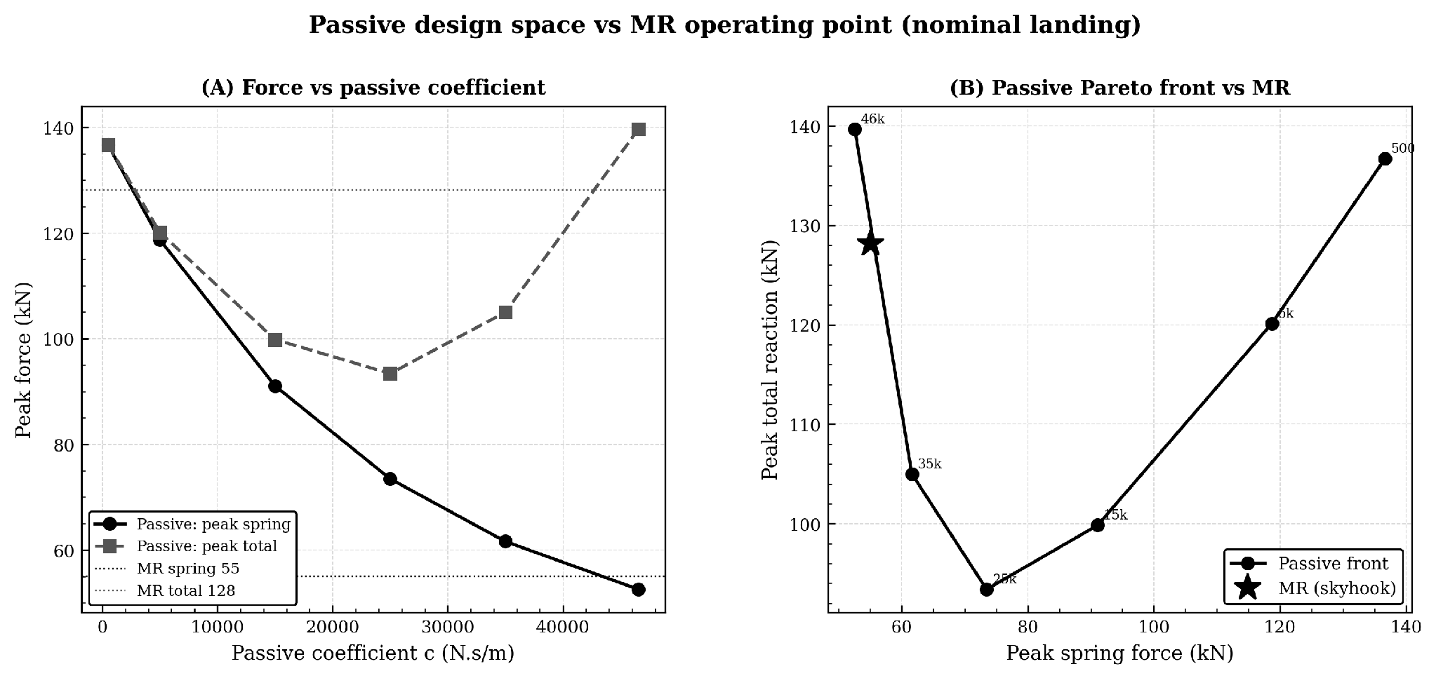
To characterize the passive design space, a fixed passive damper was simulated at coefficients of 500, 5,000, 15,000, 25,000, 35,000, and 46,556 N·s/m under nominal conditions, and both peak spring force and peak total reaction force were recorded for each. This sweep establishes the best performance achievable by any single fixed damper on each metric, against which the semi-active MR system can be fairly compared.
Parameter sensitivity
To ensure that the comparison between damper types did solely depend on a specific choice of vehicle parameters, the nominal scenario was repeated with varied masses between 3,000 to 8,000 kg at fixed stiffness and with leg stiffness varied from 75,000 to 300,000 N/m at fixed mass.
Model validation
The simulation’s integrator and model were validated against known solutions. For the undamped free vibration, the RK4 result matched the closed-form solution  to within
  m over 2 s, and total mechanical energy was conserved to within
  . For damped free vibration, the result matched the analytical underdamped solution to within m. Under gravity, the simulated static equilibrium matched the analytical value
  cm exactly. A timestep-convergence check (
 , and
, and  ms) showed peak-force values averaged near 0.1%, confirming convergence at the 1 ms timestep. An independent solver reproduced the nominal passive peak spring force to within 0.001 kN.
Output metrics
Five outputs were recorded per scenario per damper type. Metrics: peak spring force (kN), defined as  at maximum leg compression, and peak total reaction force (kN), defined as the maximum of , served as the primary structural metrics. Force reduction percentage was computed as
  for each metric separately. Settlement time (s) was found from start to the time until leg velocity fell below 0.01 m/s and leg displacement reached the static equilibrium within 0.001 m. Maximum leg displacement (cm) was recorded as the peak compression reached during the impact stroke.
Results
Overview of simulation results
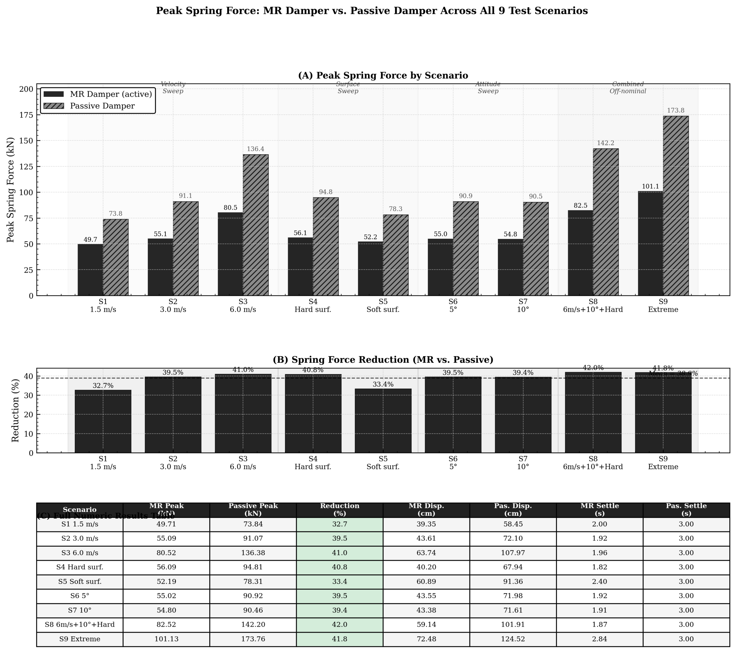
The simulation was run across all the defined landing scenarios in the test matrix, with each scenario run twice under identical initial conditions between the MR and passive damper configurations to establish the comparison. Across the scenarios, the MR damper reduced peak spring force and maximum leg displacement relative to the nominal passive damper (Table 2). The peak spring force reductions were between 32.7% and 42.0%, with a final average of 38.9% (Figure 1). However, on peak total reaction force, the full load transmitted through the leg, the MR system was higher than the nominal passive damper in eight of the nine scenarios, ranging from 19.9% to 76.2%, the sole exception being the gentlest landing (S1, 1.5 m/s). This occurs because the MR damper applies near-critical damping at the instant of contact, when leg velocity is greatest, producing a large damper-force spike (cẋ) that the spring-force metric alone does not capture.
The MR system settled to equilibrium in 1.92 s at nominal conditions, whereas the nominal passive damper did not settle within the 3 s simulation window. The earlier reported settlement figures corresponded to a model without gravitational preload and are superseded by these values (see Discussion).
| Scenario | MR spring (kN) | Pas. spring (kN) | Spring red. (%) | MR total (kN) | Pas. total (kN) | Total red. (%) | MR disp (cm) | Pas. disp (cm) |
| S1 (1.5 m/s) | 49.7 | 73.8 | 32.7 | 66.6 | 79.0 | +15.7 | 39.4 | 58.5 |
| S2 (3.0 m/s, nom) | 55.1 | 91.1 | 39.5 | 128.2 | 99.8 | −28.4 | 43.6 | 72.1 |
| S3 (6.0 m/s) | 80.5 | 136.4 | 41.0 | 256.3 | 154.6 | −65.8 | 63.7 | 108.0 |
| S4 (hard) | 56.1 | 94.8 | 40.8 | 134.7 | 103.3 | −30.4 | 40.2 | 67.9 |
| S5 (soft) | 52.2 | 78.3 | 33.4 | 105.6 | 88.1 | −19.9 | 60.9 | 91.4 |
| S6 (5°) | 55.0 | 90.9 | 39.5 | 127.7 | 99.7 | −28.1 | 43.6 | 72.0 |
| S7 (10°) | 54.8 | 90.5 | 39.4 | 126.2 | 99.1 | −27.4 | 43.4 | 71.6 |
| S8 (6m/s+10°+hard) | 82.5 | 142.2 | 42.0 | 265.3 | 159.5 | −66.3 | 59.1 | 101.9 |
| S9 (extreme) | 101.1 | 173.8 | 41.8 | 347.0 | 196.9 | −76.2 | 72.5 | 124.5 |
Effect of touchdown velocity
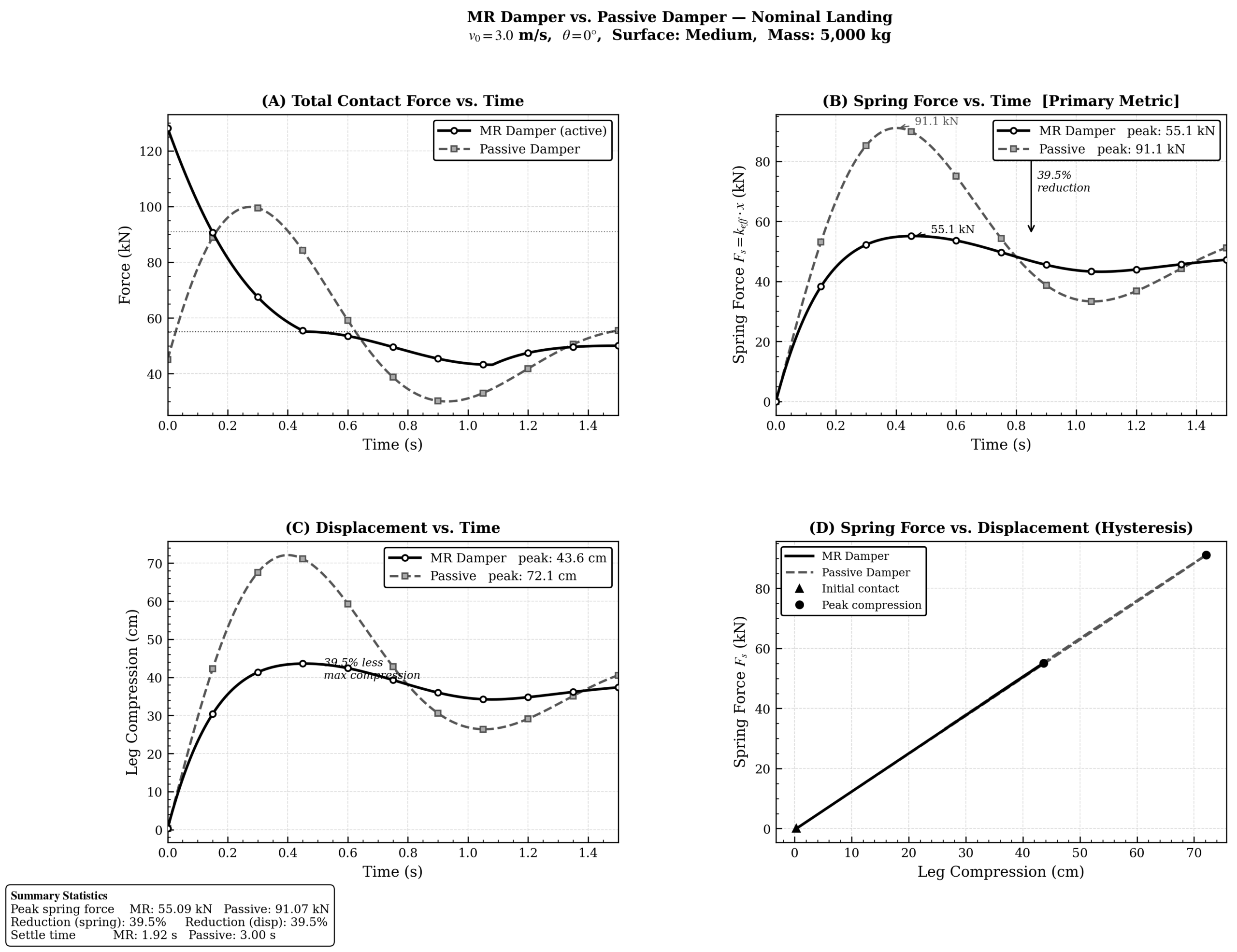
The scenarios S1, S2, and S3 were designed to determine the effect of landing velocity by keeping the vehicle attitude at 0° and the surface type at medium compliance. When the landing velocity was 1.5 m/s (S1), the passive damper resulted in a peak spring force of 73.8 kN whereas the MR damper produced 49.7 kN, which represents a 32.7% reduction. At the nominal velocity of 3.0 m/s (S2), the peak spring force was 91.1 kN with passive damping and 55.1 kN with MR damping, a reduction of 39.5%. The nominal scenario also showed a maximum leg displacement of 72.1 cm with passive damping and 43.6 cm with MR damping. In the case of 6.0 m/s (S3), the passive system generated 136.4 kN and the MR system 80.5 kN, a 41.0% reduction. However, regarding the peak total reaction force the order was reversed at higher speeds: at 3.0 m/s the MR total was 128.2 kN as compared to 99.8 kN for the passive system, and at 6.0 m/s it was 256.3 kN compared to 154.6 kN, indicating that the contact-spike penalty increases as the touchdown velocity rises.
Effect of vehicle attitude
Scenarios S6 and S7 involved tilt angles of 5° and 10°, respectively, at a speed of 3.0 m/s on a medium surface. The effect of tilt was shown by a decrease in the effective vertical velocity, this being represented by the equation  , so that the 5° case resulted in a velocity of 2.99 m/s and the 10° case in 2.95 m/s. The maximum spring forces in both cases were almost the same as in the nominal case (S2): 55.0 kN (MR) compared with 90.9 kN (passive) at 5°, and 54.8 kN as against 90.5 kN at 10°, in each instance a reduction of nearly 39.5%. Since in the 1-DOF model tilt is the only influence and that comes about through the small
  reduction in velocity, the change in peak force caused by varying the attitude is negligible; however, because of the way this study is structured, a proper evaluation of the effect of attitude would need more advanced modeling capabilities as discussed in the Limitations.
Effect of surface compliance
Scenarios S4 and S5 involved ground stiffnesses of 2,000,000 N/m and 200,000 N/m, respectively, at a speed of 3.0 m/s and a tilt angle of 0°. On the hard surface (S4) the passive damper generated 94.8 kN and the MR damper 56.1 kN, which represented a 40.8% reduction in spring force. On the soft surface (S5) the passive damper produced 78.3 kN and the MR damper 52.2 kN, corresponding to a 33.4% reduction. Like in the other cases, the soft surface resulted in lower absolute peak forces for both systems when compared to the medium surface, as can be expected since the lower effective stiffness distributed the impact impulse over a longer period. As in the other scenarios too, the MR system’s advantage in terms of spring force was accompanied by a higher peak total reaction force than that of the passive system on the hard surface.
Combined and extreme scenarios
Scenario S8 included a speed of 6.0 m/s, a tilt of 10°, and a hard surface, which resulted in a passive peak spring force of 142.2 kN and an MR peak spring force of 82.5 kN (a reduction of 42.0%). Scenario S9, the most severe combination (8.0 m/s, 15° tilt, and a hard surface), gave a passive peak spring force of 173.8 kN and an MR peak spring force of 101.1 kN (a reduction of 41.8%). In each case, however, the MR system’s peak total reaction force was considerably higher than that of the passive damper: 159.5 kN compared with 265.3 kN in the case of S8, and 196.9 kN compared with 347.0 kN in the case of S9, the greatest total-force penalties in the entire matrix, caused by the high contact velocities.
Passive coefficient sweep
Examining the MR damper’s coefficient range with a fixed passive damper (as shown in Figure 3) showed the underlying reasons for these results. When the fixed coefficient was increased from 500 to 46,556 N·s/m, the peak spring force decreased steadily from 136.7 kN to 52.5 kN. The peak total reaction force, on the other hand, followed a U-shaped pattern: it was high at low coefficients (due to large compression), dropped to a minimum of 93.4 kN when c was about 25,000 N·s/m, and then increased once again at high coefficients (because of the contact spike). The MR system was found at the point (spring 55.1 kN, total 128.2 kN). Thus, a fixed passive damper with a coefficient of approximately 46,556 N·s/m matched the MR system in terms of spring force (52.5 kN), while a fixed passive damper with a coefficient of about 25,000 N·s/m achieved a lower total reaction force (93.4 kN) than the MR system. To put it simply, the MR operating point is within the passive design envelope rather than outside it: none of the metrics on which the MR system outperforms can be achieved by a fixed damper that is properly selected.
Parameter sensitivity
Whatever the mass of the modeled mass was, when it was varied from 3,000 kg to 8,000 kg, the magnitude of the two peak forces changed but the direction of the results remained the same: in every case the MR damper decreased the peak spring force, the amount of reduction being 34.3% at 3,000 kg and rising to 42.2% at 8,000 kg, while it also produced a higher peak total reaction force than the passive damper, the amount by which it exceeded the passive damper being 49.0% at 3,000 kg and falling to 7.2% at 8,000 kg. In the same way, when the leg stiffness was changed from 75,000 to 300,000 N/m, the same pattern was obtained, with the spring-force reductions increasing from 29.1% to 45.7% and the total-force penalties rising from 14.5% to 38.6%. The advantage of the MR system with regard to spring force and its total-force penalty is therefore not affected by the choice of vehicle parameters within the ranges tested, although the size of these advantages and penalties does vary. Notably, the total-force penalty decreases as the modeled mass increases and increases as leg stiffness increases, this being in agreement with the contact-spike mechanism described above.
Discussion
Restatement of key findings
The simulation indicated that the MR damper decreased the peak spring force and the maximum leg displacement as compared with the nominal passive damper in all nine cases (with a mean reduction in spring force of 38.9%), but it did not result in a reduction of the peak total reaction force: in eight out of the nine scenarios the MR system transmitted a greater total load than the nominal passive damper, and the passive coefficient sweep demonstrated that a properly selected fixed damper can match or exceed the MR system in terms of either criterion alone. The main conclusion is therefore not that the MR damping performs better than passive damping overall, but rather that the two types of damping lie at different points on a trade-off between spring force and total force. The MR controller reduces the peak spring force by damping strongly during compression, even though this causes a larger spike in the contact force; a fixed passive damper can be adjusted to reduce either the spring force peak or the total force peak, but not both at the same time.
Connection to objectives
The hypothesis was only partly confirmed. Although the MR damper did reduce both the peak spring force and the maximum leg displacement, in line with the hypothesis, it did not manage to lower the total reaction force transmitted to the structure and performed worse than an appropriately tuned fixed passive damper with regard to that specific criterion. The key characteristic of the MR system is its adaptability. When compression is occurring the skyhook algorithm sets c to c_max = 46,556 N·s/m and during rebound c is set at c_min = 500 N·s/m. Applying near-critical damping during compression causes the leg velocity to be rapidly brought to a stop and reduces leg travel, thus decreasing the peak spring force (since F = k_eff·x is proportional to compression). Yet the high level of damping during the compression phase also results in a large cẋ term at the first point of contact, which is the reason why the total reaction force is higher for the MR system than for a moderately damped fixed passive damper. The near-zero damping during rebound does prevent the damper from adding compressive force when the leg is extending, and this remains a real advantage of the semi-active system over a fixed damper that has the same compression-phase coefficient.
Implications and significance
What this means is that the type of damper that turns out to be better depends on the performance criterion selected. If the limiting factor is the peak spring force (in other words, the deep-stroke structural load), then the MR system gives a real advantage over a passively damped system which is only moderately tuned. But when the limiting factor is the peak total reaction force (that is, the full load at the point where the leg is attached, including the contact spike), which is often the case in carrying out structural size calculations, a fixed passive damper tuned near c ≈ 25,000 N·s/m is either as good as or better than the two-state MR controller looked at in this study. Each landing cycle results in a certain amount of fatigue damage to the vehicle’s main structure, the amount of damage being directly proportional to the peak load experienced. Since the two types of damper behave differently depending on the two load measures, a design decision based on fatigue considerations requires that one first establish which of the loads is governing the critical structural feature before selecting a damper. The findings also show that a more advanced control law, for example, one that varies the damping continuously rather than switching between two states, or one that limits the coefficient during the contact phase, could in principle provide the benefits associated with the spring force without suffering the penalty from the total force; this therefore represents a potential area for future research rather than a feature of the current controller.
As for settlement time: in the first version of the manuscript it was stated that there was an 8% reduction in settlement time (the time going from 0.65 s to 0.60 s). These figures were obtained with a model that did not include the effect of gravitational preload and in which the system relaxed to x = 0. In the revised model, which does take gravity into account, settlement is determined by the system’s approach to static equilibrium and is therefore considerably slower; under normal conditions the MR system required 1.92 s to settle while the nominal passive damper did not settle within 3 s. Settlement time is therefore not an appropriate criterion on which to base firm conclusions from this model, and the earlier figure of 8% is thus withdrawn.
Comparison with published results
The extent of the spring-force reduction reported in this study is generally in line with the results of previously published comparisons between skyhook-controlled MR dampers and passive dampers in other areas. Experimental tests using a quarter-car setup have shown that an on-off skyhook MR damper reduces sprung-mass acceleration by about 15% as compared with an equivalent passive damper, the figure increasing to around 24% when a fuzzy-Lyapunov controller is used26. In the case of semi-active MR seat suspensions under skyhook control, acceleration reductions have been reported to range from about 11% to 52% depending on the excitation frequency27, and a recent hybrid-mode MR damper achieved vertical acceleration reductions of 30% to 40% in vehicle tests28. Thus, the spring-force reduction in the present study, which lies between 32.7% and 42.0%, is within the range of values previously reported for skyhook-type semi-active control.
The following point is a methodological one. The studies mentioned above give figures for acceleration or for vibration amplitude, quantities which are determined by the same deep-stroke dynamics as the peak spring force, rather than by the total instantaneous load transmitted through the mount at the first point of contact. Our current results show that a semi-active controller can improve the first of these while worsening the second, which means that comparisons based on a single metric may underestimate the trade-off involved. This does not contradict the previously published results, but it does show that the selection of the metric used for reporting has a significant effect on the apparent advantage of semi-active control.
Limitations
The generalizability of these findings is limited by several features of the simulation. To begin with, the model is based on a one-degree-of-freedom, single-leg approach and therefore does not simulate the independent behavior of multiple landing legs nor their mechanical interaction. In reality, RLVs land on four to six legs at the same time, and when there is a tilt, one or more legs make contact with the surface before the others, leading to asymmetric load distributions a single-leg model is unable to reproduce. Since tilt is represented merely by reducing the effective vertical velocity, the attitude cases (S6, S7) must be interpreted as an approximation in terms of velocity rather than as a true simulation of a tilted landing; the aspect of asymmetric multi-leg contact is not included within this model.
Secondly, real MR fluid takes between 10 and 20 milliseconds to respond when there is a change in the applied current, while the simulation assumes that the coefficient switches instantaneously at each 1 ms time step. This means that the speed of the MR response is overestimated. Specifically, the big spike in contact force which penalizes the MR system in terms of total reaction force would be somewhat lessened by a realistic actuation lag; however, the qualitative conclusion that the MR system does not exceed a well-tuned fixed damper in terms of total force is not overturned by this effect, since the spike would have to be completely eliminated in order for the ranking to change.
Third, although the model based on spring surface compliance takes into account the effect of ground stiffness on the magnitude of the peak force, it does not account for surface deformation or for the energy absorption that occurs within the ground itself; in practice soft surfaces such as soil absorb part of the impact energy directly and thus reduce the leg loads further than the simple spring approximation would predict.
In the end, a linear viscous damping term was used to model the MR damper instead of a nonlinear constitutive model such as the Bingham plastic or Bouc-Wen formulation29. A nonlinear model would have been able to more accurately represent the field-dependent yield stress behavior of real MR fluid and could have altered the magnitude of the contact-force spike which causes the total-force result.
Recommendations
Future research should focus on extending the model to include a multi-leg coupled simulation in order to account for asymmetric loading caused by tilting and cross-wind conditions. The next area of priority is the control law itself. Since the two-state skyhook controller involves a contact-force penalty, it should be examined whether a continuously modulated controller, either one that limits the contact-phase coefficient or one that explicitly minimizes the total reaction force rather than the spring force, can retain the advantages of the spring force without incurring the associated total-force cost. Simulating the real MR fluid activation time by introducing a response lag of 10 to 20 timesteps would enable more conservative and realistic estimates of performance. In the longer term, validation against actual hardware (this could be achieved by conducting benchtop drop tests on an instrumented MR leg assembly or by comparing the results with published flight telemetry from previous RLV landing missions) would show how well the simulation predictions translate into real landing conditions.
Closing thought
The study assumed that a semi-active MR damper would perform better than a passive damper in simulated rocket landings; instead, it arrived at a more interesting conclusion: although the MR system has the potential to considerably reduce both the spring force and displacement parts of the landing load, it also increases the total force. A well-tuned passive damper remains competitive in all the criteria looked at and turns out to be better than the MR damper when it comes to the total force transmitted. Rather than finding a general performance advantage, several nuances need to be taken into account. If a net benefit is to be achieved through that flexibility, control laws that aim directly at the total transmitted load and models that take into account the multi-leg, nonlinear, and actuation-lag effects left out in this study will be required. The fact that this study identifies the trade-off is a necessary first step before active-controlled damping systems can eventually become more widespread.
Appendix
https://github.com/madhav-dotcom/mrDamperCode
References
- NASA. Reusable launch vehicle technology program. NASA Technical Reports Server. 1996. [↩]
- Wertz JR, Larson WJ. Space mission analysis and design. Microcosm Press. 1999. [↩]
- SpaceX. Falcon 9 user’s guide. 2021. [↩]
- Sutton GP, Biblarz O. Rocket propulsion elements. John Wiley & Sons. 2010. [↩]
- NASA. Landing dynamics research. 2015. [↩]
- NASA. Spacecraft impact dynamics research. 2010. [↩]
- Fortescue P, Swinerd G, Stark J. Spacecraft systems engineering. John Wiley & Sons. 2011. [↩]
- Thomson WT, Dahleh MD. Theory of vibration with applications. Prentice Hall. 1997. [↩]
- NASA. Evaluation of a full-scale lunar module landing gear. NASA Technical Note TN D-4474. NASA Technical Reports Server. 1968. [↩]
- Rakheja S, Sankar S. Vibration and shock isolation performance of a semi-active “on-off” damper. Journal of Sound and Vibration. 1988. [↩]
- Gavin HP. Multi-duct ER dampers. Journal of Intelligent Material Systems and Structures. 2001. [↩]
- Karnopp D. Design principles for vibration control systems using semi-active dampers. Journal of Dynamic Systems, Measurement, and Control. 1990. [↩]
- Dyke SJ, Spencer BF, Sain MK, Carlson JD. Modeling and control of magnetorheological dampers for seismic response reduction. Smart Materials and Structures. 1996. [↩]
- Wereley NM, Pang L. Nondimensional analysis of semi-active electrorheological and magnetorheological dampers using approximate parallel plate models. Journal of Intelligent Material Systems and Structures. 1998. [↩]
- Stanway R, Sproston JL, Stevens NG. Non-linear modelling of an electro-rheological vibration damper. Journal of Electrostatics. 1987. [↩]
- Carlson JD, Spencer BF. Magnetorheological fluid dampers: Scalability and design issues for application to dynamic hazard mitigation. Proceedings of the 5th International Conference on Motion and Vibration Control. 1998. [↩]
- Jolly MR, Bender JW, Carlson JD. Properties and applications of commercial magnetorheological fluids. Journal of Intelligent Material Systems and Structures. 1999. [↩]
- Choi SB, Lee SK, Park YP. A hysteresis model for the field-dependent damping force of a magnetorheological damper. Journal of Sound and Vibration. 2001. [↩]
- Zhu X, Jing X, Cheng L. Magnetorheological fluid dampers: A review on structure design and analysis. Journal of Intelligent Material Systems and Structures. 2012. [↩]
- Carlson JD. What makes a good MR fluid? Journal of Intelligent Material Systems and Structures. 2002. [↩]
- Wang J, Meng G. Magnetorheological fluid devices: Principles, characteristics, and applications in mechanical engineering. Mechatronics. 2001. [↩]
- Du H, Sze KY, Lam J. Semi-active H∞ control of vehicle suspension with magnetorheological dampers. Journal of Sound and Vibration. 2005. [↩]
- Karnopp D, Crosby MJ, Harwood RA. Vibration control using semi-active force generators. Journal of Engineering for Industry. 1974. [↩]
- Meirovitch L. Fundamentals of vibrations. McGraw-Hill. 2001. [↩]
- Hairer E, Nørsett SP, Wanner G. Solving ordinary differential equations I: Nonstiff problems. Springer. 1993. [↩]
- Experimental quarter-car comparison of on-off skyhook and fuzzy-Lyapunov skyhook controlled MR dampers against an OEM passive damper. Journal of Central South University. 2012. [↩]
- Semi-active seat suspension with magnetorheological damper under skyhook control. Frontiers in Materials. 2020. [↩]
- Hybrid damping mode MR damper: development and experimental validation with semi-active control. Machines. 2025. [↩]
- Spencer BF, Dyke SJ, Sain MK, Carlson JD. Phenomenological model for magnetorheological dampers. Journal of Engineering Mechanics. 1997. [↩]